
STR-VX250 - Empfänger SONY - Kostenlose Bedienungsanleitung
Finden Sie kostenlos die Bedienungsanleitung des Geräts STR-VX250 SONY als PDF.


Benutzerfragen zu STR-VX250 SONY
0 Frage zu diesem Gerät. Beantworten Sie die, die Sie kennen, oder stellen Sie Ihre eigene.
Eine neue Frage zu diesem Gerät stellen
Laden Sie die Anleitung für Ihr Empfänger kostenlos im PDF-Format! Finden Sie Ihr Handbuch STR-VX250 - SONY und nehmen Sie Ihr elektronisches Gerät wieder in die Hand. Auf dieser Seite sind alle Dokumente veröffentlicht, die für die Verwendung Ihres Geräts notwendig sind. STR-VX250 von der Marke SONY.
BEDIENUNGSANLEITUNG STR-VX250 SONY
SONY®
FM STEREO/FM-AM RECEIVER
STR-VX250
OPERATING INSTRUCTIONS
Before operating the unit, please read this manual thoroughly. This manual should be retained for future reference.
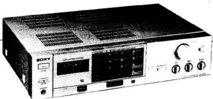
natural_image
Front view of a Sony audio amplifier console (no visible text or labels beyond branding)OWNER'S RECORD
The model and serial numbers are located at the rear. Record the serial number in the space provided below. Refer to these numbers whenever you call upon your Sony dealer regarding this product.
Model No. STR-VX250
Serial No.
WARNING
To prevent fire or shock hazard, do not expose the unit to rain or moisture.
text_image
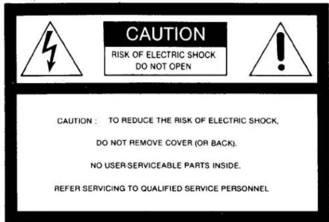
CAUTION RISK OF ELECTRIC SHOCK DO NOT OPEN CAUTION : TO REDUCE THE RISK OF ELECTRIC SHOCK, DO NOT REMOVE COVER (OR BACK). NO USER-SERVICEABLE PARTS INSIDE. REFER SERVICING TO QUALIFIED SERVICE PERSONNEL
The lightning flash with arrowhead symbol, within an equilateral triangle, is intended to alert the user to the presence of uninsulated "dangerous voltage" within the product's enclosure that may be of sufficient magnitude to constitute a risk of electric shock to persons.

The exclamation point within an equilateral triangle is intended to alert the user to the presence of important operating and maintenance (servicing) instructions in the literature accompanying the appliance.
FEATURES
The STR-VX250 with its Direct Access System, makes station selection easier than ever. The STR-VX250 also employs the quartz-locked digital synthesizer system in a separate state-of-the-art tuner section and provides medium-high power output for your home audio system from its amplifier section.
●Phono amplifier stage, which employs an IC, is carefully designed to improve stereo separation and signal-to-noise ratio.
●The quartz-locked digital synthesizer system with a sophisticated Phase Locked Loop (PLL) circuit allows extremely precise tuning of FM and AM stations with an electronic digital readout on the frequency display.
A new IC recently developed by Sony allows a high comparison frequency thus eliminating the tendency for a low comparison frequency, which had been previously generally employed, to slip into the audio range and degrade the signal-to-noise ratio.
●Four methods of tuning are available:
Direct access tuning: FM or AM stations can be directly tuned in by inputting the station frequency with the DIRECT TUNING buttons.
Automatic tuning: the FM band is scanned automatically until a signal is received.
Manual tuning: AM tuning can be accomplished either by changing the frequency display reading step by step or slowly to monitor the frequency.
Memory preset tuning: a desired pre-memorized station can be instantly received by pressing the PRESET TUNING button.
●The pre-memorized stations are retained in memory by two back-up batteries when the power is turned off. These back-up batteries also allow the last station tuned in to be held in memory.
TABLE OF CONTENTS
Precautions 3
System connections 4
Connection notes 4
Connection diagram 4
Speaker connection 5
FM antenna connection 6
AM antenna connection 6
Program source connections 6
Ground connection 6
AC outlets 6
Location and function of controls 7
Battery installation 9
Preparation 9
Broadcast reception 10
Direct access tuning 10
Automatic tuning (for FM reception) 10
Manual tuning (for AM reception) 11
Memory preset tuning 11
Station label insertion 12
Other operating instructions 12
Reproduction of phono, CD/AUX and tape program
sources 12
Tape recording 12
FM antennas....13
Trouble checks 14
Specifications 15
PRECAUTIONS
On safety
● Operate the unit only on 120 V ac, 60 Hz.
● Should any liquid or solid object fall into the cabinet, unplug the unit and have it checked by qualified personnel before operating it any further.
● Unplug the unit from the wall outlet if it is not to be used for an extended period of time. To disconnect the cord, pull it out by grasping the plug. Never pull it out by the cord.
On installation
- Do not install the unit in a location near heat sources such as radiators or air ducts, or in a place subject to direct sunlight, excessive dust, mechanical vibration or shock.
● Good air circulation is essential to prevent internal heat build-up in the unit. Place the unit in a location with adequate air circulation. Do not place the unit on a soft surface, such as a rug that would block the ventilation holes on the bottom. - Do not place anything on top of the cabinet. The top ventilation holes must be unobstructed for the proper operation of the unit and to prolong the life of its components.
- Do allow more than 15 cm (6 inches) of space behind the unit so that the position of the built-in ferrite-bar antenna can be adjusted.
On operation
● Before making program source connections, be sure to turn the power switch off and unplug the unit.
● Do not attempt to test the protection circuits by blocking the ventilation holes or connecting improper loads.
- When the unit is not used, turn the power off, to conserve energy and to extend the useful life of your unit.
On cleaning
Clean the cabinet, front and rear panels periodically with a soft dry cloth. If the stains are difficult to remove, use a cloth moistened with a mild detergent solution. Do not use solvents such as alcohol, benzine or thinner, since they will damage the finish.
On repacking
Do not throw away the carton and the packing material. It makes an ideal container to transport the unit in. When shipping the unit for repair work or to another location, repack it as illustrated on the carton box.
For the customers in the USA
For detailed safety precautions, see the leaflet "IMPORTANT SAFEGUARDS".
Note about the AM channel plan selector
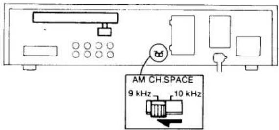
This receiver has a two-position AM channel plan selector on the rear. To tune in AM stations correctly, the selector should be correctly set according to the AM frequency allocation system of your country.
10 kHz: for countries where the frequencies are allocated at intervals of 10 kHz, for example, the USA and Canada.
9 kHz: for countries where the frequencies are allocated at intervals of 9 kHz.
This selector is factory preset at 10 kHz. If the AM frequencies are allocated at intervals of 9 kHz in your country, the selector should be set to 9 kHz. Be sure to turn off the power before changing the position of the selector.
text_image
AM CH.SPACE 9 kHz 10 kHzNotes
- If the selector is set incorrectly, you cannot tune in AM stations properly.
- When the selector is changed, the preset frequencies and the last station memory will be erased. In this case, memorize the frequencies again.
SYSTEM CONNECTIONS
CONNECTION NOTES
●The power cord should be connected last of all, first making sure that the POWER switch is turned off.
●To assure correct matching at the input and output terminals of your audio system, refer to the "SPECIFICATIONS" on page 15, and to the specifications given in the instruction manuals provided with the components you wish to connect to the receiver. Generally the output level of a signal source (phono cartridge, tape recorder, etc.) should be equal to or slightly greater than the sensitivity of the corresponding input. Also the output impedance of a signal source should be considerably lower than the impedance of the corresponding input.
- For all program source input and output connections, use a low-capacitance type shielded cable. Keep the cables as short as practicable. Excessively long runs tend to reduce the high frequency response. Also, keep the cables away from the power cord or speaker cords to avoid hum pickup.
- When connecting program sources or tape recorders, note that the red jacks of the receiver are for right-channel connections and the white jacks for left-channel connections.

text_image
STR-VX250 L R white plug red plug Program source L R●The cable connectors should be fully inserted into the jacks. A loose connection may cause hum and noise.
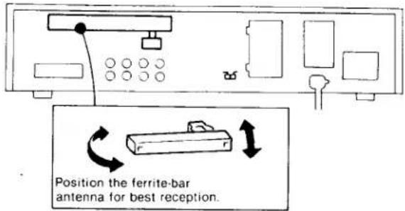
- Since there is a variety of cords—such as speaker cords, power cord, connecting cords—around the rear panel terminals, you should maintain a moderate separation between the bar antenna and the cords. This is because the receiver may produce a noise from the direct touch of the cords on the bar antenna.
CONNECTION DIAGRAM
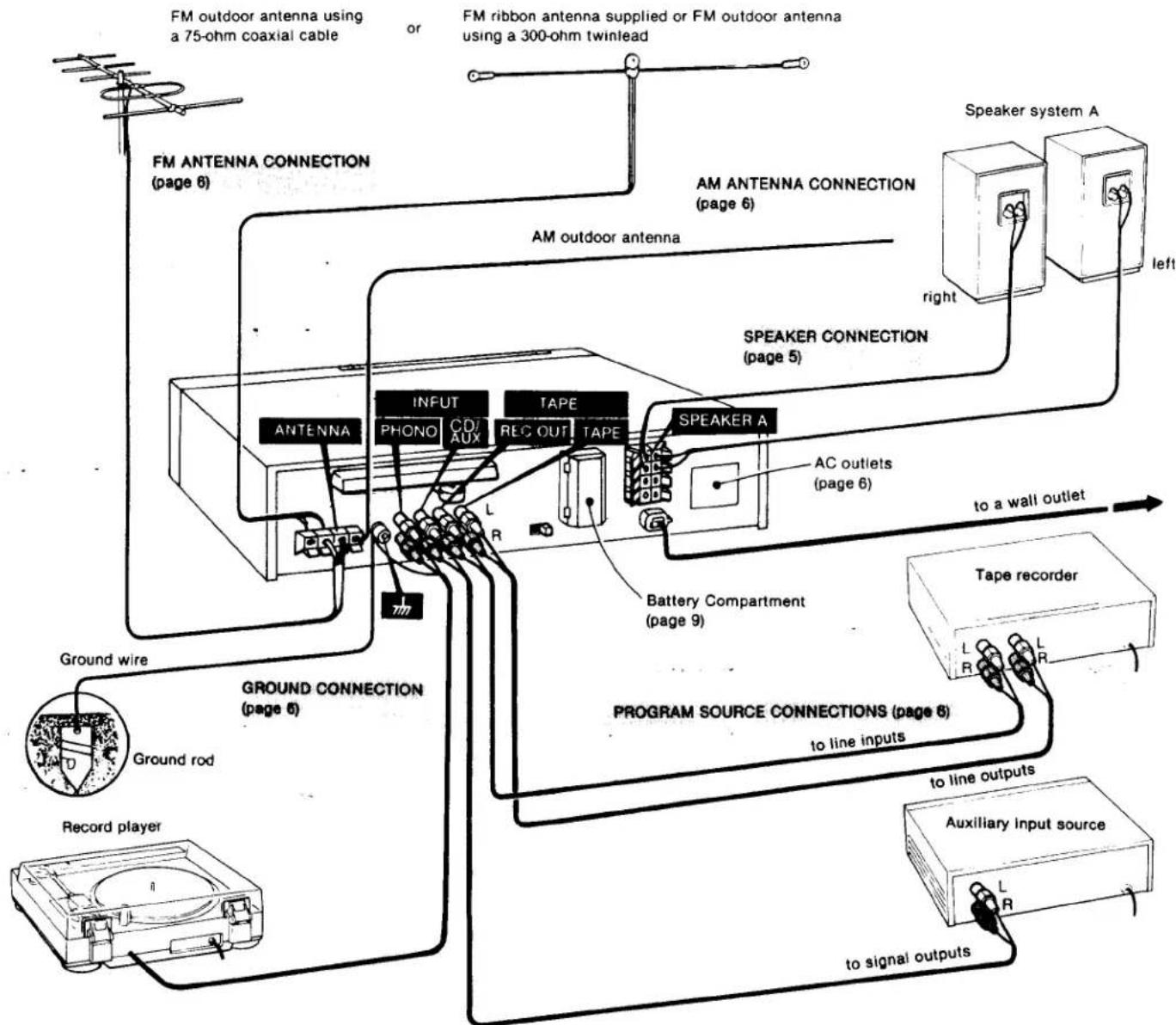
flowchart
graph TD
    A["FM outdoor antenna using a 75-ohm coaxial cable"] --> B["FM antenna connection (page 6)"]
    C["FM ribbon antenna supplied or FM outdoor antenna using a 300-ohm twinlead"] --> D["AM antenna connection (page 6)"]
    D --> E["Speaker system A"]
    E --> F["arrow"]
    G["Ground wire"] --> H["Ground rod"]
    H --> I["Record player"]
    I --> J["Ground connection (page 6)"]
    J --> K["Ground wire"]
    L["Ground wire"] --> M["Tape recorder"]
    N["Ground wire"] --> O["Auxiliary input source"]
    P["Ground wire"] --> Q["to signal outputs"]
    R["Ground wire"] --> S["to line outputs"]
    T["Ground wire"] --> U["to line inputs"]
    V["Ground wire"] --> W["Battery Compartment (page 9)"]
    X["Ground wire"] --> Y["PROGRAM SOURCE CONNECTIONS (page 6)"]
    Z["Ground wire"] --> AA["to line outputs"]
    AB["Ground wire"] --> AC["to signal outputs"]
    AD["Antenna"] --> AE["INPUT"]
    AD --> AF["TAPE"]
    AD --> AG["SPEAKER A"]
    AH["PHONO"] --> AI["L"]
    AJ["C/D AUX"] --> AK["L"]
    AL["REC OUT TAPE"] --> AM["L"]
    AN["SPEAKER CONNECTION (page 5)"] --> AO["AC outlets (page 6)"]
    AP["Speaker system A"] --> AQ["right"]
    AR["Speaker system A"] --> AS["left"]
SPEAKER CONNECTION
This receiver has provision for two pairs of speaker systems—system A and system B—which can be selected individually or simultaneously by means of the front panel SPEAKERS switches.
Note that the speaker systems A and B are series-connected.
No sound will be heard if only one of the speaker systems is connected and the SPEAKERS switches A and B are depressed.
Speaker power capacity
This receiver is rated at 20 watts minimum RMS per channel with an 8-ohm load from 20 - 20,000 Hz and may deliver an instantaneous peak power much greater than the rated power. Be sure to use speakers with adequate power handling capabilities. Always reduce the volume, when setting down or removing a tonearm or when tuning across the band. Speaker damage may result if these precautions are not observed.
Speaker cable type
Common 18-gauge lamp cord (the center conductor of 1 mm in diameter) is fine for short runs. However, 16-gauge (1.3 mm) to 14-gauge (1.6 mm) may be needed for long runs to prevent excessive power losses in the wiring.
Connecting speaker cord to the receiver
Connect each speaker to the corresponding receiver speaker terminals, i.e. right speaker to the [R] speaker terminals and left speaker to the [L] speaker terminals.
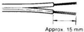
① Strip approx. 15 mm ( ^5/_8 ) of outer covering from the speaker cord.
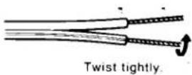
② Twist the wire ends for easy insertion.
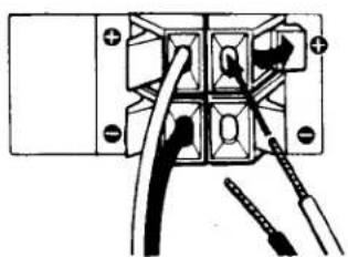
● Depress the terminal button as illustrated and fully insert the twisted wires into the slot. Then release the button.
Note that the colored or marked lead of a speaker cord goes to the terminal and the remaining one to the terminal, to avoid making any incorrect connections.
natural_image
Pure electrical circuit lines without any symbols① After these procedures are completed, pull on the speaker cord lightly to see if the connection is secure.
Speaker phasing
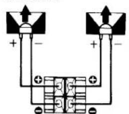
Correct ⊕ ∘ connection of both paired speakers insures proper in-phase operation. If the speaker system is out-of-phase, the bass tones seem to be missing and the position of the instruments becomes obscure.
Proper phasing
text_image
Electrical circuit diagram showing two voltage sources connected to a grid of components with polarity labelsBoth speaker cones move in the same direction.
Improper phasing
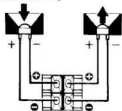
text_image
Electrical circuit diagram with labeled terminals and polarity indicatorsThe ⊕ ⊖ connections of right speaker are reversed, so the two cones move in opposite directions.
Speaker placement
Here are a few suggestions for speaker placement that will assist you in obtaining an installation with satisfactory stereo sound.
Normally, the speakers are placed on the floor against the narrower wall of a room. The bass sounds can then be increased by moving the speakers toward the corners, or decreased by raising the speakers off the floor on suitable pedestals, and/or moving them away from the wall a moderate distance. If the speakers are positioned above the floor, do not place them higher than ear-level while seated, since this produces an unnatural effect.
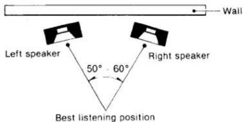
The distance between speakers, or the speakers and a listener depends mainly on the room size. Generally it is recommended that the speaker/listener relationship be an equilateral triangle configuration (as illustrated).
If the speaker separation is too wide, an undesirable "hole in the middle" effect occurs.
text_image
Wall Left speaker 50° - 60° Right speaker Best listening positionPlace the right and left speakers in similar acoustic environments, otherwise you will obtain unbalanced sound. For example, placing one speaker near an open door or archway will decrease the apparent bass from that speaker.
Best sound is usually obtained in a room with carpeting on the floor, heavy draperies and upholstered furniture. Since each room has its own individual acoustic characteristic, which is a function of its size, construction and furnishing, some experimentation with speaker placement is generally necessary before the correct balance of stereo image and bass response is obtained. This will be time well spent, resulting in your enjoyment of the maximum capabilities of your music system.
FM ANTENNA CONNECTION
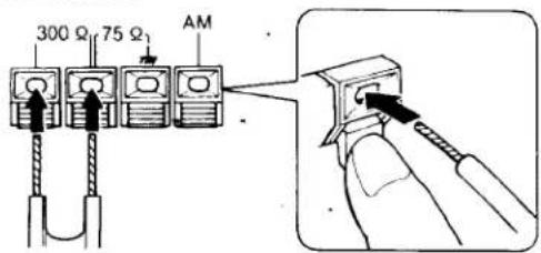
The receiver accepts either 300-ohm twinlead or 75-ohm coaxial cable. Standard 300-ohm twinlead is inexpensive but susceptible to the pickup of extraneous noise. 75-ohm coaxial cable is free from external interference, reduces noise pickup, and is the ideal transmission line for most FM installations.
75-ohm coaxial cable connection
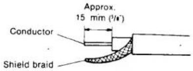
① Cut and remove the outer and inner covering as shown and twist the shield braid and the conductor.
text_image
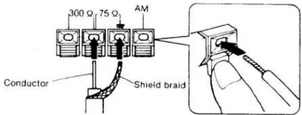
Approx. 15 mm (1/6") Conductor Shield braid② Connect the conductor and shield braid as illustrated.
text_image
300 Ω 75 Ω₁ AM Conductor Shield braid③ Pull the cable lightly to make sure the connection is secure.
300-ohm twinlead connection
text_image
300 Ω 75 Ω AMTo route the twinlead over the roof or outerwall, use stand-off insulators. Keep the lead as short as possible and avoid running parallel to other wires or metal pipes.
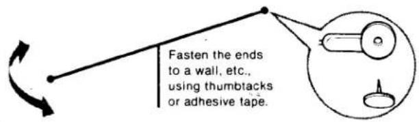
Ribbon antenna supplied
Until you install a suitable outdoor antenna, the supplied ribbon antenna may be useful. Connect it to the 300-ohm antenna terminals. For optimum reception, fully extend the antenna and position it for the best reception.
text_image
Fasten the ends to a wall, etc., using thumbtacks or adhesive tape.AM ANTENNA CONNECTION
In most areas, the built-in ferrite-bar antenna will provide satisfactory reception. In difficult reception areas, it may be necessary to connect a length of insulated wire 5-15 meters (20-50 feet) long to the AM ANTENNA terminal. Extend this out of doors if possible, keeping the greater portion horizontal.
text_image
Position the ferrite-bar antenna for best reception.PROGRAM SOURCE CONNECTIONS
Record player
The PHONO inputs accept a typical moving-magnet (MM) cartridge.
Tape recorder
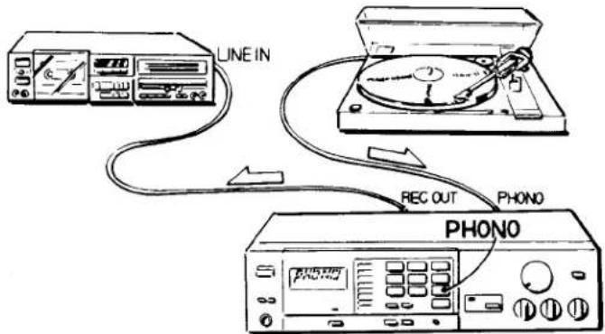
The tape recorder jacks are provided to connect a tape deck: TAPE for playing back a tape, and REC OUT for recording.
Other input sources
The CD/AUX inputs are provided for connecting various input sources such as a tape recorder (for playback only), an additional tuner, or a record player equipped with a ceramic cartridge. (The CD/AUX and TAPE inputs are identical in sensitivity and input impedance.)
GROUND CONNECTION
When an outdoor antenna is installed, the direct connection of the ground terminal [π] to a good ground is recommended for lightning protection. The use of a lightning arrester is recommended for any outdoor antenna.
To prevent hum, be sure to connect the ground wire of the record player to the ground terminal. If hum still exists, it may be helpful to connect the ground terminal directly to earth via a ground rod or other good ground, such as a clamp on a cold water pipe.
AC OUTLETS
Receptacles on the rear panel provide a convenient source of ac power for other system components.
The SWITCHED outlet is controlled by the front panel POWER switch and can supply ac power up to 100 watts.
The UNSWITCHED outlet is not controlled by the POWER switch and can supply ac power up to 100 watts.
Note: Never run electrical home appliances such as an electric iron, fan or TV from these outlets.
LOCATION AND FUNCTION OF CONTROLS
Before plugging in or attempting to operate this receiver.
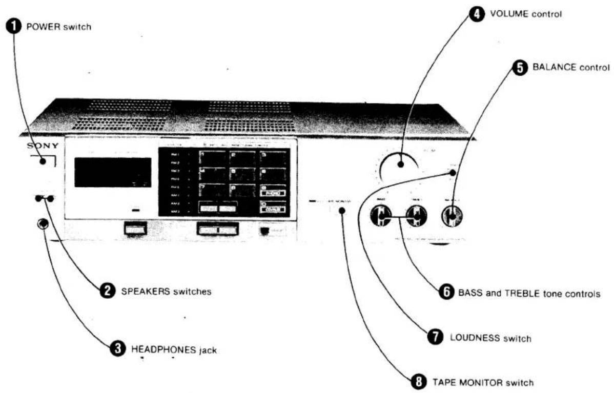
it is suggested that you familiarize yourself with all its switches and the purpose of each. Each number in the photo is keyed to the descriptive text.
Amplifier section
text_image
POWER switch VOLUME control BALANCE control 2 SPEAKERS switches 3 HEADPHONES jack 6 BASS and TREBLE tone controls 7 LOUDNESS switch 8 TAPE MONITOR switchPOWER switch
Depress-to turn on the power. To turn the power off, press the switch again.
② SPEAKERS switches
To drive speaker system A, depress the A switch.
To drive speaker system B, depress the B switch.
To drive both speaker systems A and B, depress both A and B switches.
③ HEADPHONES jack
Accepts any low or high impedance stereo headphones.
For headphone monitoring only, keep the SPEAKERS switches OFF.
VOLUME control
Regulates the overall sound level.
Clockwise rotation of the VOLUME control increases the sound level and counterclockwise rotation decreases it.
Be sure to lower the volume whenever you turn the receiver on or off, or make system connections.
⑤ BALANCE control
Governs the amount of sound coming from each paired speaker to get optimum stereo effect. When you turn the BALANCE control to the right, the left channel volume is decreased, and vice versa.
⑥ BASS and TREBLE tone controls
These knobs control the prominence of bass and treble response. Clockwise rotation increases response; counterclockwise rotation decreases it. Normally keep these at the "0" position.
Adjust the tone to the acoustic condition of the listening room or to your preference.
⑦ LOUDNESS switch
Normally keep the switch released (☐ OFF). When listening to program sources at a low VOLUME control setting, depress the switch (☐ ON).
This loudness control compensates for the human ear's decreased response to very low frequency sound at low volume levels, and provides an apparently uniform response. The effect of this control gradually decreases as the volume is increased by the VOLUME control.
⑧ TAPE MONITOR switch
To listen to a taped program, depress the switch. The indication above the switch will light up, indicating that a playback output from the tape recorder connected to the TAPE jacks can be heard.
Tuner section
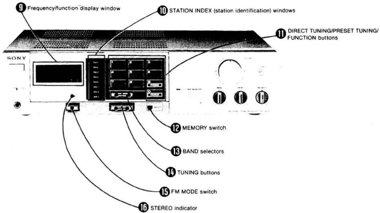
text_image
9 Frequency/function display window 10 STATION INDEX (station identification) windows 11 DIRECT TUNING/PRESET TUNING/FUNCTION buttons 12 MEMORY switch 13 BAND selectors 14 TUNING buttons 15 FM MODE switch 16 STEREO indicator⑨ Frequency/function display window
During broadcast reception
During reproduction of record source or auxiliary input source
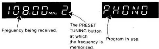
text_image
108.00 MHz 2 Frequency being received. The PRESET TUNING button at which the frequency is memorized. PHONO Program in use.⑩ STATION INDEX (station identification) windows
Station labels (supplied) identifying pre-memorized stations can be placed in these windows.
Press the button according to the following desired purposes. The pressed figures will be displayed on the frequency/function display window.
To tune in the frequency directly, press the BAND selector and the buttons.
To call up a pre-memorized station, press the appropriate button. Reproduction of record and auxiliary sources (the 9 and 0 buttons serve as FUNCTION buttons)
Press to select between PHONO (9) or CD/AUX (0).
Press to operate memory circuit. The "0" indicator will appear on the frequency/function display window for a few seconds indicating that the memory circuit is standing by.
Press the appropriate selector to select the desired band: FM or AM.
Press either the "+" or "-" button to change the frequency: Press the "-" button to go to a lower frequency and the "+" button to go to a higher.
Press to start the automatic frequency scanning (in 0.05 MHz steps).
Press and keep the button depressed to change the frequency continuously, in 10 kHz steps (or 9 kHz steps). To change the frequency rapidly, press and release the button immediately.
During FM reception, when a stereo signal of sufficient strength is received, the receiver operates in the stereo mode. (The STEREO indicator will illuminate.)
When you want to tune in a very weak FM station, or when an FM program is too noisy, press this switch. (The STEREO indicator illumination will go out.) Press it again to return to the stereo mode. The mode will automatically return to the stereo mode when the frequency is changed.
This indicator will light when an FM stereo program of sufficient signal strength is tuned in.
⑪ DIRECT TUNING/PRESET TUNING/FUNCTION buttons
Direct access tuning (the 1 to 0 buttons serve as DIRECT TUNING buttons)
Memory tuning (the 1 to 8 buttons serve as PRESET TUNING buttons)
⑫ MEMORY switch
⑬ Band selectors
TUNING buttons
During FM reception :
During AM reception :
⑮ FM MODE switch
16 STEREO indicator
BATTERY INSTALLATION
To retain the frequencies memorized on the PRESET TUNING buttons while the receiver is turned off, install two batteries in the battery compartment at the rear as follows.
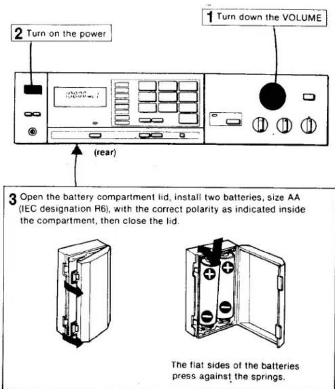
text_image
2 Turn on the power 1 Turn down the VOLUME (rear) 3 Open the battery compartment lid, install two batteries, size AA (IEC designation R6), with the correct polarity as indicated inside the compartment, then close the lid. The flat sides of the batteries press against the springs.Battery life
About one year of operation can be expected when using Sony SUM-3(NS) New Super Batteries (or Eveready Heavy Duty Batteries No. 1215). Be sure to replace the batteries once a year to avoid damage from leaking batteries.
Note
Be sure to turn on the receiver before installing or replacing the batteries.
If the batteries are installed or replaced with the power turned off, incorrect figures will appear in the frequency/function display.
In that case :
Leave the unit with power off for 30 minutes.
② Turn on the power.
③ Install the two batteries.
Place the desired frequencies in memory again.
PREPARATION
Before proceeding to any type of operation, set the controls and switches as shown.
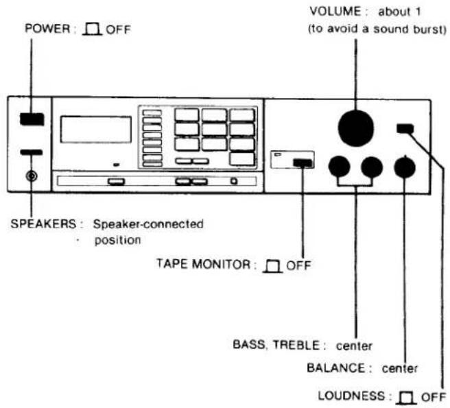
text_image
POWER : OFF SPEAKERS : Speaker-connected position TAPE MONITOR : OFF VOLUME : about 1 (to avoid a sound burst) BASS, TREBLE : center BALANCE : center LOUDNESS : OFFBROADCAST RECEPTION
This receiver incorporates the following tuning systems which give the listener a choice of four ways in which to tune in the desired broadcast.
Direct access tuning
If you know the frequency of the station to be received, you can tune in the station easily by this system.
Auto tuning (for FM reception) Manual tuning (for AM reception)
These systems are convenient for receiving a station whose frequency has not been memorized, or to see what kind of programs are on the air.
Memory preset tuning
Once you program the frequencies into the memory, all you need do to tune in a station is to press the appropriate button.
DIRECT ACCESS TUNING
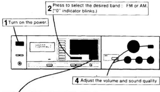
Follow the numbered sequence.
text_image
1 Turn on the power. 2 Press to select the desired band: FM or AM. ("0" indicator blinks.) 4 Adjust the volume and sound quality3 Pressing the DIRECT TUNING button, input the frequency of the station to be received.
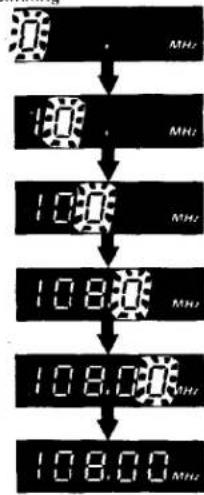
Example 1: FM 108.00 MHz
blinking
flowchart
graph TD
    A["Input"] --> B["10 MHz"]
    B --> C["10 MHz"]
    C --> D["108 MHz"]
    D --> E["108 MHz"]
    E --> F["108.00 MHz"]
    F --> G["108.00 MHz"]

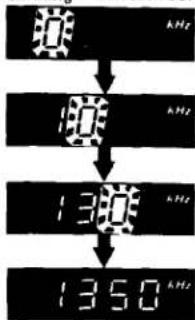
Example 2: AM 1350 kHz
(with AM channel plan blinking selector set to 10 kHz)
text_image
1300 1350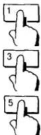
The "0" will appear automatically.
You can now hear the station whose frequency you have just input.
Notes on the AM direct access tuning
- If the AM channel plan selector is set to 10 kHz, the last digit "0" of the frequency will be automatically set when the first two or three digits are input.
- If the AM channel plan selector is set to 9 kHz, input the frequency to the last digit.
When the wrong frequency is input
- If you mistakenly press a wrong figure, press the appropriate BAND selector again and input the correct frequency.
- If you input a frequency outside the receiver's frequency range (FM: 87.5 to 108 MHz, AM 530 to 1,610 kHz), the figures will flash on and off in the frequency/function display. In this case, press the appropriate BAND selector and input the proper frequency.
AUTOMATIC TUNING (for FM reception)
Follow the numbered sequence.
1 Turn on the power.
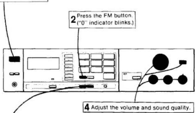
text_image
2 Press the FM button. ("0" indicator blinks.) 4 Adjust the volume and sound quality.3 Press the "+" or "-" TUNING button to start automatic frequency scanning. There is no need to hold the button down.
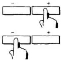
for higher frequencies
for lower frequencies
The frequency figures will change rapidly and stop when a signal is received. If the received signal is not the desired one, press the button again.
To stop the automatic tuning, press the MEMORY switch.
If the signal strength is weak, the frequency display figures will not stop at the desired frequency. When this happens, adjust the antenna for optimum reception. If the signal strength is still too weak for automatic tuning, tune in the station as described in "DIRECT ACCESS TUNING".
When the frequency figures reach the end of the tuning range of each band, the frequency will then be scanned from the opposite end of the tuning range.
MANUAL TUNING (for AM reception)
Follow the numbered sequence.
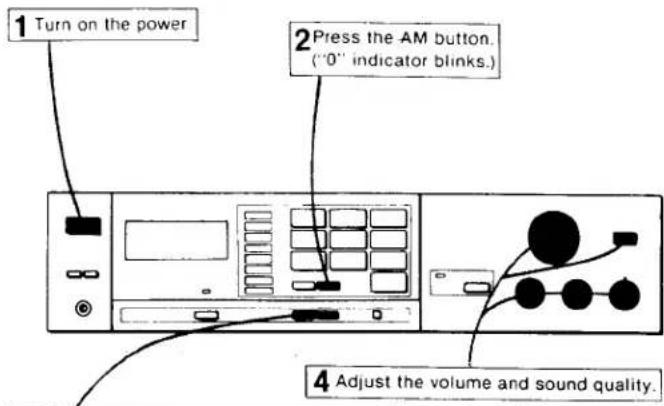
text_image
1 Turn on the power 2 Press the AM button. ("0" indicator blinks.) 4 Adjust the volume and sound quality.3 Press the "+" or "-" TUNING button.
The frequency will change in 10 kHz (or 9 kHz) steps.
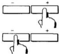
for higher frequencies
for lower frequencies
Keep either of the TUNING buttons depressed or repeatedly press and immediately release the button until the correct frequency is indicated.
To quickly tune in a roughly known frequency
You can quickly tune in an FM or AM station whose frequency is roughly known by combining the TUNING button operation with direct access tuning. Input the approximate frequency with the direct access tuning, then press either the "+" or "-" button. For example, if you believe your station is between 700 and 800 kHz, input 7 and press the "+" button, or input 8 and press the "-" button.
MEMORY PRESET TUNING
A total of eight FM or AM stations or a combination of both can be preset in any sequence.
To memorize station frequencies
To memorize a station, first tune in the station then, follow the numbered sequence.
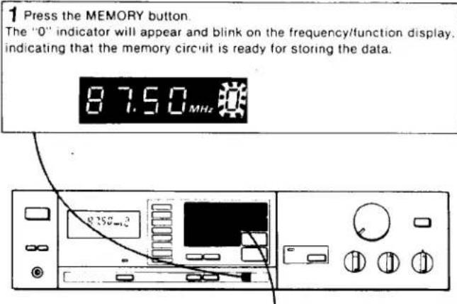
text_image
1 Press the MEMORY button. The "0" indicator will appear and blink on the frequency/function display. indicating that the memory circuit is ready for storing the data. 87.50MHz 258-3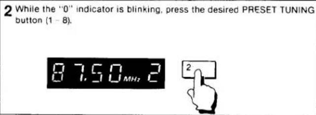
text_image
2 While the "0" indicator is blinking, press the desired PRESET TUNING button (1 - 8). 87.50 MHz 2 2Repeat these steps for each PRESET TUNING button.
Replace the station labels to conform to the selected pre- memorized stations. See "STATION LABEL INSERTION" on page 12.
Notes
● The "0" indicator will go off automatically after a few seconds. When the indicator is out, the memory circuit does not operate to memorize the station.
● The previous memory will be erased when a new frequency is programmed in the memory of the same button. An erasure cannot be made without a new input.
To receive a pre-memorized station
Turn the POWER switch on and simply press the desired PRESET TUNING button.
Memory of the last received station
This receiver includes a memory circuit, which is backed up by the batteries, to remember the station which had been received for more than one second just before the power was turned off. This station will be automatically tuned in when the power is turned on again.
This memory system enables you to make a timer-activated recording from the receiver.
Note: If the power is turned off during memory scanning, even if a station had been received for three seconds, this memory circuit will not operate.
OTHER OPERATING INSTRUCTIONS
STATION LABEL INSERTION
Station labels are supplied for identification of the preset stations. Affix the labels as follows:
① Pull out the station identification plate from the cutout with a coin or similar object.
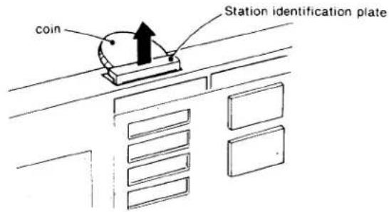
text_image
coin Station identification plate② Pick out the appropriate labels for the pre-memorized stations and affix them to the plate as shown, in the correct order.
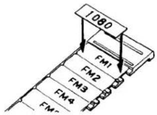
text_image
1080 FM1 FM2 FM3 FM4 FM2② Replace the plate.
Check that the station labels match the pre-memorized stations by tuning in to each station.
REPRODUCTION OF PHONO, CD/AUX AND TAPE PROGRAM SOURCES
Once you familiarize yourself with the operation of FM/AM reception, you can listen to other program sources as follows:
① Set the controls and switches at the initial setting position. (See page 9).
② Select the desired program source as required by using the TAPE MONITOR and FUNCTION switches.
| Program | TAPE MONITOR switch | FUNCTION switches |
| Record playing | Release. | Press PHONO (9). |
| Auxiliary source | Press CD/AUX (0). | |
| Taped program | Depress. | Any |
● Play the program source.
① Adjust the sound quality to your preference.
The TAPE MONITOR switch has priority over the FUNCTION switches.
If the TAPE MONITOR switch is depressed, you cannot listen to the program source selected by the FUNCTION switches.
TAPE RECORDING
① Select the program to be recorded with the FUNCTION switches.
② Release the TAPE MONITOR switch.
③ Adjust the recording level.
④ Start recording.
text_image
LINE IN REC OUT PHONO PHONONote: The VOLUME, BASS, TREBLE and BALANCE controls and the LOUDNESS switch have no effect upon the recording.
Monitoring of a 3-head tape recorder
If your tape recorder has separate record and playback heads, you can monitor the recording results.
Press the TAPE MONITOR switch to monitor the recording results. Press the TAPE MONITOR switch again to release it, and the source sound will be heard. Be sure to keep the monitor switch of the tape recorder in the TAPE position.
FM ANTENNAS
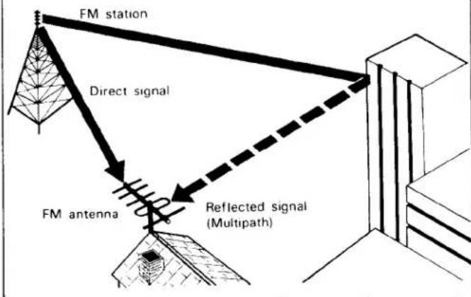
To get the best from your receiver, it is important to use an outdoor antenna. Be sure to pick an outdoor antenna which suits your location. This is determined by the signal strength, the presence of multipath signals*, and the location of the FM stations.
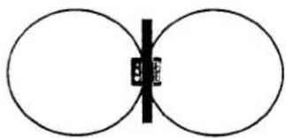
A ribbon dipole antenna picks up signals from both front and rear equally well, but is susceptible to the pickup of extraneous noise.

A Sony table-top type AN-300 helical FM antenna (optional), which incorporates a tuning circuit; has the same pick-up pattern, with equal front and rear sensitivity, as a ribbon dipole antenna, but it is also liable to pick up extraneous noise. When this antenna is used with this receiver, with the antenna's TUNING MODE switch set to AUTO, the antenna is automatically tuned to the same station as the receiver. This type of antenna is convenient when it is not practical to install an FM outdoor antenna and where the signals are sufficiently strong.
natural_image
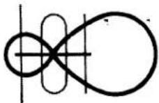
Simple diagram of two overlapping circles with a central vertical line and a small labeled square (no text or symbols)A dipole antenna with reflector has increased sensitivity to front signals and reduced sensitivity to rear signals.
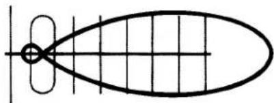
A multi-element type has a narrower pick-up pattern with high frontal sensitivity and superior rejection of rear signals.
natural_image
Pure geometric diagram of an ellipse with internal grid lines and a central circle (no text or symbols)FM antenna installation and orientation
● Install the FM antenna as high as possible, keeping it away from TV antennas or others operating in roughly the same frequency range.
● The antenna should be located on the side of your house away from heavy auto traffic to avoid ignition noise interference.
● To obtain good reception from all directions, the use of a remotely-controlled rotatable antenna, or an omnidirectional antenna which picks up signals equally well in all directions, is recommended.
* Multipath signals reflect from hills or structures, reach the receiving antenna perceptibly later in time and cause severe distortion and complete loss of channel separation. Multipath signals can be avoided to a great extent by using a coaxial cable, and a good directional antenna that is correctly oriented.
text_image
FM station Direct signal FM antenna Reflected signal (Multipath)TROUBLE CHECKS
The following checks will assist in the correction of most problems which you may encounter with your unit. Should any problem persist after you have made these checks, consult your nearest Sony service facility. Before going through the check list below, first refer back to the connection and operating procedures.
OFF-THE-AIR PROGRAMS
STEREO indicator does not light when receiving stereo programs
- Adjust the antenna.
●Press the FM MODE switch.
STEREO indicator flickers
- Adjust the antenna or connect an external FM antenna.
●Press the FM MODE switch to disengage the stereo mode.
The frequency/function display figures do not stop at the desired station during automatic tuning
● The signal strength is too weak for automatic tuning.
Adjust the antenna for optimum reception or tune in the station with the direct access tuning system.
Tuning cannot be done correctly when the PRESET TUNING button is pressed
● Memorize the frequency correctly.
● Install or replace with new batteries for memory back-up.
Incorrect figures appear on the frequency/function display window
● Install the batteries again. (Page 9)
AM stations cannot be tuned in
● The AM channel plan selector at the rear is set incorrectly.
Set the selector correctly according to the AM frequency allocation system of your country. (Page 3)
Severe hum or noise
● Use shielded connecting cords.
● Ground the receiver.
● Avoid long horizontal runs of antenna lead.
- Keep connecting cords (or antenna lead-in) away from transformers or motors, and at least 3 meters (10 feet) from TV sets and fluorescent lights.
- Adjust the antenna.
- Keep the speaker cords, connecting cords and power cords from the ferrite-bar antenna at the rear.
Ignition noise
● Install the outdoor antenna away from heavy traffic.
● Use a shielded or coaxial lead-in for the antenna.
Electrostatic charge
● Ground the receiver.
GENERAL
No audio
- Check speaker and program source connections.
- Check the settings of the TAPE MONITOR switch.
- Check the SPEAKERS switches setting.
● Turn up the volume.
No audio from one channel or unbalanced left and right volume
- Adjust the BALANCE control.
- Check the speaker and input connections of the inoperative channel.
Reversed left and right sound
- Check the speaker cord connection and speaker location.
Lack of bass sound or obscure instrument position
- Check the speaker connection for proper phasing.
Severe hum or noise
● Use shielded connecting cords.
- Keep the connecting cords away from transformers or motors and at least 3 meters (10 feet) from TV sets and fluorescent lights.
● Ground the receiver.
Rustling noise
● Make secure connections.
● Wipe the plugs and jacks with a cloth lightly dampened with methanol.
SPECIFICATIONS
AUDIO POWER SPECIFICATIONS
POWER OUTPUT AND TOTAL HARMONIC DISTORTION:
With 8 ohm loads, both channels driven, from 20 - 20,000 Hz; rated 20 watts per channel minimum RMS power, with no more than 0.08% total harmonic distortion from 250 milliwatts to rated output.
OTHER SPECIFICATIONS
Amplifier section
| Dynamic headroom | 1.4 dB ('78 IHF) |
| Harmonic distortion | Less than 0.08% at rated output |
| Intermodulation (IM) | distortion |
| (60 Hz : 7 kHz = 4 : 1) | Less than 0.08% at rated output |
| Frequency response | PHONO : RIAA equalization curve ±0.5 dBCD/AUXTAPE) 10 Hz - 50 kHz:9dB |
| Residual noise | Less than 200 μV (8 ohms, network A) |
| Damping factor | 30 (8 ohms, 1 kHz) |
| Inputs |
| Sensitivity | Impedance | Maximum input capability (1 kHz) | SiN (weighting network, input level) | |
| PHONO | 2.5 mV | 50 kohms | 150 mV | 74 dB(A, 2.5 mV) |
| CD/AUX TAPE | 150 mV | 50 kohms | — | 90 dB(A, 150 mV) |
Outputs REC OUT
| Voltage 150 mV | |
| Impedance 10 k ohms. | |
| SPEAKER A, B | |
| Accepts speakers of 8 to 16 ohms. | |
| HEADPHONES | |
| Accepts low and high impedance head-phones. | |
| Tone controls | BASS |
| ±8 dB at 100 Hz | |
| TREBLE | |
| ±8 dB at 10 kHz | |
| Loudness (att. 30 dB) | +8 dB at 100 Hz |
FM tuner section
| Tuning range | 87.5 MHz - 108 MHz |
| Antenna terminals | 300 ohms, balanced75 ohms, unbalanced |
| Intermediate frequency | 10.7 MHz |
| Sensitivity at 50 dB quieting | |
| 17.3 dBf, 4 μV (mono) | |
| 38.3 dBf, 45 μV (stereo) | |
| Usable sensitivity | 11.2 dBf, 2 μV (IHF) |
| Signal-to-noise ratio | 75 dB (mono), 70 dB (stereo) |
| Harmonic distortion | 0.2% (mono), 0.3% (stereo) at 1 kHz |
| IM distortion | 0.2% (mono), 0.3% (stereo) |
| Separation | 45 dB at 1 kHz |
| Frequency response | 30 Hz - 15 kHz +0.5 dB |
| Selectivity | 60 dB at 400 kHz |
Capture ratio 1.5 dB
AM suppression ratio 54 dB
Image response ratio 45 dB
IF response ratio 90 dB
Spurious response ratio
70 dB
RF intermodulation 60 dB (IHF)
Auto-tuning threshold
Approx. 45 dBf
AM tuner section
| Tuning range | 530 1,610 kHz (with the AM channel plan selector set at 10 kHz) |
| 522 - 1,602 kHz (with the AM channel plan selector set at 9 kHz) | |
| Antenna | Ferrite-bar antenna |
| External antenna terminal | |
| Intermediate frequency | 450 kHz |
| Usable sensitivity | 300 μV/m, ferrite-bar antenna (at 1,000 kHz) |
| 100 μV, external antenna (at 1,000 kHz) | |
| Signal-to-noise ratio | 54 dB (at 50 mV/m) |
| Harmonic distortion | 0.3% (at 50 mV/m, 400 Hz) |
| Selectivity | 40 dB (10 kHz) |
General
| System | Tuner section: PLL quartz-locked digital synthesizer systemPreamplifier section: low-noise NF type equalizer ampPower amplifier section: quasi-complementary SEPP |
| Power requirements | 120 V ac, 60 HzMemory back-up power: 3 V dc, two batteries, size AA (IEC designation R6)Battery life: approx. 1 year with Sony SUM-3(NS) New Super Batteries (or Eveready Heavy Duty Batteries No. 1215) |
| Power consumption | USA model: 65 wattsCanadian model: 100 watts |
| AC outlets | One switched (100 watts)One unswitched (100 watts) |
| Dimensions | Approx. 430 × 105 × 305 mm (w/h/d) (17 × 4^1/8 × 12^1/8 inches)including projecting parts and controls |
| Weight | Approx. 5.6 kg (12 lbs 5 oz) netApprox. 6.9 kg (15 lbs 3 oz) in shipping car-ton |
| Accessories supplied | |
| FM ribbon antenna (1)Station label (1 set)Sony New Super Batteries SUM-3(NS) (2) | |
| Design and specifications subject to change without notice. | |