
Pro DH-HAC-HDW2802T-Z-A - Sicherheitskamera Dahua Technology - Kostenlose Bedienungsanleitung
Finden Sie kostenlos die Bedienungsanleitung des Geräts Pro DH-HAC-HDW2802T-Z-A Dahua Technology als PDF.


Benutzerfragen zu Pro DH-HAC-HDW2802T-Z-A Dahua Technology
0 Frage zu diesem Gerät. Beantworten Sie die, die Sie kennen, oder stellen Sie Ihre eigene.
Eine neue Frage zu diesem Gerät stellen
Laden Sie die Anleitung für Ihr Sicherheitskamera kostenlos im PDF-Format! Finden Sie Ihr Handbuch Pro DH-HAC-HDW2802T-Z-A - Dahua Technology und nehmen Sie Ihr elektronisches Gerät wieder in die Hand. Auf dieser Seite sind alle Dokumente veröffentlicht, die für die Verwendung Ihres Geräts notwendig sind. Pro DH-HAC-HDW2802T-Z-A von der Marke Dahua Technology.
BEDIENUNGSANLEITUNG Pro DH-HAC-HDW2802T-Z-A Dahua Technology
HDCVI ICR Waterproof Eyeball Camera
1.2.51.32.13026-000
User's Manual V1.0.2
Foreword
General
This user's manual (hereinafter referred to be "the Manual") introduces the functions, installation and operations of the camera.
Safety Instructions
The following categorized signal words with defined meaning might appear in the Manual.
| Symbol | Note |
| DANGER | Indicates a high potential hazard which, if not avoided, will result in death or serious injury. |
| WARNING | Indicates a medium or low potential hazard which, if not avoided, could result in slight or moderate injury. |
| CAUTION | Indicates a potential link which, if not avoided, may result in property damage, data loss, lower performance, or unpredictable result. |
| ELECTRICITY | Indicates dangerous high voltage. Take care to avoid caring into contact with electricity. |
| LASER BEAM | Indicates a laser radiation hazard. Take care to avoid exposure is a laser beam. |
| ESO | Electrostatic Service Devices. Indicates a device that a sensitive to electrostatic discharge. |
| TIPS | Provides methods to play a problem or save you time. |
| NOTE | Prevides additional information as the emphasis and supplement to the leaf. |
About the Manual
- The Manual is for reference only, if there is inconsistency between the Manual and the actual product, the actual product shall govern. - All the designs and software are subject to change without prior written notice. The product updates might cause some differences between the actual product and the Manual. Please contact the customer service for the latest program and supplementary documentation.
- There still might be deviation between the actual value of some data and the value provided, if there is any doubt or dispute, please refer to our final explanation.
- Please contact the supplier or customer service if there is any problem occurred when using the device.
- We are not liable for any loss caused by the operations that do not comply with the Manual.
- All trademarks, registered trademarks and the company names in the Manual are the properties of their respective owners.
- Please visit our website or contact your local service engineer for more information.
- If there is any uncertainty or controversy, please refer to our final explanation.
1 Introduction
1.1 General
This series of products comply with the HDCVI standard and support the transmission of audio, video and control signal over coaxial cable. They produce video signal with up to 6MP and 4K resolution and require XVR device that comply with HDCVI standard to achieve high speed, long distance and zero lag transmission of the signal. They are applicable to cover the high definition monitoring needs for locations with complex lighting conditions, such as financial center, telecom site, supermarket, hotel, government, school and factory.
1.2 Features
- Support over 300 meter real-time transmission of audio, video and control signal from RG59 cable.
- Excellent low-light performance with 2D/3D noise reduction.
- Adopt motorized vari-local lens, support zoom/focus adjustment on XVR device (available on select models).
- Auto switch from vivid color images by day and black-and-white images at night with ICR.
- Provide clear IR imaging by adjusting IR light to moving objects with smart IR.
- Configuring devices easily with OSD, the OSD supports various customized effects.
- Support switching output mode between CVI/CVBS/AHD/TVI through DIP switch.
- Operate on DC 12V ± 30%/AC24V ± 30% with wide voltage range (available on select models)
- Serve as a DC 12V 2W power source (available on select models) - IP67 rated.
2 Design
2.1 Dimension
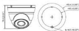
Figure 2-1 Model A (mm [in])
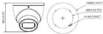
Figure 2-2 Model B (mm [in])
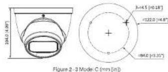
text_image
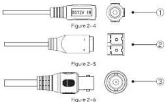
Figure 2 - 3 Mode C (mm [in]) 104.0 ± 0.05 3-44.5 [±0.18°] ±122.0 [±4.8°] ±64.0 [±3.31°]2.2 Cable
text_image
BG12V IN Figure 2-4 + Figure 2-5 Figure 2-6 ① ② ③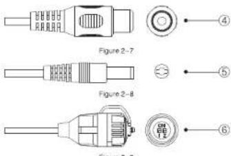
text_image
Figure 2-7 Figure 2-8 Figure 3-BFor more information about cable ports, see Table 2-1; for the operation method of ©(DIP switch), see Table 2-2.
| No. | Port Name | Function |
| 1 | DC 12V Power Input | Inputs DC 12V power. Please be sure to supply power as instructed in the Manual.AoutflowDevice abnormality or damage could occur if power is not supplied correctly |
| 2 | DC 12V or AC 24V Power Input | Inputs DC 12V or AC 24V power. Please be sure to supply power as instructed in the Manual.AoutflowDevice abnormality or damage could occur if power is not supplied correctly. |
| 3 | Video Output | Connects to XVR to output video signal. |
| 4 | Audio Input | Connects to sound-pick-up devices to receive audio signal. |
| 5 | Power Output | Supplies DC12V 2W power. |
| 6 | DIP Switch | Dial switches to change output mode. Switch up indicates 'ON', switch down indicates 'OFF'. |
Table 2-1
| Switch1 | Switch2 | Output Mode |
| OFF | OFF | CVI |
| ON | ON | CVBS |
| ON | OFF | AHD |
| OFF | ON | TVI |
Table 2-2
3 Installation
CAUTON
- Make sure the mounting surface is strong enough to hold at least three times of the camera weight.
- The following figure is for reference only, actual product shall prevail. For the installation diagram and item list of model A, see Figure 3-1 and Table 3-1, for those of model B and model C, see Figure 3-2 and Table 3-2.
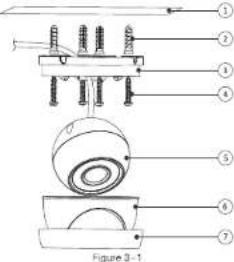
text_image
Figure 3-1| No. | Item | No. | Item | No. | Item | No. | Item |
| 1 | Mounting surface | 2 | Expansion bolt | 3 | Pedestal | 4 | Self-capingscrew |
| 5 | Device | 6 | Enclosure | 7 | Racking |
Table 3-1
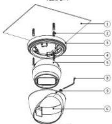
text_image
Exploded view diagram of a mechanical assembly with numbered parts for identificationFigure 3-2
| No. | Item | No. | Item | No. | Item | No. | Item |
| 1 | Mounting surface | 2 | Expansion bolt | 3 | Pedestal | 4 | Self-capping screw |
| 5 | Device | 6 | Enclosure | 8 | Wrench | 9 | Locking screw |
Table 3-2
Step 1 Find the mounting template sticker from the accessory pack and stick it to the mounting surface ①
Step 2 Drill screw holes (and the cable outlet hole if it needs to go through the mounting surface) on the mounting surface as indicated on the mounting template, then insert expansion bolts; from the accessory pack in the screw holes.
Step 3 The disassemble way of model A is different from which of model B and model C.
- For model A, hold the pedestal; slightly and keep the device; upward, rotate the fixing ring; counterclockwise until you can detach it from above, and then take off the pedestal.
- For model B and model C, loosen the locking screw with the supplied wrench and take the pedestal off.
Step 4 Adjust the location of the pedestal according to cable outlet requirement (top out or side out), then pull the cable out through mounting surface or the side wire tray. Align the screw holes on the pedestal to those on the mounting surface, then put in and fasten the supplied self-tapping screws to attach the device to the mounting surface.
Step 5 Connect the camera to power source and the XVR device, and the live view screen will be displayed.
Step 6 The assemble and adjustment way of model A is different from which of model B and model C.
- For model A, put the fixing ring⑦ back to hold the enclosure ⑧, leave some spaces enough for you to adjust the device⑨. Aim the lens to the ideal angle(see Figure 3-3) and lasten the fixing ring⑩.
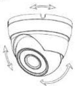
Figure 3-3
- For model B and model C, put the enclosure® back on and adjust the locking screw® to hold it, leave some spaces enough for you to adjust the device®. Aim the lens to the ideal angle and adjust the locus until you get clear image (see Figure 3-4) and fasten the locking screw®.

Figure 3-4
(1) TPS
- For model B and model C, it's easier to fit the enclosure to the
pedestal3 if you put the higher end in first and then the lower end
- For the models with var-focal lens, you can also adjust the focus through XVR device.

Configuration
Power up the camera and connect it to XVR device with coaxial cable, then the live view screen is displayed. The following instructions will guide you to configure your camera.
NOTE
The number of the coaxial port on XVR will display at the lower left corner of the live view window to indicate the corresponding camera.
4.1 Opening Main Menu
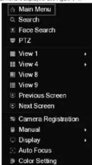
Step 1 In the live view screen interface, right-click anywhere on the screen. The shortcut menu is displayed. See Figure 4-1.
text_image
Main Menu Search Face Search PTZ View 1 View 4 View 8 View 9 Previous Screen Next Screen Camera Registration Manual Display Auto Focus Color SettingFigure 4-1
Step 2 Click Main Menu
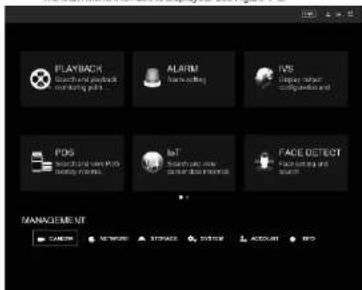
The Man Menu interface is displayed. See Figure 4-2.
text_image
PLAYBACK Search and productivity on trading pad ALARM Home editing IVS Display response on platformed list PDS Search and productivity on trading pad BIT Search and productivity on platformed list FACE DETECT Search and productivity MANAGEMENT CAMER NETWORK STORAGE SISTER ACCOUNT INFOFigure 4-2
NOTE
Right-click anywhere on the screen to return to the previous menu until you go back to the live view screen interface
4.2 Setting Audio Input
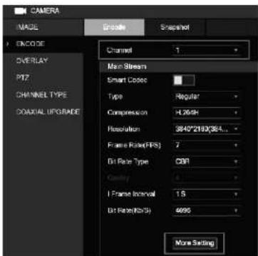
Step 1 In the Main Menu interface (Figure 4–2), select CAMERA > ENCODE > Encode
The Encode setting interface is displayed. See Figure 4-3.
text_image
CAMERA IMAGE Engine Spread Snapshot ENCODE OVERLAY PI7 CHANNEL TYPE COADUAL UPGRADE Channel 1 Main Stream Smart Codec Type Regular Compression H.269H Resolution 3840*2160/364... Frame Rate (RPS) 7 Bit Rate Type C001 Cavity 4 I Frame Interval 1.5 Bit Rate (KPS) 4000 More SettingFigure 4-3
Step 2 In the Channel list, select the camera that you want to configure according to the coastal port number.
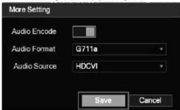
Step 3 In the Main Stream column, click More Setting The More Setting interface is displayed. See Figure 4-4.
text_image
More Setting Audio Encode Audio Format G711a Audio Source HDCVI Save CancelFigure 4-4
Step 4 In the More Setting interface, you can configure the audio settings.
- Enable Audio Encode function.
- In the Audio Format list, leave to the default.
- In the Audio Source list, select HDCVI.
Step 5 Click Save to save the settings.
The Encode setting interface is displayed.
Step 6 In the Encode setting interface (Figure 4-3), click Apply.
4.3 Operating OSD Menu
Step1 In the live view screen interface, right-click within the live view window of the camera that you want to configure.
The shortcut menu (Figure 4-1) is displayed.
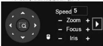
Step 2 Click PTZ
The PTZ setting interface is displayed. See Figure 4-5
text_image
Speed 5 - Zoom + - Focus + - Iris +Figure 4-5
Step 3 Click to see more options. See Figure 4-6.
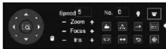
Figure 4-6
Step 4 Click
The MENU OPERATION panel is displayed. See Figure 4-7. The OSD menu of the corresponding camera is displayed on the live view screen.

text_image
MENU OPERATION Enter CancelFigure 4-7
For the function of the buttons in the MENU OPERATION panel, see Table 4-1.
| Button | Function | Button | Function |
| Enter | Enter or confirm an item | Select item | |
| Close | Exit OSD menu | Change item value |
Table 4-1
If there is "←" as the value of an OSD item, click Enter to go to the next level of this item. Click Return to go back to the previous level. Clicking Cancel is to exit OSD menu without saving the modifications.
NOTE
Interfaces of different XVR may vary, the actual product shall prevail. The OSD menus of different cameras may vary, the actual product shall prevail.

Maintenance
CAUTEN
In order to maintain the image quality and proper functioning of the device, please read the following maintenance instructions carefully and hold rigid adherence
Maintaining Lens and Mirror Surface
Do not touch the image sensor directly. The lens and mirror surface are covered with antireflection coating, which could be contaminated or damaged and result in lens scratches or haze image when being touched with dust, grease, fingerprints and other similar substances. Dust and dirt could be removed with air blower, or you can wipe the lens gently with soft cloth that moistened with alcohol.
Maintaining Device Body
Device body can be cleaned with soft dry cloth, which can also be used to remove stubborn stains when moistened with mild detergent. To avoid possible damage on device body coating which could cause performance decrease, do not use volatile solvent such as alcohol, benzene, difluent and so on to clean the device body, nor can strong, abrasive detergent be used