
DH-HAC-HDBW1220R-VF - Sicherheitskamera Dahua Technology - Kostenlose Bedienungsanleitung
Finden Sie kostenlos die Bedienungsanleitung des Geräts DH-HAC-HDBW1220R-VF Dahua Technology als PDF.


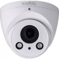
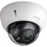
| Produkttyp | HDCVI Sicherheitskamera |
| Modell | DH-HAC-HDBW1220R-VF |
| Marke | Dahua Technology |
| Bildsensor | Hochleistungs-CMOS, Megapixel |
| Auflösung | 720P / 1080P / 4M (abhängig von Variante) |
| Videoausgang | HDCVI HD/SD umschaltbar |
| ICR (Tag/Nacht) | Ja, automatischer ICR-Schalter |
| Smart IR | Ja |
| DWDR | Ja (Digital Wide Dynamic Range) |
| OSD-Menü | Ja, einstellbar über Koaxialsteuerung |
| Stromversorgung | DC 12V |
| Schutzart | IP67, IK10 |
| Gehäusematerial | Metallgehäuse mit Kuppelabdeckung |
| Abmessungen (Modell A) | Siehe Benutzerhandbuch (Abbildung 2-1) |
| Abmessungen (Modell B) | Siehe Benutzerhandbuch (Abbildung 2-2) |
| Gewicht | ca. 500 g (Schätzung) |
| Übertragungsentfernung | 720P: >800 m über RG59; 1080P/4M: >500 m über RG59 |
| Betriebstemperatur | -40 °C bis +60 °C (geschätzt) |
| Luftfeuchtigkeit | <95% (nicht kondensierend) |
| Reinigungshinweise | Weiches, trockenes Tuch verwenden; bei Verschmutzung mildes Reinigungsmittel; alkoholgetränktes Tuch für Linse; kein Benzol oder Verdünner |
| Sicherheitshinweise | Nur von Fachpersonal installieren; Gerät nicht zerlegen; Netzteil gemäß SELV; Überspannungsschutz empfohlen |
| Reparatur | Keine vom Benutzer reparierbaren Teile; wenden Sie sich an den Kundendienst |
| Anwendungsbereiche | Laden, Supermarkt, Café, Schule, Hotel, Büro, Restaurant, Garten, Parkplatz |
| Zubehör im Lieferumfang | Befestigungsschrauben, Dübel, Inbusschlüssel, Kurzanleitung (geschätzt) |
| Garantie | 2 Jahre (typisch für Dahua) |
Häufig gestellte Fragen - DH-HAC-HDBW1220R-VF Dahua Technology
Benutzerfragen zu DH-HAC-HDBW1220R-VF Dahua Technology
0 Frage zu diesem Gerät. Beantworten Sie die, die Sie kennen, oder stellen Sie Ihre eigene.
Eine neue Frage zu diesem Gerät stellen
Laden Sie die Anleitung für Ihr Sicherheitskamera kostenlos im PDF-Format! Finden Sie Ihr Handbuch DH-HAC-HDBW1220R-VF - Dahua Technology und nehmen Sie Ihr elektronisches Gerät wieder in die Hand. Auf dieser Seite sind alle Dokumente veröffentlicht, die für die Verwendung Ihres Geräts notwendig sind. DH-HAC-HDBW1220R-VF von der Marke Dahua Technology.
BEDIENUNGSANLEITUNG DH-HAC-HDBW1220R-VF Dahua Technology
HDCVI Camera User's Manual
Version 1.0.1
Table of Contents
1 General Introduction....
1.1 Overview
1.2 Features....
2 Device Framework 2
3 Installation....错误!未定义书签。
4 Menu 6
4.1 HCVR Settings 6
4.2 Menu Operation 6
Welcome
Thank you for purchasing our HDCVI camera!
This user's manual is designed to be a reference tool for your system.
Please read the following safeguard and warnings carefully before you use this series product!
Please keep this user's manual well for future reference!
Important Safeguards and Warnings
1. Electrical safety
All installation and operation here should conform to your local electrical safety codes.
Please check if the power supply is correct before operating the device.
The power shall conform to the requirement in the SELV (Safety Extra Low Voltage) and the Limited power source is rated DC 12V or AC24V in the IEC60950-1. (Power supply requirement is subject to the device label).
Please install easy-to-use device for power off before installing wiring, which is for emergent power off when necessary.
Please prevent the line cord from being trampled or pressed, especially the plug, power socket and the junction from the device.
Note: Do not connect these two power supplying sources to the device at the same time; it may result in device damage!
We assume no liability or responsibility for all the fires or electrical shock caused by improper handling or installation.
We are not liable for any problems caused by unauthorized modification or attempted repair.
2. Environment
Please don't aim the device at strong light (such as lighting, sunlight and so on) to focus; otherwise it may cause overexposure (It is not the device malfunction), which will affect the longevity of CCD or CMOS.
Please transport, use and store the device within the range of allowed humidity and temperature.
Please don't keep the device in a place which is wet, dusty, extremely hot, and extremely cold and with strong electromagnetic radiation or unstable lighting.
Please do not allow water and other liquid falling into the camera in case that the internal components are damaged.
Please do not allow rain or damp to the indoor device in case fire or lightning may occur.
Please keep the sound ventilation in case of heat accumulation.
Please pack the device with standard factory packaging or material with same quality when transporting the device.
Heavy stress, violent vibration or water splash are not allowed during transportation, storage and installation.
3. Operation and Daily Maintenance
Please do not touch the heat dissipation component of the device directly in order to avoid scald.
Please do not dismantle the device; there is no component which can be fixed by users themselves in the machine. It may cause water leakage or bad image for the device due to unprofessional dismantling. It is recommended to use the device with thunder proof device in order to improve thunder proof effect. The grounding holes of the product are recommended to be grounded to further enhance the reliability of the camera.
Do not touch the CCD (CMOS) optic component directly. You can use the blower to clean the dust or dirt on the lens surface. Please use a dry cloth wetted by alcohol to wipe away the dust gently if it is necessary to clean.
Always use the dry soft cloth to clean the device. If there is too much dust, please use the water to dilute the mild detergent first and then use it to clean the device. Finally use the dry cloth to clean the device. Don't use volatile solvent like alcohol, benzene, thinner and etc or strong detergent with abrasiveness, otherwise it will damage the surface coating or reduce the working performance of the device.
Dome cover is an optical device, please don't touch or wipe cover surface directly during installation and use, please refer to the following methods to deal with once dirt is found:
Stained with dirt
Use oil-free soft brush or hair dries to remove it gently.
Stained with grease or fingerprint
Use soft cloth to wipe the water drop or oil gently to make it dry, then use oil-free cotton cloth or paper soaked with alcohol or detergent to wipe from the lens center to outward. It is ok to change the cloth and wipe several times if it is not clean enough.
Warning
Please use the standard accessories provided by manufacturer and make sure the device is installed and fixed by professional engineers.
Please prevent the device surface from the radiation of laser beam when using laser beam device.
Please do not provide two or more power supply modes for the device, otherwise it may cause damage to the device.
Statement
Please refer to the actual product for more details; the manual is just for reference.
The manual will be regularly upgraded according to the product update; the upgraded content will be added in the manual without prior announcement.
Please contact the supplier or customer service if there is any problem occurred when using the device.
Please contact the customer service for the latest procedure and supplementary documentation.
There may be deviation between the actual value of some data and the value provided in the manual due to the reasons such as the real environment is not stable and so on. Please refer to the company's final explanation if there is any doubt or dispute.
The company is not liable for any loss caused by the operation which is not followed by the manual.
1 General Introduction
1.1 Overview
This series HDCVI camera conforms to the HDCVI standard. It supports video signal high-speed long distance transmission without any delay. It can be controlled by the DVR conforming to the HDCVI.
1.2 Features
● High-performance CMOS image sensor, megapixel definition.
● Support HD video, control signal coaxial transmission.
- For 720P series, support RG59 coaxial cable transmission without any loss. The distance is over 800m. For 1080P, 4M series, support RG59 coaxial cable transmission without any loss. The distance is over 500m.
• Support HDCVI HD/SD output.
● Support ICR switch to realize surveillance both in the daytime and at night.
● Support OSD menu adjustment parameters.
● Support smart IR function.
• Support DWDR function.
● Support High speed, long distance real-time transmission.
● Support DC12V power supplying.
● Support IP67 and IK10 compliance.
- It can be applied to the various scenes such as store, supermarket, coffee shop, school, hotel, office, restaurant, garden, parking lot and etc.
2 Device Framework
See Figure 2-1 for the dimension of model A.
![109.9 [4.33"] 81.0 [3.19"] Ø109.9 [4.33"] Ø98.2 [3.87"] 3-Ø4.7 [0.19]](/content/2026/05/813000/images/8e5b6f098d2b14633c4fd750f58e104b36670dcf1e52c5447db59739b06dfc32.jpg)
Figure 2-1
See Figure 2-2 for the dimension of model B.
![122.0 [4.8°] 88.9 [3.5°] Ø122.0 [Ø4.8°] 3-Ø4.5 [Ø0.18°] Ø110.0 [Ø4.33°]](/content/2026/05/813000/images/35dc725eb7d784511d4770bc9b969ffc82f7b4efce681398654116d8ad88b44a.jpg)
Figure 2-2
Note
Video output port outputs HDCVI HD video by default. HD/SD output can be switched via PFM820 (UTC Controller) or OSD menu → Advanced → Video Output.
3 Installation
Important
- Before the installation, please make sure the installation surface can sustain at least 3X weight of the bracket and the camera.
Model A
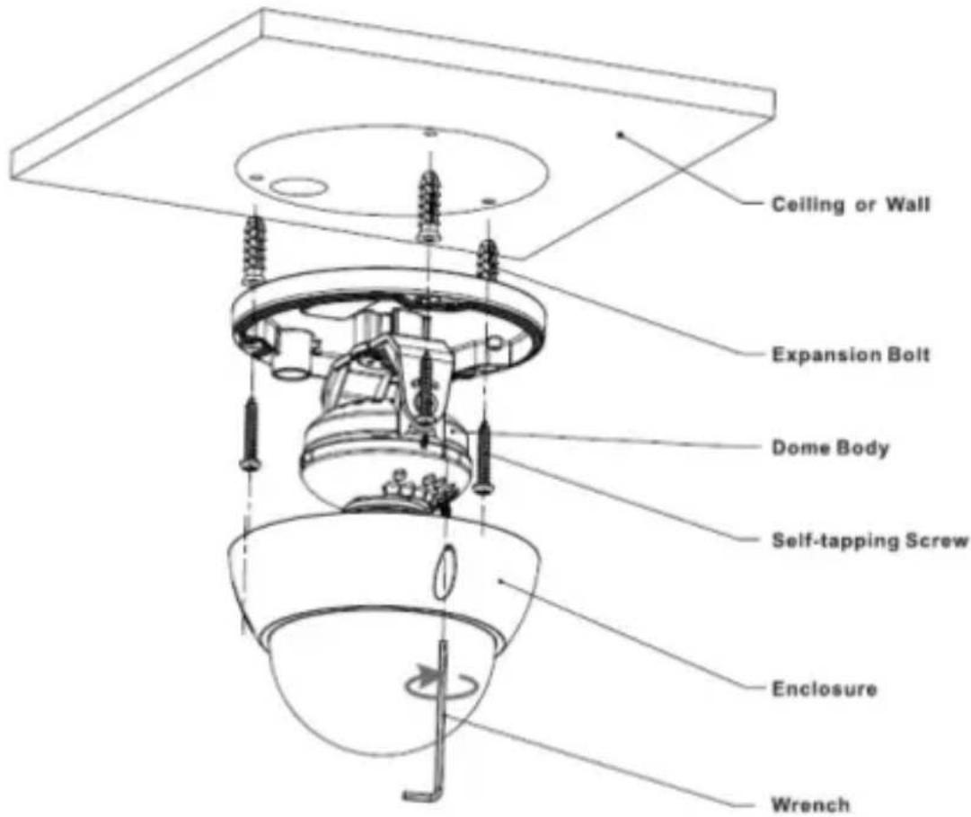
Figure 3-1
Step 1
Use wrench to loosen three fixing screws on the enclosure and remove the dome cover.
Step 2
Confirm the installation location and dig holes on the installation surface.
Step 3
Use tools to put the expansion bolts into the installation holes and fix them firmly.
Step 4
Adjust the location of the device installation pedestal; pull the cable through the hole on the installation surface. Align the bolt fixing holes of the device pedestal with the expansion bolt fixing holes on the installation surface; insert the self-tapping screws into the expansion bolts and fasten them firmly to fix the pedestal on the installation surface.
Step 5
Connect the video output port of the device cable to the back-end encoding device, and make the power port connect to power.
Step 6
Adjust lens angle to a proper monitoring location after displaying image on the back-end encoding device (if it is model B, it can adjust focal length to make image clear via focusing tool). See Figure 3-2.
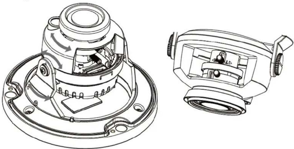
Figure 3-2
Step 7
Lock the screws firmly and fix the dome enclosure on the pedestal.
So far, camera installation and cable connection are completed; you can check monitoring video via back-end coding device.
4 Menu
4.1 HCVR Settings
This HDCVI camera series can adjust OSD menu via coaxial control. After connected the camera to the HDCVI series HCVR, from Main Menu->Setting->System->PTZ, you need to select the channel number for access and set control mode as HDCVI and the protocol as HD-CVI. Click "Save" button to save current setup. See Figure 4-1.
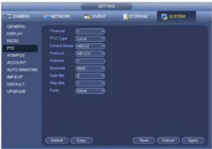
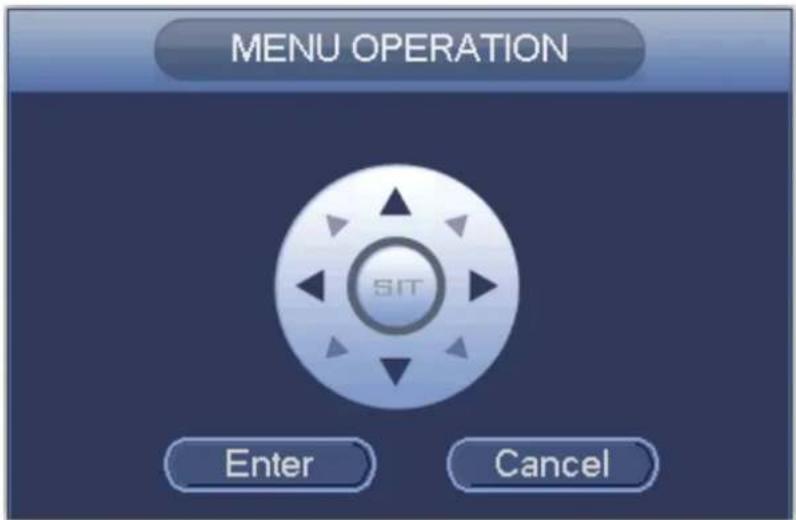
Figure 4-3
See Sheet 4-1 for the details of button functions.
| Button | Function | |
 | Open menu | |
 | Select menu item | |
 | Select menu value | |
Sheet 4-1
If there is “◀”, click the “Confirm” button in “Menu Operation” interface to go to the 2nd menu. Click “Return” button to go back to the previous menu interface.
Please use an UTC controller or enter the OSD menu for to switchover between HD & SD video output.
Note
- This manual is for reference only. Slight difference may be found in the user interface.
- All the designs and software here are subject to change without prior written notice.
- All trademarks and registered trademarks mentioned are the properties of their respective owners.
- If there is any uncertainty or controversy, please refer to the final explanation of us.
- Please visit our website or contact your local service engineer for more information.



- TABLE OF CONTENTS
- WELCOME
- IMPORTANT SAFEGUARDS AND WARNINGS
- ELECTRICAL SAFETY
- ENVIRONMENT
- OPERATION AND DAILY MAINTENANCE
- WARNING
- STATEMENT
- 1 GENERAL INTRODUCTION
- 1.1 OVERVIEW
- 1.2 FEATURES
- 2 DEVICE FRAMEWORK
- NOTE
- 3 INSTALLATION
- IMPORTANT
- MODEL A
- STEP 1
- STEP 2
- STEP 3
- STEP 4
- STEP 5
- STEP 6
- STEP 7
- 4 MENU
- 4.1 HCVR SETTINGS
Marke : Dahua Technology
Modell : DH-HAC-HDBW1220R-VF
Kategorie : Sicherheitskamera