CELL10T/EN - Lautsprecher Penton - Kostenlose Bedienungsanleitung
Finden Sie kostenlos die Bedienungsanleitung des Geräts CELL10T/EN Penton als PDF.


Benutzerfragen zu CELL10T/EN Penton
0 Frage zu diesem Gerät. Beantworten Sie die, die Sie kennen, oder stellen Sie Ihre eigene.
Eine neue Frage zu diesem Gerät stellen
Laden Sie die Anleitung für Ihr Lautsprecher kostenlos im PDF-Format! Finden Sie Ihr Handbuch CELL10T/EN - Penton und nehmen Sie Ihr elektronisches Gerät wieder in die Hand. Auf dieser Seite sind alle Dokumente veröffentlicht, die für die Verwendung Ihres Geräts notwendig sind. CELL10T/EN von der Marke Penton.
BEDIENUNGSANLEITUNG CELL10T/EN Penton
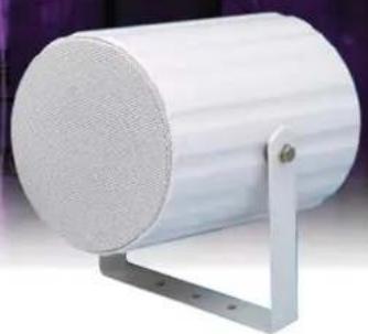
METAL SOUND PROJECTORS
CELL10T/EN
CELL1OT/ENC
natural_image
White cylindrical industrial component mounted on a metal bracket (no visible text or symbols)
text_image
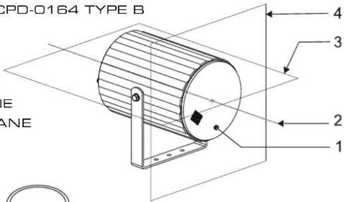
EN54-24INSTALLATION INSTRUCTIONS
EN54-24:2008
Certificate No: 0359-CPD-0164 TYPE B
- LOUDSPEAKER ENCLOSURE
- REFERENCE AXIS
- REFERENCE PLANE
- HORIZONTAL PLANE
text_image
CPD-0164 TYPE B E ANE 1 2 3 4Circuit Diagram
text_image
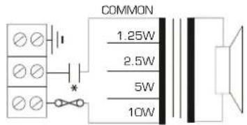
COMMON 1.25W 2.5W 5W 10WCELL10T/EN
CELL10T/ENC
* with capacitor
natural_image
Isometric line drawing of a structural frame with two supports and a vertical panel (no text or symbols)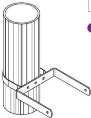
natural_image
Technical line drawing of a cylindrical mechanical bracket with two metal arms (no text or symbols)
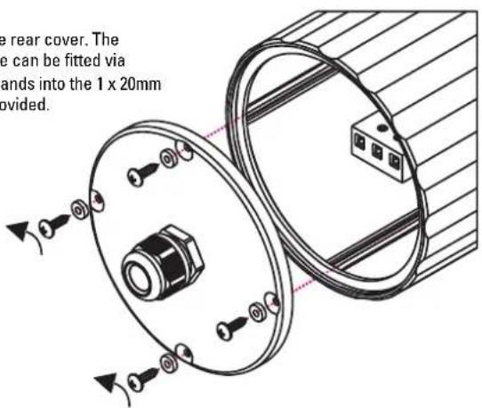
2. Remove the rear cover. The installation cable can be fitted via suitably rated glands into the 1 x 20mm gland entries provided.
text_image
e rear cover. The e can be fitted via ands into the 1 x 20mm vided.
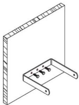
1. Remove the "U" bracket from the speaker. Align the bracket and mark the fixing points. Fix the bracket using suitable fixings (Not supplied).
natural_image
Technical line drawing of a circular mechanical component with internal components and mounting holes (no text or symbols)10W 5W 2.5W 1.25W

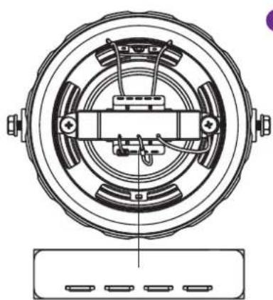
3. The cable can then be terminated into the terminal block fitted to the rear of the speaker. The terminals are suitable to take "loop in" "loop out" connections up to 2.5mm per core.
4. Select the desired tapping.
5. Re-fit the rear cover ensuring that the gasket is in place and that the screw fittings are fitted with their rubber washers to ensure the rear cover retains its weatherproof rating.
natural_image
Simple line drawing of a metal frame with a vertical rod and handle (no text or symbols)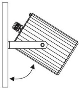
natural_image
Diagram of a mechanical lever mechanism with rotating arm and pivot point (no text or symbols)
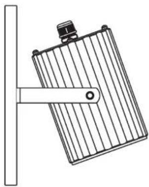
6. Re-fit the speaker to the "U" bracket. Position the speaker to the desired angle then tighten the fixings to secure in place.