PBC6T/ENC - Lautsprecher Penton - Kostenlose Bedienungsanleitung
Finden Sie kostenlos die Bedienungsanleitung des Geräts PBC6T/ENC Penton als PDF.


Benutzerfragen zu PBC6T/ENC Penton
0 Frage zu diesem Gerät. Beantworten Sie die, die Sie kennen, oder stellen Sie Ihre eigene.
Eine neue Frage zu diesem Gerät stellen
Laden Sie die Anleitung für Ihr Lautsprecher kostenlos im PDF-Format! Finden Sie Ihr Handbuch PBC6T/ENC - Penton und nehmen Sie Ihr elektronisches Gerät wieder in die Hand. Auf dieser Seite sind alle Dokumente veröffentlicht, die für die Verwendung Ihres Geräts notwendig sind. PBC6T/ENC von der Marke Penton.
BEDIENUNGSANLEITUNG PBC6T/ENC Penton
INSTALLATION INSTRUCTIONS
EN54-24:2008
Certificate No: 0359-CPD-0167 TYPE A
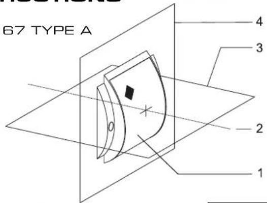
- LOUDSPEAKER ENCLOSURE
- REFERENCE AXIS
- REFERENCE PLANE
- HORIZONTAL PLANE
text_image
67 TYPE A 1 2 3 4Circuit Diagram
text_image
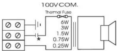
100VCOM. Thermal Fuse 6W 3W 1.5W 0.75W 0.25WPBC6T/EN
PBC6T/ENC
* with capacitor
natural_image
Isometric line drawing of a curved mechanical component mounted on a rectangular base (no text or symbols)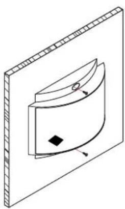
natural_image
Isometric line drawing of a curved mechanical component mounted on a rectangular base (no text or symbols)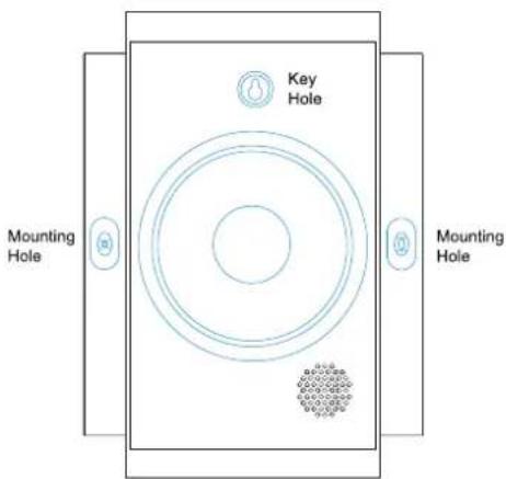
text_image
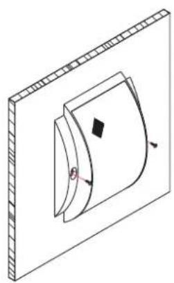
Key Hole Mounting Hole Mounting Hole- Decide on the speaker orientation and place the speaker on a flat surface. It can be installed in any orientation as well as horizontally on a ceiling if required. Mark through the mounting holes in order to position the fixing points which will be 210mm apart. A "Picture Hook" type mounting is also provided which is located at the top section of the speaker. See drawing marked "Key Hole". Prepare the surface to take suitable fixings (Not included).
- If 20mm cable glands are to be used then the speaker cabinet can be drilled using a suitable drill bit. Make sure you place the cable entry in a location that will not cause the cable to be blocked or restricted by any internal components. If you are not using cable glands the back of the speaker cabinet has 2 x "knock out" tabs in the top and side which when removed will allow the speaker cable to pass between the speaker and mounting surface.
text_image
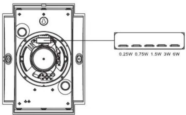
0.25W 0.75W 1.5W 3W 6W- Connect the speaker cable into the 3 way terminal block located on the cabinet. Select your required tapping by moving the white lead to your chosen tapping on the transformer. All tappings are marked on top of the transformer.
natural_image
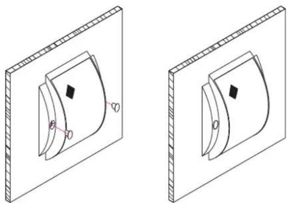
Two isometric diagrams of a curved mechanical component mounted on a rectangular plate, with no visible text or symbols.- Fix the speaker cabinet to the wall using suitable fixings (not provided).
- Fit the 2 x removable covers over the fixing holes..