DVI-HDCP-TP-TX50 - Audio-/Videoverlängerung Lightware - Kostenlose Bedienungsanleitung
Finden Sie kostenlos die Bedienungsanleitung des Geräts DVI-HDCP-TP-TX50 Lightware als PDF.


Benutzerfragen zu DVI-HDCP-TP-TX50 Lightware
0 Frage zu diesem Gerät. Beantworten Sie die, die Sie kennen, oder stellen Sie Ihre eigene.
Eine neue Frage zu diesem Gerät stellen
Laden Sie die Anleitung für Ihr Audio-/Videoverlängerung kostenlos im PDF-Format! Finden Sie Ihr Handbuch DVI-HDCP-TP-TX50 - Lightware und nehmen Sie Ihr elektronisches Gerät wieder in die Hand. Auf dieser Seite sind alle Dokumente veröffentlicht, die für die Verwendung Ihres Geräts notwendig sind. DVI-HDCP-TP-TX50 von der Marke Lightware.
BEDIENUNGSANLEITUNG DVI-HDCP-TP-TX50 Lightware

Quick Start Guide
DVI-HDCP-TP-TX50, -TX100R
DVI-HDCP-TP-RX50,-RX100R
HDMI-TP-TX50,-TX100R,-TX200R
HDMI-TP-RX50R,-RX100R,-RX100RA,-RX200R
Important safety instructions
Please read and keep the information in the attached safety instructions supplied with the product before start using the device.
Introduction
The Lightware HDMI- and DVI-HDCP-TP series extenders can transmit HDMI or DVD signals over two CATx cables. They fully support HDMI 1.3a signals with or without HDCP encryption. Most of the models support RS-232 transmission and HDMI-TP-RX10RA de-embeds digital audio from the HDMI stream and outputs via its S/PDIF connector.
Box contents

Extender unit 12V DC power adaptor
with interchangeable plugs

Additional jumper (red) for
remote power sellings

Safety and warranty info.
Quick Start Guide
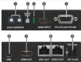
Front and rear views - Transmitter Legend - Transmitter
text_image
EDID ADDRESS HDMI INPUT RS-232 pass through USB HDMI OUT DDC OUT VIDEO OUT 12V 1A DC① For lower resolutions, with a maximum pixel clock frequency of 165 MHz and g PS-232 transmission and remote power is not necessary; one CAT cable is enough - connected to VIDEO OUT.
1 EDID The rotary switches select one of the EDID memory rotary switches addresses
2 Learn button Stores the EDID of the display device attached to the output in the selected memory address, or toggle LED functions.
3 Status LEDs The LEDs give feedback about the state of units and video signal.
4 HDMI input Connect one HDMI cable between the HDMI source and the transmitter unit.
5 RS-232 port S-cole D-sub female connector. Connect a serial cable between the transmitter unit and the desired serial device
USB port USB interface for firmware upgrade and LDC conn
HDMI output Connect one HDMI cable between the local display device and the transmitter unit.
8 CATx outputs Connect one or two CATx cables between the transmitter and the receiver (or Lightwave Hybrid Matrix equipped with twisted pair input cards).
9 DC 12V input Connect the output of the supplied 12V DC power adaptor or use Lightware's rack mountable power supply unit.
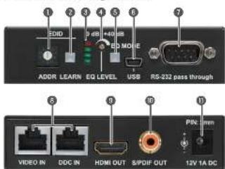
Front and rear views - Receiver Legend - Receiver
text_image
1 2 3 4 5 6 7 8 EDIO 9 dB 10 dB 11 ED MOIE ADDR LEARN EQ LEVEL USB RS-232 pass through VIDEO IN DDC IN HDMI OUT S/PDIF OUT 12V 1A DC PINS 1mmThe extenders do not have networking capabilities. Do not connect the RJ45 parts of the extenders to a Local Area Network device or a PC. Doing so may damage the unit!
1 EDID rotary switch The rotary switch selects one of the EDID memory addresses
2 Learn button Stores the EDID of the display device attached to the output
In the selected memory address, or toggle LED functions.
GAMINO LEDO 110 LEDO GND signal.
EQ level adjust The potentiometer can be used to precisely set the right amount of equalization in manual EQ mode.
EQ mode selector button Toggles between automatic and manual EQ mode. The EQ mode status LEDs indicate which mode is currently active.
USB port USB interface for firmware upgrade and LOC connection.
RS-232 port S-cole D-sub male connector. Connect a serial cable
between the transmitter unit and the desired serial device
- DATA input commands include the two DATA commands by various the subscribers and the receiver (or Lightware Hybrid Matrix equipped with twisted pair output cards).
9 HDMI output Connect one HDMI cable between the local display device
and the transmitter unit,
SPDIF output Standard RCA receptacle for digital coastal audio output
DC 12V Input Connect: the output of the supplied 12V DC power scopor or use Lightware's rack mountable power supply unit
Status LEDs
| RX10RA, RX20R and RX20R | ||
| ON | BLKING | |
| LED1 | HDCP-encrypted content | Selected EDID is invalid |
| LED2 | HDMI signal is present | Selected EDID is valid |
| LED3 | Signal detected | Hotplug detected on HDMI OUT(1) |
| LED4 | TX: Auto EQ mode is ON TX: Source connected | RX100:-RX200: Hotplug detected on OUT2 TX200: Hotplug detected on CATx |
| RX100R | TX100R | |||
| ON | BLINKING | ON | BLINKING | |
| LED1 | Manual cableEQ is ON | Firmware main version | Selected EDIDis invalid | EDID teamfailure |
| LED2 | Auto cableEQ is ON | Firmware sub version | Selected EDIDis valid | EDID teamsuccess |
| LED3 | Signal detected | - | Hotplug detected | - |
| LED4 | Hotplug detected | - | Source connected | - |
⑤ LED functions (ONBLINKING) can be logged by pressing the LEARN button.
Maximum twisted pair distances
| Resolution | Pipolclk freq.(MHz) | RX/TX50 series RX/TX1200-200 series | |||||
| Cal5eUTP | Cal6FTP | Cal7SsFTP | Cal5eUTP | Cal6FTP | Cal7SsFTP | ||
| 810x180 | 25.2 | 60 m | 75 m | 85 m | 65 m | 75 m | 80 m |
| 800x600 | 40.0 | 60 m | 65 m | 75 m | 65 m | 70 m | 75 m |
| 1024x788 | 65.0 | 55 m | 65 m | 75 m | 80 m | 85 m | 75 m |
| 1280x720p | 74.4 | 55 m | 65 m | 75 m | 60 m | 65 m | 75 m |
| 1300x1090 | 74.4 | 50 m | 65 m | 75 m | 60 m | 65 m | 75 m |
| 1280x1024 | 108.2 | 50 m | 65 m | 70 m | 50 m | 65 m | 70 m |
| 1400x1050 | 122.1 | 45 m | 65 m | 70 m | 40 m | 65 m | 70 m |
| 1300x1090p | 148.1 | 30 m | 55 m | 65 m | 30 m | 60 m | 65 m |
| 1800x1200p | 163.4 | 30 m | 55 m | 65 m | 20 m | 60 m | 65 m |
| 1800x1200 | 162.4 | 30 m | 45 m | 55 m | NR* | 55 m | 65 m |
| 1300x1090p 30 bit | 186.3 | 20 m | 25 m | 35 m | NR* | 50 m | 60 m |
| 1800x1090p 30 bit | 223.6 | 10 m | 15 m | 20 m | NR* | 20 m | 20 m |
* NRC Not recommended.
① The vertical frequency for all resolutions is 80 Hz.
Powering on (only on RX/TX100-200 series)
-
After the system is complete, firstly connect the adaptor to the exducers then to the socket.
-
At first the extenders display the firmware version using the upper two LEDs. The following example shows this process for a firmware version of 1.2.
- RED blinks once, short pause.
- GREEN blinks two times, short pause.
- GREEN blinks four times.
- The attached source(s) and monitor(s) can be powered on.
① if none of the LEDs light up upon power-up, the unit is most likely damaged and further use is not advised. Please contact support@software.ex
Adjusting the input equalization (only on RX100-200 series)
The amplitude of high frequency signals decreases after they pass through long distances in copper cables. To counter-act this phenomenon, the receiver amplifies the signal while maximizing the amplitude at a certain level. Two equalization modes are available: automatic and manual. The mode can be toggled by pressing the EQ MODE button.
A It is always advised to use the automatic mode and only adjust the equalization manually if the auto mode does not give a good result.
Serial Port (only on RX/TX100-200 series)
A serial device can be connected to the RS-232 port to use the serial data pass-through function of the RX-TX pairs. This option is useful e.g. to connect touch panel control devices.
EDID memory (valid for TX100 and TX200R devices)
- Address #30: copy of the last attached monitor's EDID from local HDMI/DVI OUT. - Address #31, #48: factory preset EDIDs supporting various embedded audio formats. - Address #51, #59: user programmable EDID memory.
Selecting and EDID
- Turn the EDID ADDRESS rotary switches to the desired position. Use a flat head screwdriver to change the address. The left switch sets the tens value, the right switch gives the ones value of the EDID.
1 Avoid the use of keys, coins, knives and other share objects
-
The EDID Status LEDs provide feedback in SECONDARY (BLINKING) mode.
-
Now the selected EDD is reported at the HDMI/DVI INPUT.
Leaming EDID
- To see EDID status, check if the Status LEDs are in SECONDARY (BLINKING) mode
- Turn the EDID ADDRESS rotary switches to the desired position (addresses A51.A63)
-
Connect the sink device to the HDMI/DVI OUT.
-
Press and hold the LEARN button for approximately 2 seconds
-
The EDID Status LEDs provide feedback in SECONDARY (BLINKING) mode:
- Red blinking: the team process failed from DOC OUT.
- Green blinking: the team process was successful from DDC OUT.
① RX193R, RX150RA and RX250R devices contains EDD management feature with lower possibilities but the process is the same as above described.
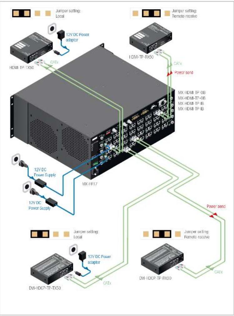
Remote powering
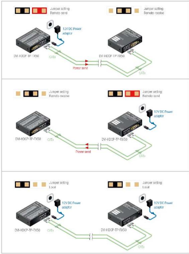
Please check the DC power settings in TP extenders before they are switched on. In the case of wrong jumper setting devices may be damaged? Power source can be set by jumper for local supply with plug-in adapter, or for remote supply through TP CATx cable. The extenders are able to receive and/or send power.

When the remote power feature is used, check the settings both ends of the TP line.
▲ Never send power towards Lightning Matrix IO cards from TP extender units.
12V DC POWER ADAPTOR is the default setting of the jumper. If no jumper is placed on the pins, the extender cannot be powered on.
Jumper configurations
| Setting on the RX | Setting on the TX / Output Board |
| only local adaptor | only local adaptor |
| local adaptor + remote send | only remote receive from RX |
| only remote receive from TX | local adaptor + remote send |
| only local adaptor | PWR → 12V DC not connected to OB |
| only remote receive from CB | PWR → 12V DC connected to OB |
Further information
The Product brief and further information is available at www.lightware.eu.
See the Downloads section on the website of the product
Contact us
sales@lightcare.e
+38 1255 3800
support@lightware.eu
+38 1 255 38
Lightware Visual Engineering LLC.
Pekrdy 15, Budapest H-1071, Hungary
Oct. ver: 2.0
17201015
Remote power options
flowchart
graph TD
    A["12V DC Power adapter"] --> B["DTI-HDCP-TP-TX50"]
    B --> C["CATx"]
    C --> D["Power send"]
    D --> E["DTI-HDCP-TP-RX50"]
    E --> F["CATx"]
    F --> G["DTI-HDCP-TP-TX50"]
    G --> H["CATx"]
    H --> I["Power send"]
    I --> J["DTI-HDCP-TP-RX50"]
    J --> K["CATx"]
    K --> L["DTI-HDCP-TP-TX50"]
    L --> M["CATx"]
    M --> N["Power send"]
    N --> O["DTI-HDCP-TP-RX50"]
    O --> P["CATx"]
    P --> Q["DTI-HDCP-TP-TX50"]
    Q --> R["CATx"]
    R --> S["Power send"]
    S --> T["DTI-HDCP-TP-RX50"]
    T --> U["CATx"]
    U --> V["DTI-HDCP-TP-TX50"]
    V --> W["CATx"]
    W --> X["Power send"]
    X --> Y["DTI-HDCP-TP-RX50"]
    Y --> Z["CATx"]
flowchart
graph TD
    A["12V DC Power adapter"] --> B["HDMI-TP-TX50"]
    A --> C["12V DC Power Supply"]
    A --> D["DVI-HDCP-TP-TX50"]
    E["MDMI-TP-RX50"] --> F["Power send"]
    G["MX-HDMI TP OB"] --> H["Power send"]
    I["MX-HDMI TP-OB"] --> H
    J["MX-HDMI TP IB"] --> H
    K["MX-HDMI TP-IB"] --> H
    L["Jumper setting: Local"] --> M["12V DC Power adapter"]
    N["Jumper setting: Remote receive"] --> O["12V DC Power Supply"]
    P["Jumper setting: Local"] --> Q["12V DC Power adapter"]
    R["Jumper setting: Remote receive"] --> S["12V DC Power adapter"]
    T["Jumper setting: Local"] --> U["12V DC Power adapter"]
    V["Jumper setting: Remote receive"] --> W["12V DC Power adapter"]