DVI-HDCP-TPS-TX95 - Audio-/Videoverlängerung Lightware - Kostenlose Bedienungsanleitung
Finden Sie kostenlos die Bedienungsanleitung des Geräts DVI-HDCP-TPS-TX95 Lightware als PDF.


Benutzerfragen zu DVI-HDCP-TPS-TX95 Lightware
0 Frage zu diesem Gerät. Beantworten Sie die, die Sie kennen, oder stellen Sie Ihre eigene.
Eine neue Frage zu diesem Gerät stellen
Laden Sie die Anleitung für Ihr Audio-/Videoverlängerung kostenlos im PDF-Format! Finden Sie Ihr Handbuch DVI-HDCP-TPS-TX95 - Lightware und nehmen Sie Ihr elektronisches Gerät wieder in die Hand. Auf dieser Seite sind alle Dokumente veröffentlicht, die für die Verwendung Ihres Geräts notwendig sind. DVI-HDCP-TPS-TX95 von der Marke Lightware.
BEDIENUNGSANLEITUNG DVI-HDCP-TPS-TX95 Lightware
LIGHTWARE
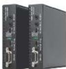
Quick Start Guide
HDMI-TPS-TX95
HDMI-TPS-RX95
DVI-HDCP-TPS-TX95
DVI-HDCP-TPS-RX95
Important Safety Instructions
Please read the supplied safety instruction document before using the product and keep it available for future reference.
Introduction
The HDMI-TPS-RX/TX95 and DVI-HDCP-TPS-RX/TX95 are DVI 1.0 and HDMI 1.4 compatible long-distance extenders. The difference between HDMI and DVI-HDCP models is just the HDMI and DVI connector. The units offer bi-directional RS-232, Infra-Red (IR), and Ethernet signal pass-through on the same CATSe...CAT7 cable that carries the uncompressed HDMI video and audio signal.
Box Contents



Infrared writer unit
[for TX95]

Infrared detector unit
(for RX95)
Remote Power Options
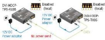
The TPS extenders can be powered remotely by its extender pair or a TPS matrix board. This feature can be enabled or disabled with jumper settings. Switch off the extenders. Loose the screws and remove the small plate from the right side of the enclosure. To enable the remote power function place the jumper block once all the pinheads. To disable it places the jumper block onto the upper line pinheads only. In case of enabled remote power on both extenders the local extender can be placed at any side.
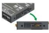
| TX side | RX side | |
| Enabled | ||
| Disabled (default) |
The TPS remote powering must be used only with 95 series TPS extenders and MX TPS matrix boards. Using it with other devices may damage both units. Connecting incompatible devices with similar connectors may cause harm to the devices. Never connect any third party device to the extender with remote powering!
① AWG 26 cables are not recommended with remote powering (reduce cable distances).
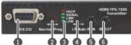
Front View
Rear View
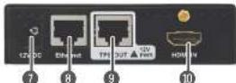
① The transmitters and the receivers have the same construction and connectors.
The product is compatible with

HDBaseT™ and the HDBaseT Alliance logo are trademarks of the HDBaseT Alliance.
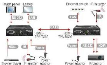
Connecting Steps
flowchart
graph TD
    A["Touch panel"] -->|RS-232| B["Laptop"]
    B -->|LAN| C["Internet"]
    C -->|CATx| D["Ethernet switch"]
    D -->|IR| E["IR detector"]
    C -->|HDMI-TPS-TX95| F["Power"]
    F --> G["Blu-ray player"]
    F --> H["Power adaptor"]
    H --> I["Power adaptor"]
    I --> J["Projector"]
    D --> K["Power"]
    K --> L["Power adaptor"]
    L --> M["Blu-ray player"]
    style A fill:#f9f,stroke:#333
    style B fill:#ccf,stroke:#333
    style C fill:#cfc,stroke:#333
    style D fill:#fcc,stroke:#333
    style E fill:#cff,stroke:#333
    style F fill:#ffc,stroke:#333
    style G fill:#cfc,stroke:#333
    style H fill:#cfc,stroke:#333
    style I fill:#cfc,stroke:#333
    style J fill:#cfc,stroke:#333

Connect the TPS output port of the Transmitter to the TPS input port of the Receiver by a CATx cable.

Connect a source to the HDMI (DVI-D) input port of the transmitter.

Connect an IR emitter unit to the IR output part of the transmitter.

Connect a controller device to the local RS-232 port of the transmitter. Make sure the RS-232 switch is in Normal position.

Optionally connect a laptop to the Ethernet port of the transmitter

Connect a sink device to the HDMI (DVI-D) output port of the receiver.

Connect a serial cable between the sink device and the RS-232 port of the receiver.

Connect the receiver to Ethernet by a QATx cable.

Connect an IR detector unit to the IR input port of the receiver.

Firstly correct the power adaptor to the DC input of the power injector, then secondly to the AC power socket.
Locking DC Plug
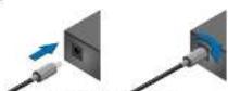
Twist 90° clockwise to lock.
Front and Rear View - Legend
1 RS-232 port Local RS-232 port for bidirectional serial data connection and performing firmware upgrade (programming).
2 RS-232 switch Normal: serial data is passed through the device. Prog: RS-232 pass-through function is disabled, the device is ready for the firmware upgrade.
3 Status LEDs See the next section.
4 TPS mode LR: Long reach TPS mode; lower resolution (max 1060p), switch longer distances. Auto: TPS mode is determined automatically.
5 IR input IR signal input connector (for 3.5 mm Jack, 3-pole, TRS plug).
6 IR output IR signal output connector (for 3.5 mm Jack, 2-pole, TS plug)
7 DC input 12V DC input for local power supply.
8 Ethernet port The Ethernet data is passed through the device.
9 TPS port TPS port to the other compatible device (extender / matrix / brand).
10 HDMI port Video port for DVI or HDMI signal.
Mounting Options
Lightware offers three types of mounting accessory to fix the extension: Under Desk Mounting Kit (UD-kit)
The UD-Kit makes easy to mount one extender under any flat surface (e.g. furniture)
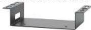
UD Mounting Kit Double (UD-kit double)
The UD-kl double makes easy to mount two extenders under any flat surface (e.g. fumbrue)
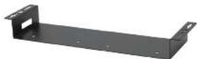
Rack Shell
10 high rack shelf provides mounting holes for fastening up to four extenders.

Mounting Steps
Always use the fixing screws which are supplied with the mounting accessory. If you insert screws longer than 8 mm, the device can be damaged.
1 Unplug all the cables connected to the device(s).
2. Turn the device(s) upside down.
3. Put the shelf upside down on the device(s). Position it to get the mounting holes aligned
4. Easten the device on the shelf with the provided screws
5. Fix the shelf to the desired place (screws are not supplied).
Status LEDs
HDCP
CFF: video output signal is not encrypted with HDCP.
ON: when output signal is encrypted with HDCP.
VIDEO
- OFF: no video signal transmission.
CN: video signal transmission
LINK
OFF: TPS connection failed between the devices.
- BLINKING: TPS connection is detected and LPPF link mode is active - ON: TPS connection is detected and HDBT or LR link mode is active.
LIVE
OFF: no power supply or cut of order.
BUNKING device is powered and ready to use
TPS link modes
If an extender and a TPS matrix board are paired the board forces the extender to use the settings of the matrix. The extender's TPS mode switch has no effect. For detailed information about the TPS link modes in case of matrix boards see the user's manual of the matrix.
Installation of the Extender with a Matrix
- Power off all devices. (Installing with powered devices may harm them.)
- Check the RS-232 switches on the extended(s); they must be in Normal position.
- The state of the IPS Ink mode switch makes no difference of the extender because the connected board forces the extender to use the settings of the matrix.
- Set the remote power mode of the matrix boards with the jumpers on them. Every port can be set for remote powering separately. To enable the remote power function place the jumper block onto all the pinheads of the desired port. To disable it remove the jumper block. For detailed information, see the user's manual of the matrix.
- Set the extended's remote power mode with the same method as it mentioned in the standalone case.
- Pair the extended(s) and the matrix board(s) with CATx cable(s). The transmitters' TPS OUT with the input boards' TPS IV and the receivers' TPS IV with the output boards' TPS OUT.
- Connect the video source(s), sink(s) and the desired accessory device(s) to the matrix (MX-IPS boards don't support the IR pass-through).
- Connect the video source(s), sink(s) and the desired accessory device(s) to the extensions.
- Supply that matrix boards with 12V 6,67A DC which have ports with enabled remote powering.
- Supply the extenders with 12V 2A DC. If the remote power is disabled on the connected matrix card's port, local adaptor must be used for the extender.
- Connect the power cord of the matrix into the outlet and switch on the matrix.
- Supply the other connected units.
Further Information
The Product brief of this appliance and further information is available at www.lightware.com. See the Downloads section on the dedicated product page.
Contact Us
sales@lightware.com
+36 1 255 3800
support@geware.com
+38 1 255 3010
Lightware Visual Engineering LLC.
Petardy 15, Budapest H-1071, Hungary
Oct. 19:21
1920:112
TPS Link Modes
The TPS working mode between the transmitter and the receiver parties is determined by the mode set in them. Both parties influence on the setting which determines the final TPS transmission mode. The following TPS modes are defined:
- Long reach (LR): Longer CATx cable length, less bandwidth (limited resolution). The LPPF mode is not available in LR TPS link mode.
- HDBaseT™(HDBT): more bandwidth (higher resolutions), shorter CATx cable length. If no video present, the units change to LPPF mode automatically.
- Low Power Partial Functionality (LPPF): Only Ethernet, RS-232 and IR are extended.
Toggling Between TPS Link Modes
The toggle switch on the scenders can be used to toggle between the LR and Auto TPS modes. If both units have Auto state and there is valid video signal on the transmitter the common mode will be HDBT. If the video signal disappears devices go into LPPF mode.
| HDCP |
| SIGNAL |
| LINK |
| LIVE |
| LR Auto IR IN |
TPS mode between an extender and a port of a matrix board
If an extender and a TPS matrix board are paired the board forces the extender to use the settings of the matrix. The extender's TPS mode switch has no effect.
① Always use the Auto mode will third-party devices!
| The negotiatedTPS working mode | Selected mode (RX) | ||
| LR | Auto | ||
| Selectedmode(TX) | LR | LR | LR |
| Auto | LR | HDBT | |
Maximum Extension Distances
| Resolution | Pixel clock rate | Cable lengths(Auto / Long reach TPS mode) | ||
| CAT5aANG24 | CAT7ANG28** | CAT7ANG23 | ||
| 1024s/96s/60Hz | 65 MHz | 120 m / 120 m ^2 | 90 m / 120 m ^2 | 120 m / 120 m ^2 |
| 1230s/72s/60Hz | 73.6 MHz | 120 m / 120 m ^2 | 90 m / 120 m ^2 | 120 m / 120 m ^2 |
| 1920s/165s/60Hz (26bps) | 145.5 MHz | 120 m / 120 m ^2 | 90 m / 120 m ^2 | 120 m / 120 m ^2 |
| 1920s/120s/60Hz | 162.5 MHz | 100 m / NA | 90 m / NA | 120 m / NA |
| 1900s/120s/60Hz | 182 MHz | 100 m / NA | 90 m / NA | 120 m / NA |
| 1920s/105s/60Hz (86bps) | 220 MHz | 70 m / NA | 70 m / NA | 120 m / NA |
| 580s/27s/60Hz UHD | 297 MHz | 70 m / NA | 70 m / NA | 120 m / NA |
| 410s/27s/60Hz UH | 397 MHz | 70 m / NA | 70 m / NA | 120 m / NA |
* Long reach TPS mode supports pixel clock frequencies up to 248.5 MHz.
** AWG 26 cables are not recommended with remote powering.
Above values are valid when the transmitter is powered by a local adaptor; distances may decrease depending on the powering mode (local or remote) and cable quality. To specify the accurate extension distances, please also check the documentation of the connected HDBaseT-compatible device.
① CATT SFTP AWG23 cable is always recommended.
Remote Power Options
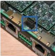
The TPS extender can be powered remotely by the connected TPS matrix board or its extender pair. This feature can be enabled or disabled with jumper settings for every part separately. Switch off the matrix. Remove the desired cards. Pinheads are behind of the TPS connectors. To enable the remote powering function of the port place the jumper block onto all the corresponding pinheads. Connect the external 12V DC 6,57A power adaptor to the card separately. Finally, set the extenders' desired power modes. To disable the remote powering function for a port remove the jumper block from the corresponding pinheads.
Jumper Settings
Place the jumper blocks onto all the pinheads of those units which you want to be powered remotely. For disabling the remote powering remove the jumper blocks and place them onto the upper line pinheads only.
Read carefully all the detailed instructions about remote powering devices! Never use remote powering with third-party units!
① AWG 26 cables are not recommended for remote powering (reduce cable distances).
For more information please download the User's Manual of the MX-FR motor switches.
Standalone with Local Powering
text_image
DVI-HDCP- TPS-TX95 12V DC Power adaptor Disabled (local) 12V DC Power adaptor No power send CATs DVI-HDCP- TPS-TX95 Disabled (local)Standalone with Remote Powering for RX
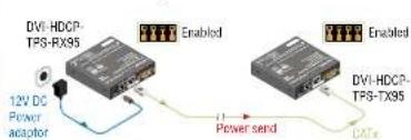
text_image
DVI-HDCP- TPS-RX95 12V DC Power anaptor Enabled DVI-HDCP- TPS-TX95 Enabled DVI-HDCP- TPS-TX95 Power send CATxBi-directional Pass-through Data Lines
The direction of the video extension is fixed from TX towards RX but the pass-through data lines are bi-directional. It means the RS-232, IR, Ethernet source and sink devices can be connected either to the TX or the RX.
Ethernet
The Ethernet port on the RX or on TX can be connected to a LAN hub, switch or router with a LAN cable. The other side believes as an Ethernet unlock port. Extenders support 10/100 MHz sec data transfer rate. The direct access is also supported with cross-link cable. The Ethernet port has auto crossover function, it is able to recognize and handle both cable types: patch and cross TP cables.
RS-232
Third party devices with standard RS-232 port are supported as the extenders work in pass-through mode. TX and RX provide RS-pole O-aut female connector. Use straight-serial cable to connect a DTE device to an extender and use a cross serial cable in case of pairing a DOE device to the other TFS extender. The RS-232 options – the baud rate and the party bits are set on the third party devices and it can be anything. The extenders support any kind of serial settings.
① Please read the user's manual of the RS-232 device to get its type. The extenders work as DCE devices.
Typical Application
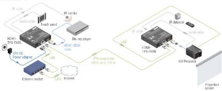
flowchart
graph TD
    A["IR cable"] --> B["Serial cable"]
    B --> C["Touch panel"]
    C --> D["Blue-ray player"]
    D --> E["HDMI-HDMI cable"]
    E --> F["12V DC Power adaptor"]
    F --> G["Ethernet switch"]
    G --> H["LAN"]
    H --> I["Internet"]
    I --> J["TPS connection CATs up to 170 m"]
    K["IR detector"] --> L["HDMI-TPS-RK95"]
    L --> M["HD Projector"]
    M --> N["Projection screen"]
Standalone with Remote Powering for TX
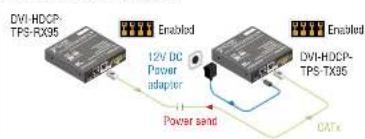
flowchart
graph TD
    A["12V DC Power adapter"] --> B["DVI-HDCP-TPS-RX95"]
    C["CAN Bus"] --> B
    B --> D["Enabled"]
    B --> E["Enabled"]
Infra-Red (IR)
One emitter and one detector is enough for remote controlling one IR sink device. If there is an IR sink device to be controlled next to the TX and the other one is next to the RX, two emitter-detector pairs are needed. The IR emitter and the detector have standard 3.5 mm TRS (jack) connectors. The emitter's plug has two poles (mono) and the detector's plug has three poles (silver).
| 123Detector - 3-pole-TRS Emitter - 2-pole-TS | 12-3 | ||
| 1 Tip Signal (active low) ≥ Tip +5V | |||
| 2 Ring GND 2 Ring | Signal (active low) | ||
| 3 Sleeve +5V / Sleeve | |||
① The second emitter and detector pair can be ordered from Lightware separately.
① IR extension is available only with point-to-point connection of the extensions.
Specification
General
| Compliance | CE |
| ENI / EMC | EN 56035:2017 / EN 55032:2015 |
| Coding | passive |
| Exclasure | 1 mm slee |
| Dimensions | 100.4 W x 100x4 D x 28 Hmm |
| Weight (TX) | 300 g (HDMI) / 310 g (DV/HDCP) |
| Weight (RX) | 320 g (HDMI) / 330 g (DV/HDCP) |
Digital Video Signal
| Supported signals | DVI 1.0, HDMI 1.4 |
| Signal standard | DVI and HDMI standard which supports embedded audio |
| Supported resolutions | 1920x1089@120 Hz, 24 bit |
| up to 4K/UHD (30Hz RGB 4A/4, 60Hz YChCr 4N20) | |
| 3D support | yes |
| HDCP complaint | yes |
| CEC support * | transparent |
| EIDD support | transparent |
*Only between HDMI-TPS-TX95 and HDMI-TPS-RX95 models.
| Cable length (HDMI/DMI input port) | max. 20 m |
| Equalization | adaptive, automatic |
Power
| Power supply | external power adaptor / remote power via TPS |
| Power adaptor | Input 100-240 V AC 50/60 Hz, Output 12V DC. 2.5A |
| Power consumption (TX) | 3.6W (typ) / 4.2W (max) |
| Power consumption (RX) | 5.3W (typ) / 6.1W (max) |
Connectors
| TX input, RX output | HWI / DVH connector |
| TX output, RX input | RJAS (TPS interface) |
| Ethernet | RJAS |
| IR input, output | 3.5 mm (2.8") ack connector |
| Serial port | 9-pole D-sub |
| Power | lacking DC connector (2.1 / 5.5 mm) |
TPS port (HDBaseT™-compatible)
| Ethernet pass-through | YES |
| RS-232 pass-through | YES |
| IR pass-through | YES |
Integrated with Local Powering
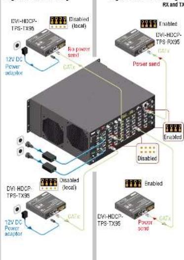
flowchart
graph TD
    A["12V DC Power adaptor"] --> B["DVI-HDCP-TPS-TX35"]
    B --> C["Disabled (local)"]
    B --> D["Disabled (local)"]
    B --> E["12V DC Power adaptor"]
    B --> F["No power send"]
    B --> G["CATx"]
    H["RX and TX"] --> I["Enabled"]
    I --> J["DVI-HDCP-TPS-TX35"]
    J --> K["Disabled"]
    J --> L["Disabled"]
    J --> M["12V DC Power adaptor"]
    J --> N["CATx"]
    O["Power send"] --> P["DVI-HDCP-TPS-TX35"]
    P --> Q["Disabled"]
    P --> R["Disabled"]
    P --> S["12V DC Power adaptor"]