WP-UMX-TPS-TX120-US - Audio-/Videoverlängerung Lightware - Kostenlose Bedienungsanleitung
Finden Sie kostenlos die Bedienungsanleitung des Geräts WP-UMX-TPS-TX120-US Lightware als PDF.


Benutzerfragen zu WP-UMX-TPS-TX120-US Lightware
0 Frage zu diesem Gerät. Beantworten Sie die, die Sie kennen, oder stellen Sie Ihre eigene.
Eine neue Frage zu diesem Gerät stellen
Laden Sie die Anleitung für Ihr Audio-/Videoverlängerung kostenlos im PDF-Format! Finden Sie Ihr Handbuch WP-UMX-TPS-TX120-US - Lightware und nehmen Sie Ihr elektronisches Gerät wieder in die Hand. Auf dieser Seite sind alle Dokumente veröffentlicht, die für die Verwendung Ihres Geräts notwendig sind. WP-UMX-TPS-TX120-US von der Marke Lightware.
BEDIENUNGSANLEITUNG WP-UMX-TPS-TX120-US Lightware
LIGHTWARE
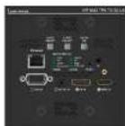
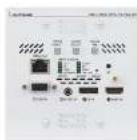
Quick Start Guide
WP-UMX-TPS-TX-120-US Black, White
WP-UMX-TPS-TX130-US Black, White
FP-UMX-TPS-TX130-MKM
Front View
text_image
Lanetwork WPU-002-THP-TX130-05 1 2 3 4 5 6 7 8 9 10 11 12 13 14 15 16 17 18 19 20 21 22 23 24 25 26 27 28 29 30 31 32 33 34 35 36 37 38 39 40 41 42 43 44 45 46 47 48 49 50 51 52 53 54 55 56 57 58 59 60 61 62 63 64 65 66 67 68 69 70 71 72 73 74 75 76 77 78 79 80The product is compatible with any HDBaseT ^™ third party devices.

HDDaseT ^™ and the HDDaseT Alliance logo are trademarks of the HDDaseT Alliance.
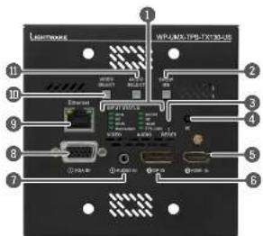
Front View Legend
Status LEDs The LEDs give feedback about the slate of the unit, the video and audio signals. See the attached list for details.
2 Show me Button Special functions are available with this button (e.g. enable DHCP/dynamic IP) or restore technology default settings).
3 Reset Button The same as disconnecting the device from the power source and reconnecting it again.
4 IR Detector IR Detector can sense IR light which can be forwarded to the receiver side or use for controlling functions.
5 HDMI Input input for a digital video source. Applied cable shall not be more, than 30 m (at 1080p) and 15 m (at 4K).
6 DisplayPort Input Input for digital video source (only on TX130 modes). Applied cable shall not be more, than 30 m (at 2.7 Gbps data speed).
7 Audio Input 3.5 mm Jack connector for unbalanced analog audio signal.
8 VGA Input Input for an analog video source. Using a VGA cable where all the pins are wired (DDC channel) is highly recommended.
9 Ethernet Locking RJ45 connector for Ethernet communication.
10 Video Select Manual switching between the video inputs.
Audio Select Manual switching between the audio inputs.
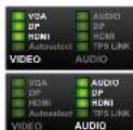
Front Panel LEDs
Video sources
■ OFF: video source is not selected.
- BLINKING: video source is selected but not active.
- ON: video source is selected and active.
Audio sources
- OFF: audio source is not selected
- BLINKING: audio source is selected but not active. - ON (with short pause): audio source is selected and
port is active but not embedded to the output video stream.
- ON: audio source is selected, the port is active and the audio is embedded in the video. - When Autoselect is enabled and video signal is not present at all, video LEDs drive.
Autoselect LED
- OFF: autoselect is disabled.
- BLINKING: autoselect is enabled; searching for signal (video LEDs also blink).
- ON: autoselect is enabled; active video signal is found ① A port is active if there is a valid signal on it.
TPS LINK
- OFF: no TPS link between transmitter and receiver - BLINKING (slow): low power mode is active.
- BLINKING (fast): E theme: fallback mode is active.
- ON: TPS link is established, HDBaseT or Long Reach mode is active
The Ground Truth image displays a single, solid horizontal line. According to Rule 2 (UNDERSCORE & LINE RULES), if the GT contains lines used for stylistic emphasis or as background elements (like ruled paper), the OCR result must ignore them. The provided OCR content is "____", which consists of four underscores. This is incorrect because underscores are not equivalent to a solid line and are not permitted under the “Stylistic/Background Lines (Ignore)” rule. The OCR has hallucinated underscores where none should exist in the GT, violating the “Stylistic/Background Lines (Ignore)” rule. Therefore, the OCR result is inconsistent with the Ground Truth.
bio is embedded in the video.
of an also LEDs.
m = 311
VGA AUDIO
DP DP
HD390
Autoport
AUDIO
VIDEO ADJING
广力云智慧零售收银系统
(1) 2017年1月1日
VGA AUDIO
DF
UP
UP
Autumnart TEG LINK
VIDEO AUDIO
VEGETS AGNOCY
cle is active
Important Safety Instructions
Please read the supplied safety instruction document before using the product and keep it available for future reference.
Introduction
Lightwave's W/FFP-UMX-TPS extenders transmit universal video at a resolution up to 4K, audio and control up to 170 m distance over a single QATx cable. The products have HDBase™ integration with additional Lightwave developments. This transmitter was designed for digital and analog video and audio signals e.g. CVL VGA, HDMI.4 and DP 1.1 with analog stereo audio from total inputs or embedded 7.1 HDR audio and to handle HCCP encryption.
Box Contents
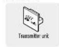


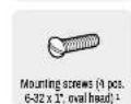
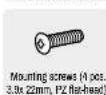
^1 For white models in WP-UMX-TPS-100 series. ^2 For black models in WP-UMX-TPS-100 series.
Rear View
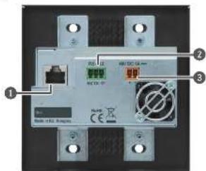
text_image
RE: 12 RE: 13 RE: 14 RE: 15 RE: 16 RE: 17 RE: 18 RE: 19 RE: 20 RE: 21 RE: 22 RE: 23 RE: 24 RE: 25 RE: 26 RE: 27 RE: 28 RE: 29 RE: 30 RE: 31 RE: 32 RE: 33 RE: 34 RE: 35 RE: 36 RE: 37 RE: 38 RE: 39 RE: 40 RE: 41 RE: 42 RE: 43 RE: 44 RE: 45 RE: 46 RE: 47 RE: 48 RE: 49 RE: 50 RE: 51 RE: 52 RE: 53 RE: 54 RE: 55 RE: 56 RE: 57 RE: 58 RE: 59 RE: 60 RE: 61 RE: 62 RE: 63 RE: 64 RE: 65 RE: 66 RE: 67 RE: 68 RE: 69 RE: 70 RE: 71 RE: 72 RE: 73 RE: 74 RE: 75 RE: 76 RE: 77 RE: 78 RE: 79 RE: 80 RE: 81 RE: 82 RE: 83 RE: 84 RE: 85 RE: 86 RE: 87 RE: 88 RE: 89 RE: 90 RE: 91 RE: 92 RE: 93 RE: 94 RE: 95 RE: 96 RE: 97 RE: 98 RE: 99 RE: 1001 TPS Output Port
Locking RJ45 connector for CAIX cables to a TPS receiver unit. Remote operating areas hangers through this connector
Z RS-232 Port 3-pole Phoenix connector for RS-232 serial port.
3 DC Input 48V DC input connector for local powering.
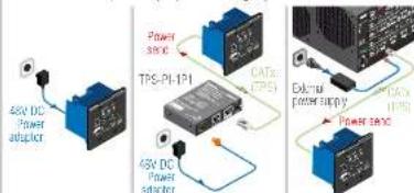
Power Supply Options
The transmitter can be powered by any of the following ways:
text_image
45V DC Power adapter TPS-PL-1P1 CATs (TPS) 45V DC Power adapter CATs (TPS) 45V DC Power adapter- Local adaptor 2. Remote power injector 3. Matrix board
⚠ Warranty void if damage occurs due to the usage of a different power source.
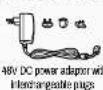
① Please note that the 45V power adaptor is an optional accessory which can be purchased separately:
TPS-TXRX00 and TPS-TXRX95 are not PoE-compatible, thus not able to remote power the WP-UMX-TPS-TX200 series and rice versa. WP-UMX-TPS-TX300 series contains PoE-compatible remote power function, RX85 and TX85 extenders can be remote powered only by each other.
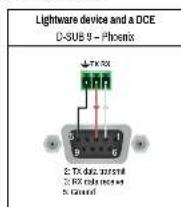
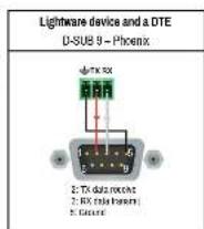
Viring Guide for RS-232 Data Transmission
The transmitters are built with 3-pole Phoenix connector. See the below examples of connecting to a DCE (Data Circuit-terminating Equipment) or a DTE (Data Terminal Equipment) type device:
Optional Accessories
The following accessories can be purchased separately:
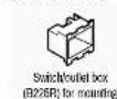
Compatible Devices
The transmitters are compatible with all Lightware TPS receivers, matrix boards and third-party devices based on HDBase-T™ technology.
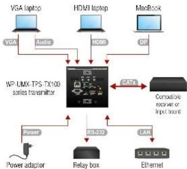
Connecting Steps
flowchart
graph TD
    A["VGALaptop"] -->|Audio| B["WP-UMX-TPS-TX100 series transmitter"]
    C["HDMI laptop"] -->|Audio| B
    D["MacBook"] -->|Audio| B
    B --> E["RS-232"]
    E --> F["Relay box"]
    F --> G["Power adaptor"]
    G --> H["Power"]
    H --> I["Ethernet"]
    B <-->|CATx| J["Compatible receiver or input board"]
    E <--> K["LAN"]
CATx Connect the transmitter and a compatible receiver or the matrix input board by a CATx cable via the TPS connectors.
VGA Connect the transmitter and the sources using the inputs and VGA / DVH / HDMI / DisplayPort cables.
Audio Optionally connect an asymmetric audio device with unbalanced audio signal (e.g. a VGA laptop) to the 2.5" TRS (jack) audio input port.
LAN Optionally connect the transmitter to a LAN network in order to control the device.
RS-232 Optionally connect a controller/controlled device (e.g. relay box) in the serial port.
Power See the Power Supply Options section.

Further Information
The document is valid with the following timeframe version: 1.2.0
The User's manual of this appliance is available on www.ightware.com.
See the Downloads section on the dedicated product page
Contact Us
sales@lightsure.com
+30 12553800
support@lightware.com
+36 1 255 3810
Lightware Visual Engineering LLC.
Pelordy 16, Budapest H-1071, Hungary
Oct. ver: 2.3
19200113
Front Panel Button Functions
Video Input Selection
The desired video input can be selected by pressing the Video select button on the front panel. The selection order of the inputs depend on the model as follows
• TX120 models: → VGA → HDMI → Autoselect
VGA DP HDMI AutoSelect
Audio Input Selection
The desired audio input can be selected by pressing the Audio select button on the front panel. The selection order of the inputs depend on the model.
① If 4K video is selected to the output, analog audio cannot be embedded to the video stream due to the limitations of the video IC, thus the original audio stream will be transmitted.
Cross Audio-embedding: The video and audio inputs can be combined with imitations. Below table contains the allowed connections:
| Audio source | ||||
| HDMI | DP | Audio | ||
| Video source | HDMI | √ | - | √ |
| DP | - | √ | √ | |
| VCA | - | - | √ | |


The video and audio inputs can be also selected by using LOC (Lightwave Device Controller), sending a proised command, or using AutoSelect. Lock / Unlock Buttons AUDIO SHOW
Press the Audio select and the Show me bellars together.
Sel a Dynamic IP Address
-
Keep the Show me button pressed for 5 seconds; all front panel LEDs start to hide
-
Release the button, then press it 3 times quickly. DHOP is now enabled.
Software Control - Using Lightware Device Controller (LDC)
The device can be controlled from a computer through the Ethernet port using Lightwave Device Controller. Please download the application from www.ighware.com, install on a Windows PC or a macOS and connect to the device via the Ethernet port. LDC software contains many useful built-in tools which can be used for signal analysis like the followings:
Mounting Options - WP-UMX-TPS Wall Plates
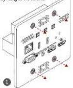
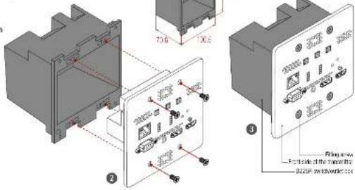
Thanks to the design of Lightware devices. WP-UNX-TPS wall plates transmitter can be mounted easily into an industrial standard box as the figures show below. B225R switch/outlet box is not supplied with the product, it can be purchased separately.
1 Release and remove the fixing screws from the front side of the extensor.
2 Insert the extender into the B225R cutter box and position it to get the holes aligned.
3 Fasten the front side of the extender to the B225ft outlet box by fitting all the screws.
text_image
Technical diagram showing assembly of electronic components with labeled parts and annotations in ChineseMounting Options - FP-UMX-TPS-TX130-MKM
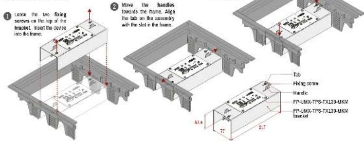
FP-UMX-TPS-TX130-MKM bracket is supplied with the product. It is compatible with the CRME265 floorbox type (MK CableInk Plus Modular series).
text_image
1. Loose the two fixing screws on the top of the bracket. Insert the device into the frame. 2. Move the handles towards the frame. Align the tab on the assembly with the slot in the frame. 3. Tab Fixing screw Handle FP-UMX-TPS-TX130-MKM FP-UMX-TPS-TX130-MKM bracket 63.4 77 2.7Maximum Extension Distances
Below values are valid when the transmitter is powered by a local adaptor; distances may decrease depending on the powering mode (local or remote) and cable quality.
| Resolution | Pixel clock rate | Cable height (Auto I Long reach TPS mode) | ||
| CAT50 ANG24 | CATT ANG26 | CATT ANG23 | ||
| 1025/208/04Hz | 85 MHz | 120 m / 120 m-7 | 95 m / 120 m-7 | 120 m / 120 m-7 |
| 1025/227/05/34Hz | 73.8 kHz | 120 m / 120 m-7 | 95 m / 120 m-7 | 120 m / 120 m-7 |
| 1025/230/06/34Hz (24bps) | 146.5 MHz | 120 m / 120 m-7 | 95 m / 120 m-7 | 120 m / 120 m-7 |
| 1025/230/06/34Hz | 152.8 MHz | 100 m / NA | 90 m / NA | 120 m / NA |
| 1025/230/06/34Hz | 182 MHz | 100 m / NA | 90 m / NA | 120 m / NA |
| 1025/230/06/34Hz (08bps) | 222.75 MHz | 70 m / NA | 70 m / NA | 120 m / NA |
| 208/221/03/34Hz UHD | 240 MHz | 70 m / NA | 70 m / NA | 100 m / NA |
| 208/221/03/34Hz 84 | 240 MHz | 70 m / NA | 70 m / NA | 100 m / NA |
* Long reach TPS mode supports pixel clock frequencies up to 148.5 MHz.
** If 4K video is selected to the output, analog audio cannot be embedded to the video stream due to the capabilities of the video IC, thus the original audio stream is transmitted.
To specify the accurate extension distances, please also check the documentation of the connected HDBaseT-compatible device.
① CAT7 SFTP AWG23 cable is always recommended.
Restore Factory Default Settings
- Keep the Show me button pressed for 10 seconds. After 5 seconds front panel LEDs
start to blink but keep the button pressed. The LEDs start to blink faster 5 seconds later. - Release the button, then press 1.3 times quickly; factory default settings are restored.
| IP Address (static) 120.168.0.100 | |
| Subnet Mask 255.255.255.0 | |
| Static Gateway 182.368.0.1 | |
| DHCP Disacled | |
| TCP/IP Port No. | LW2: 10001; LW3: 8007 |
| Selected Output port | Video: VGA; Audio Analog Audio input |
| Autoselect Disacled | |
| Output TPS Mode Auto | |
| Emulated EDID VGA port: F80; DP, HDMI ports: Dynamic | |
| RS-232 Mode Pass through | |
| RS-232 Control Protocol | LW2 |
| RS-232 Port Setting | 5780C B4UD, 8, N, 1 |
| RS-232 Command Injection Port No. | Local: 9001; TPS: 8002 |
| IR Command injection Port No. (local) | Input: 9001; Output: 9002 |
| IR Command injection Port No. (TPS) | Input: 9003; Output: 9004 |
Port Diagram (of TX130 models)
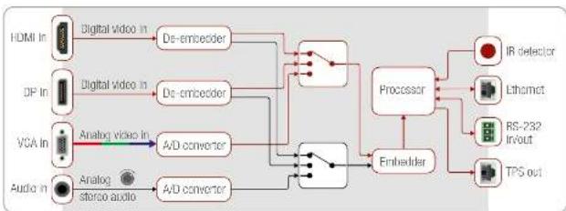
flowchart
graph LR
    A["HDMI In"] --> B["Digital video in"]
    C["DP In"] --> D["Digital video in"]
    E["VGA In"] --> F["Analog video in"]
    G["Audio in"] --> H["Analog stereo audio"]
    B --> I["De-embedder"]
    D --> J["De-embedder"]
    F --> K["A/D converter"]
    H --> L["A/D converter"]
    I --> M["Processor"]
    J --> M
    K --> M
    L --> M
    M --> N["IR detector"]
    M --> O["Lethamct"]
    M --> P["RS-232 Invoit"]
    M --> Q["TPS out"]
Typical Application
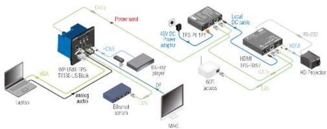
flowchart
graph TD
    A["Power send"] --> B["42V DC Power adapter"]
    B --> C["TFS-PI 1+1"]
    C --> D["Local DC cable"]
    D --> E["HDMI TFS-TX87"]
    E --> F["HDMI"]
    F --> G["HD Projector"]
    H["Analog audio"] --> I["WiFi access"]
    I --> J["LAN"]
    J --> K["Mac"]
    L["Bluetooth switch"] --> M["Diode"]
    N["MDA"] --> O["Analog audio"]
    P["Laptop"] --> Q["Analog audio"]
    R["Local DC cable"] --> S["Local DC cable"]
    T["HDMI"] --> U["Local DC cable"]