
KX-P1082 - Drucker PANASONIC - Kostenlose Bedienungsanleitung
Finden Sie kostenlos die Bedienungsanleitung des Geräts KX-P1082 PANASONIC als PDF.

| Produkttyp | Nadelmatrix-Drucker (Impact Dot Matrix) |
| Modell | Panasonic KX-P1082 |
| Abmessungen (B×T×H) | 403 × 286 × 115 mm |
| Gewicht | ca. 6,9 kg |
| Stromversorgung | AC 240 V, 50 Hz, 0,6 A |
| Druckgeschwindigkeit (Entwurf) | 160 Zeichen pro Sekunde |
| Druckgeschwindigkeit (NLQ) | 32 Zeichen pro Sekunde |
| Druckmodi | Entwurf, Courier NLQ, Bold PS NLQ, Komprimiert |
| Zeichen pro Zoll | 10 (Pica), 12 (Elite), 15 (halbkomprimiert), 17 (komprimiert), Proportionalabstand |
| Papierführung | Reibungs- und Traktorantrieb |
| Papierformat (Einzelblatt) | Breite: 102–229 mm, Höhe: 127–363 mm |
| Papierformat (Endlospapier) | Breite: 76–254 mm |
| Durchschlagskapazität | max. 3 Blatt (Gesamtdicke < 0,25 mm) |
| Lebensdauer Druckkopf | 100 Millionen Zeichen (Entwurfsmodus) |
| Farbband | Spezial-Kassette, nahtlos, schwarz, Lebensdauer ca. 3 Millionen Zeichen |
| Puffergröße | 1 KB |
| Schnittstelle | Parallel (Centronics); optional RS-232C seriell (XON/XOFF, ETX/ACK, DTR) |
| DIP-Schalter | 8 Schalter für Druckermodus, Zeichensatz, Papierauslauf, automatischen Zeilenvorschub u. a. |
| Selbsttest | Über LF-Taste beim Einschalten; DIP-Liste über FF-Taste |
| Betriebsumgebung | Temperatur: 5–40 °C, Luftfeuchtigkeit: 20–80 % |
Häufig gestellte Fragen - KX-P1082 PANASONIC
Benutzerfragen zu KX-P1082 PANASONIC
0 Frage zu diesem Gerät. Beantworten Sie die, die Sie kennen, oder stellen Sie Ihre eigene.
Eine neue Frage zu diesem Gerät stellen
Laden Sie die Anleitung für Ihr Drucker kostenlos im PDF-Format! Finden Sie Ihr Handbuch KX-P1082 - PANASONIC und nehmen Sie Ihr elektronisches Gerät wieder in die Hand. Auf dieser Seite sind alle Dokumente veröffentlicht, die für die Verwendung Ihres Geräts notwendig sind. KX-P1082 von der Marke PANASONIC.
BEDIENUNGSANLEITUNG KX-P1082 PANASONIC
WARNING:
TO PREVENT FIRE OR SHOCK HAZARD, DO NOT EXPOSE THIS PRODUCT TO RAIN OR ANY TYPE OF MOISTURE.
The serial number of the unit may be found on the label on the bottom of the unit. For your convenience, note this number below, and retain this book, along with your proof of purchase, to serve as a permanent record of your purchase in the event of a theft, or for future reference.
MODEL NO. KX-P1082
NAME OF DEALER ____
SERIAL NO. ____
DATE OF PURCHASE ____
IMPORTANT
The wires in this mains lead are coloured in accordance with the following code:
Green and yellow: Earth
Blue: Neutral
Brown: Live
As the colours of the wires in the mains lead of this apparatus may not correspond with the coloured markings identifying the terminals in your plug, proceed as follows:
The wire which is coloured green and yellow must be connected to the terminal in the plug which is marked by the letter E or by the safety earth symbol 12 or coloured green or green-and-yellow.
The wire which is coloured blue must be connected to the terminal which is marked with the letter N or coloured black.
The wire which is coloured brown must be connected to the terminal which is marked with the letter L or coloured red.
WARNING: This apparatus must be earthed.
●This equipment is produced to BS800:1977.
Operating Instructions
Impact Dot Matrix Printer
Panasonic
Before operating this unit, please read these instructions completely.
TABLE OF CONTENTS
Section
Page
INTRODUCTION
1.1 Product Overview 1-1
1.2 Names of the Parts 1-2
1.3 Specifications 1-3
INSTALLATION
2.1 Unpacking and Inspection 2-1
2.2 Site Requirements 2-1
2.3 Initial Setup 2-1
OPERATION
3.1 Switches and Indicators 3-1
3.2 Detectors 3-2
3.3 DIP Switches 3-2
3.4 Initialization 3-4
3.5 Self Test 3-5
3.6 Hex. Dump 3-5
3.7 Receive Buffer 3-5
3.8 Replacing the Covers 3-5
SOFTWARE COMMANDS
4.1 Introduction 4-1
4.2 Control Codes 4-1
4.3 Entering Control Codes Through Commercial Software Packages 4-1
4.4 Entering Control Codes Directly from the Keyboard 4-2
4.5 Entering Control Codes from Within a Program 4-2
4.6 Entering Hexadecimal Code 4-2
4.7 Control Codes 4-3
4.8 Mixing Print Modes 4-94
4.9 DIP Switches and Control Codes 4-96
INTERFACING
5.1 Parallel Interfacing 5-1
5.2 Connector Pin Signals 5-2
MAINTENANCE
6.1 Preventive Maintenance 6-1
6.2 Periodic Maintenance 6-1
6.3 Troubleshooting 6-2
APPENDIX A Character Set Tables A-1
APPENDIX B Proportional Spacing Tables B-1
APPENDIX C DIP Switch Settings...... C-1
APPENDIX D Download Character Matrix Blanks D-1
APPENDIX E Software Commands E-1
APPENDIX F Paper and Printing Area F-1
INDEX ……INDEX-1
Table
Page
INSTALLATION
2.1 Installation Requirements 2-1
OPERATION
3.1 DIP Switch Settings 3-3
3.2 International Character Set 3-3
3.3 IBM Proprinter Mode 3-3
SOFTWARE COMMANDS
4.1 Input Formats 4-3
4.2 Proportional Spacing: Standard Mode Characters 4-16
4.3 Print Mode Selection 4-21
4.4 International Character Set Locations 4-32
4.5 International Italic Character Locations 4-33
4.6 Dot Resolution 4-36
4.7 Dot Density (Dots per inch) 4-44
4.8 Selection of Paper Feed Amount 4-47
4.9 Mixed Print Modes (Standard Mode)... Control Codes Only 4-94
4.10 Mixed Print Modes (Standard Mode)... Selector Switch/Control Codes 4-94
4.11 Mixed Print Modes (IBM Proprinter Mode)... Control Codes Only 4-95
4.12 Mixed Print Modes (IBM Proprinter Mode)... Selector Switch/Control Codes 4-95
4.13 Software Control of DIP Switch Function 4-96
INTERFACING
5.1 Printer Status Signals 5-1
5.2 Connector Pin Configuration 5-1
MAINTENANCE
6.1 Troubleshooting 6-2
Figure
Page
INTRODUCTION
1.1 Parts Location 1-2
INSTALLATION
2.1 Removing the Printer Cover 2-1
2.2 Removing the Carriage stoppers 2-1
2.3A Positioning the Print Head 2-2
2.3B Removing the Ribbon Slack 2-2
2.3C Installing the Ribbon Cassette 2-2
2.4A Paper Separators 2-2
2.4B Installing the Paper Separators 2-2
2.5A Paper Feed Selector 2-3
2.5B Inserting a Single Sheet 2-3
2.5C Aligning a Single Sheet 2-3
2.6A Unlocking the Tractor 2-4
2.6B Raising the Tractor Cover 2-4
2.6C Inserting Fanfold Paper 2-4
2.6D Mounting the Paper 2-4
2.7 Stacking the Paper 2-5
2.8 Setting the Top of Form 2-5
2.9 Adjusting the Print Head Gap 2-5
OPERATION
3.1 ON LINE & OFF LINE 3-1
3.2 Location of DIP Switches 3-2
3.3 Replacing the Front Cover 3-5
3.4 Replacing the Top Cover 3-5
INTERFACING
5.1 Parallel Interface Connector 5-1
5.2 Timing Diagram 5-3
1.1 Product Overview
This printer is a durable, highly reliable dot matrix printer. In addition, it has a small footprint, making it ideal for a compact workstation.
This printer uses a nine pin print head to form a 9×9 dot matrix character in draft mode. In near letter quality mode, the matrix is 18×18. The standard character set consists of 96 ASCII characters which can be printed in the conventional font or in italics. DIP switches allow the user to select alternate IBM® character sets. With these sets, line graphics are available. The user can also select 10 international character sets.
In addition to Pica (10 characters per inch) and Elite (12 characters per inch) printing, this printer can print in compressed mode of 17 characters per inch and semi-compressed mode of 15 characters per inch. Compressed mode yields a total of 137 characters per line.
In addition to the four print pitches mentioned above, this printer has proportional spacing thus, five basic printing pitches are available.
The normal printing speed is 160 characters per second (CPS). Processing speed is increased by Bi-directional printing. That is, the printer prints right-to-left as well as in the normal left-to-right manner. A logic seeking technique is also used, giving the printer a look-ahead capability which allows it to skip blank spaces at the beginning and end of a line and the blank lines between paragraphs.
A wide variety of printing styles allows the user to create unique documents and drawings. You can print characters in double width or compressed, emphasized or underlined and print super or subscripts, etc. Using Bit-mapped graphics, the printer can produce special effects ranging from company logos to photo-like images.
The printer has friction and tractor feed capabilities as standard features and handles single sheet as well as fanfold paper. This enables the user to create letters on company letterhead or print reports from the computer. The seamless ribbon can print up to three million characters and the cassette design makes changing the ribbon quick, easy and clean.
A 1024 byte buffer (1K) is provided with the standard parallel interface. Serial communications is possible through an optional RS-232C interface board which supports XON/XOFF, ETX/ACK, and DTR drop handshaking protocols.
Some software for your Computer requires you to select a specific printer for the output.
You should select Panasonic if it is listed. If Panasonic is not listed in the software, you may select one of the following:
- Epson RX-80™...(DIP switch 1=ON)
- IBM Proprinter*...(DIP switch 1=OFF)
Please check your DIP switches after making selection. Refer to Section 3.3.
*See Appendix—for applicable code
1.2 Names of the Parts
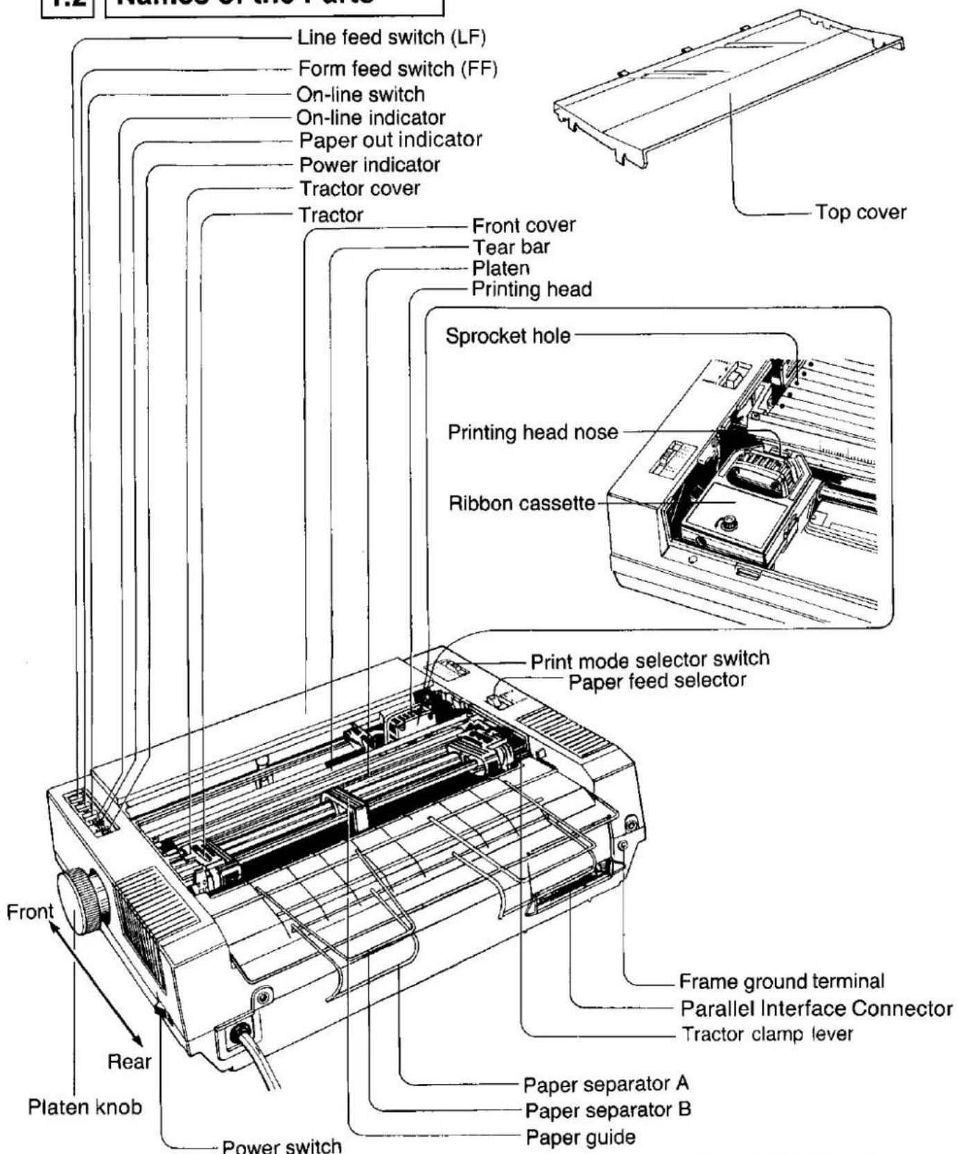
Figure 1.1 Parts Location
1.3 Specifications
| Power requirements: | AC 240 V (50 Hz) | ||
| Current: | 0.6 A | ||
| Fuses: | 1.25 A 250 V 2.5 A 250 V | ||
| Printing mode: | Draft, Near Letter Quality (Courier, Bold PS), Dot Graphics | ||
| Character set: | 96 ASCII characters, 96 Italic ASCII characters, 32 International characters (10 countries), 32 Italic International characters (10 countries), 135 IBM special characters | ||
| Dot configuration: | 3/254 inch (0.3 mm) dot diameter | ||
| Draft (Pica) | NLQ | ||
| Dot alignment(Hor.×Ver.) | 9×9 | 18×18 | |
| Dot pitch (Hor.) | 1120'' (0.21 mm) | 1240'' (0.11 mm) | |
| (Ver.) | 112'' (0.35 mm) | 1144'' (0.18 mm) | |
| Character size | |||
| Ordinary characters: | 0.078 (W)×0.095 (H) in. (1.99×2.42 mm) | ||
| Superscript/subscript characters: | 0.078 (W)×0.053 (H) in. (1.99×1.36 mm) | ||
| Number of characters per line(per inch (25.4mm)): | Pica | 80 CPL (10 cpi) | |
| Elite | 96 CPL (12 cpi) | ||
| Semi Compressed | 120 CPL (15 cpi) | ||
| Compressed | 137 CPL (17 cpi) | ||
| Pica elongated | 40 CPL (5 cpi) | ||
| Elite elongated | 48 CPL (6 cpi) | ||
| Semi Compressed elongated | 60 CPL (7.5 cpi) | ||
| Compressed elongated | 68 CPL (8.5 cpi) | ||
| Printing speed: | Draft-Pica 160 CPS | ||
| Draft-Elite 160 CPS | |||
| NLQ 32 CPS | |||
| Printing direction: | Text printing (Draft., NLQ): Bi-direction | ||
| Bit Image printing: Single-direction (left→right) | |||
| New line time: | Approx. 100 msec [with 1/6 inch (4.2 mm) line feeding] | ||
| Paper feed: | Tractor feed (with fanfold paper) | ||
| Friction feed (with single sheet) | |||
| Paper used: | Fanfold (continuous) paper width: 3~10 inches (76~254 mm) | ||
| Single sheet Width: 4~9 inches (102~229 mm) | |||
| Height: 5~14.3 inches (127~363 mm) | |||
| Thickness (paper weight in pound): 11~21.5 pound | |||
| (paper weight in g/m2): 41~81 g/m2 (only 1 sheet) | |||
| 3 max. | |||
| Number of sheets: | 3 max. | ||
| Paper thickness: | Total thickness of sheets must be less than 1/100 in. (0.25 mm) | ||
| Storage environment: | -4°F (-20°C) to 140°F (60°C) temperature, 10~90% humidity | ||
| Operating environment: | 41°F (5°C) to 104°F (40°C) temperature, 20~80% humidity | ||
| Head service life: | 100 million characters in draft mode | ||
| Ribbon: | Specially designed cassette seamless ribbon | ||
| Ink color: Black | |||
| Service life: Max. 3 million characters in draft mode | |||
| Dimensions: | 15-43/50 (W)×11-1/4 (D)×4-53/100 (H) in. (403×286×115 mm) | ||
| Weight: | Approx. 15.2 pounds (6.9 kg) | ||
2.1 Unpacking and Inspection
Carefully open the shipping carton and remove the contents. The carton should contain the following items:
Printer
Ribbon Cassette (1)
Paper Separators (2)
Operating Manual
Inspect the printer and accessories for damage. Report damages or shortages to the store from which the unit was purchased. Inside the front cover of this manual is an area for recording important information regarding the printer.
2.2 | Site Requirements
The printer can be installed in any normal office environment. No special wiring or cooling is required. However, a minimum of 4" (10 cm) is necessary to insure proper ventilation. The printer should be placed on a flat horizontal surface away from a heater or other heat source. The printer should not be used in an excessively humid or dusty environment. Table 2.1 lists the operating requirements of the printer.
Line Voltage AC 240 V
Frequency 50 Hz
Temperature 41\~104°F (5\~40°C)
Humidity 20\~80%
Table 2.1 Installation Requirements
2.3 | Initial Setup
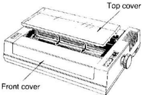
Removing the printer covers
To remove the top cover Ⓐ, lift the cover in the direction shown in Figure 2.1. Remove the front cover Ⓑ by pulling it forward and up.
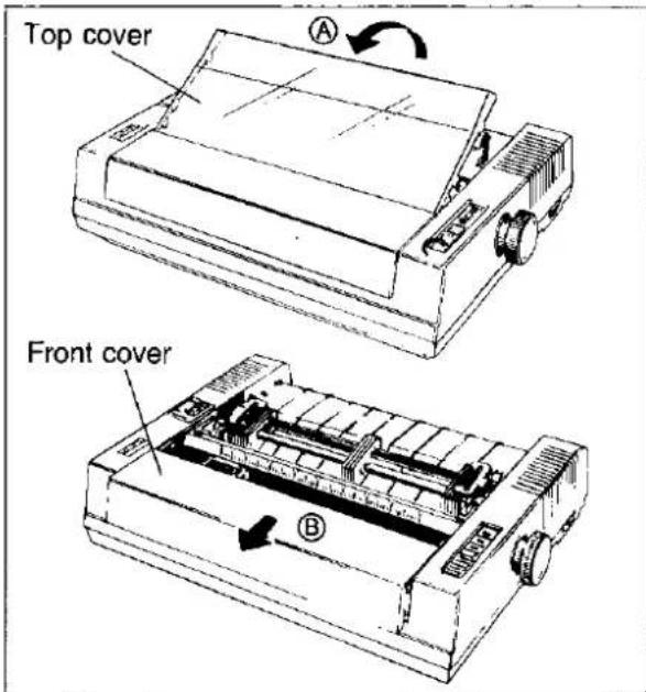
Figure 2.1 Removing the Printer Cover
- Remove the protective paper from around the platen.
Removing the carriage stoppers
During transit the print head carriage is held in place by carriage stoppers to prevent damage to the head. Remove them prior to operating the unit. Refer to Figure 2.2.
Be sure to replace them before transporting the unit.
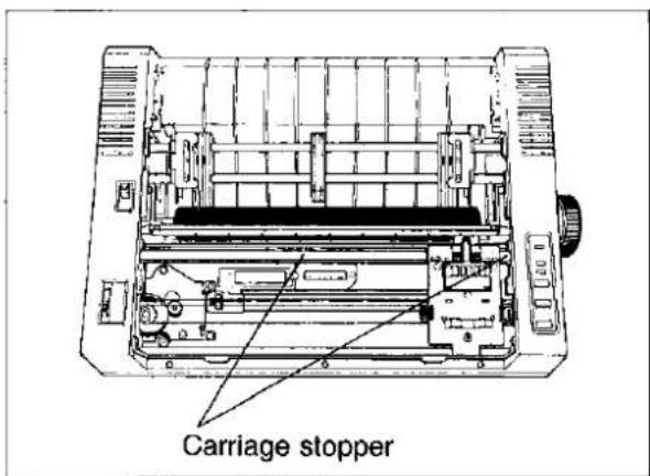
Figure 2.2 Removing the Carriage stoppers
Mounting the ribbon cassette
Make sure the printer is off. Gently slide the print head carriage toward the center of the unit. Prior to installing the cassette, remove any slack in the ribbon by rotating the knob on the cassette counterclockwise.
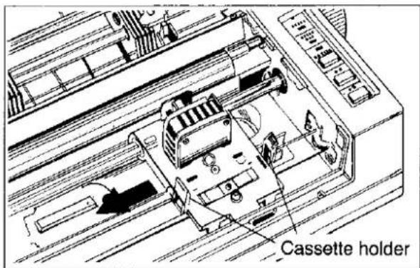
Figure 2.3A Positioning the Print Head
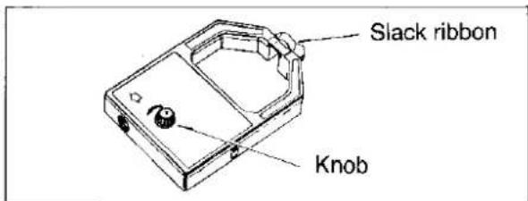
Figure 2.3B Removing the Ribbon Slack
Position the cassette over the print head and lower it in place as shown in Figure 2.3 C. Visually insure that the ribbon slips between the ribbon cover and the nose of the print head. Gently, but firmly, press down on the cassette until the two wing tabs snap into place. If the "snap" is not felt, rotate the knob slightly and press again.
Note: Rotate the knob to make sure that the ribbon is not twisted.
To remove the cassette, gently spread the wing tabs and lift up the cassette.
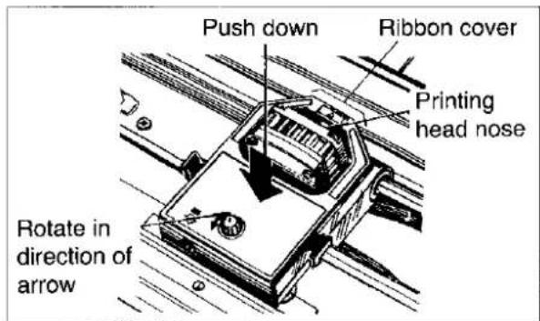
Figure 2.3C Installing the Ribbon Cassette
Mounting the paper separators
Paper separators insure the smooth flow of continuous or fanfold paper. Figures 2.4A and 2.4B show how to install the separators. First, install separator A in the holes at the top-rear of the case. Next, install separator B in the front set of holes.
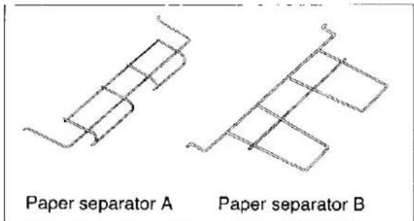
Figure 2.4A Paper Separators
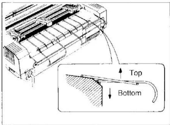
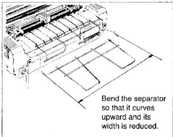
Figure 2.4B Installing the Paper Separators
Installing the paper
The printer paper feed mechanism can handle single sheets of paper or fanfold computer style paper. When using single sheets, the paper is held by pinch rollers which press the paper against the platen. For fanfold paper, the paper is pulled through the printer by the tractor mechanism.
Single Sheet
To install a single sheet of paper, follow these procedures:
- Turn the power switch ON.
- Place the PAPER FEED selector in the FRICTION position. Refer to Figure 2.5A. Raise the tear bar that is located in front of the platen.
- Feed the paper into the printer as shown in Figure 2.5B. The printer will grip the paper and rotate it about half-way around the platen.
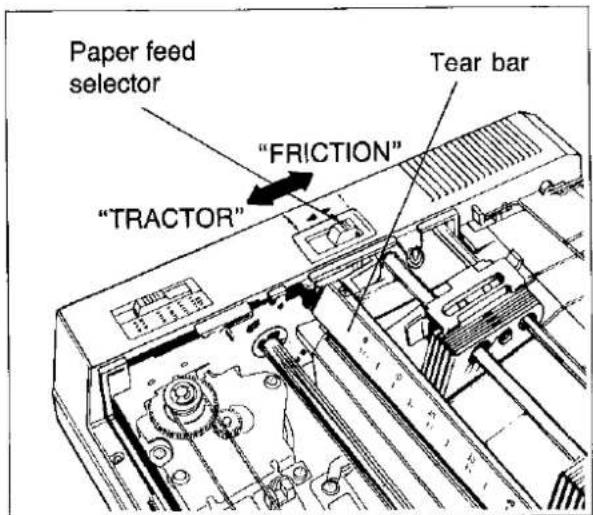
Figure 2.5A Paper Feed Selector
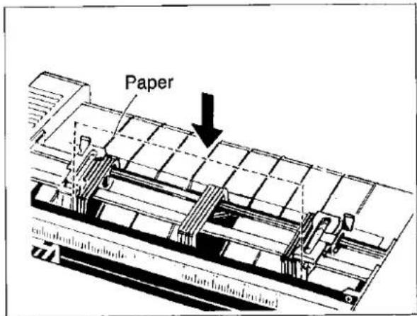
Figure 2.5B Inserting a Single Sheet
- Rotate the platen knob to advance the paper. Tuck the paper under the tear bar, then lower the bar into place.
- To align the paper horizontally or vertically, set the PAPER FEED selector to the TRACTOR position. Refer to the Figure 2.5C. This releases the pinch rollers and allows the paper to be positioned as required. Set the selector back to FRICTION before printing. Refer to Figure 2.5A.
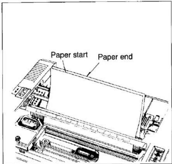
Figure 2.5C Aligning a Single Sheet
Fanfold Paper
The following steps describe how to load fanfold paper:
- Turn the power switch ON.
- Refer to Figures 2.6A and 2.6B. Unlock the tractors by pulling up on the tractor clamp levers. Slide the tractors out toward the sides and raise the covers.
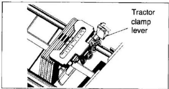
Figure 2.6A Unlocking the Tractor
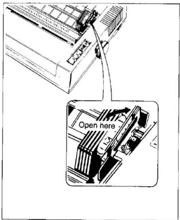
Figure 2.6B Raising the Tractor Cover
- Place the PAPER FEED selector in the FRICTION position, as you do when loading single sheets.
- Raise the tear bar that is located in front of the platen. - Feed the paper into the printer as shown in Figure 2.6C. The printer will grip the paper and rotate it about half-way around the platen.
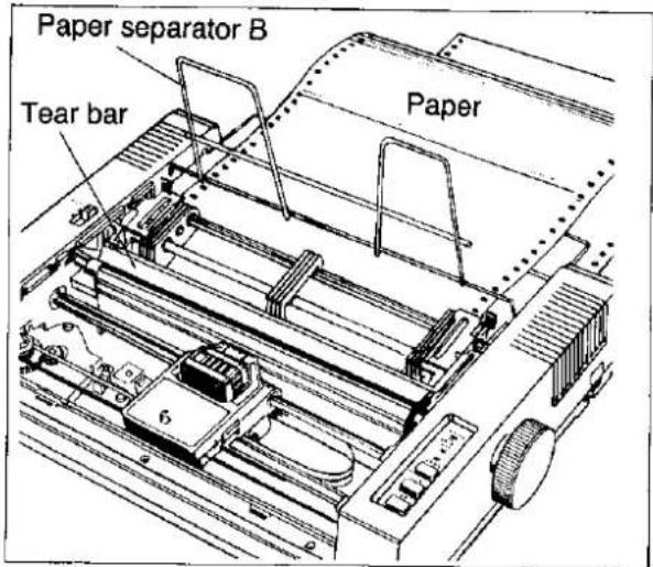
Figure 2.6C Inserting Fanfold Paper
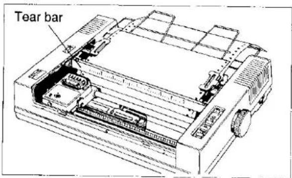
Figure 2.6D Mounting the Paper
- Rotate the platen knob to advance the paper. Tuck the paper under the tear bar, then lower the bar into place.
- Set the PAPER FEED selector to the TRACTOR position.
- Position the tractors as required to align the paper sprocket holes with the tractor pins and close the tractor covers. Refer to Figure 2.6D.
- Center the paper horizontally using the scale on the tear bar as a guide. The printer will print between 0 and 80 on the scale. Press down on the tractor clamping levers locking the tractors in place.
- To insure smooth paper flow when using fanfold paper, be sure the paper is not stacked higher than the paper separators. By feeding the paper as shown in Figure 2.7, the weight of the paper will provide reverse tension. The paper should be directly behind the printer and not off to one side.
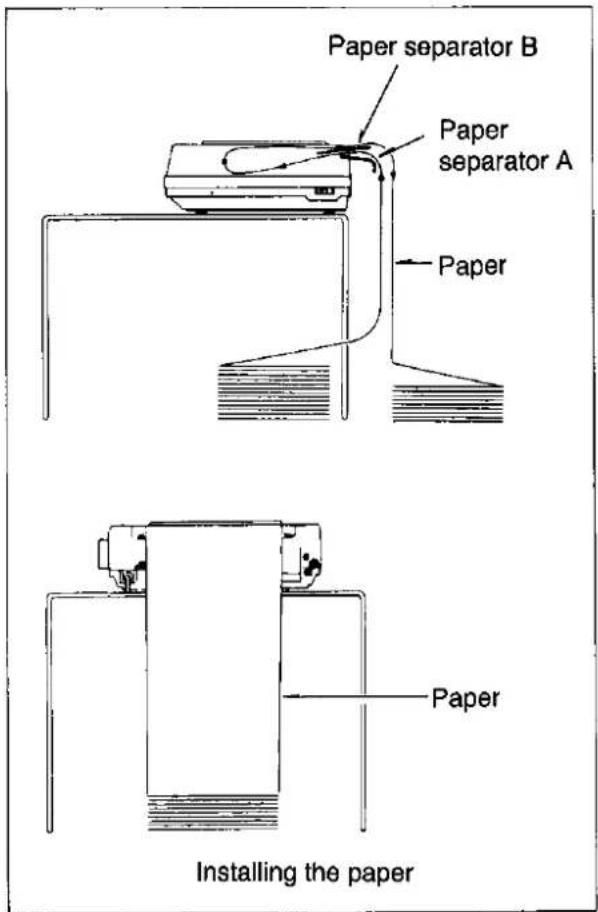
Figure 2.7 Stacking the Paper
Aligning the top of form
The printer has a line counter which keeps track of the vertical position of the print head. Each time power is turned on the line counter is reset and the current position of the head is designated as line one. This location is referred to as TOP OF FORM. When the Form Feed (FF) button is pressed, the paper will advance the length of a page. A page is defined by the Page Length Designation Command.
The first line of text will begin about 16 " (4.2 mm) from the top of the back tension plate.
(The distance between the bottom of the characters and the top of the back tension plate is about 16 " (4.2mm))
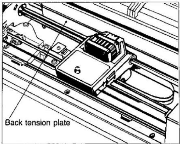
Figure 2.8 Setting the Top of Form
Adjusting the printing head gap
The distance between the printing head and platen can be adjusted to compensate for the thickness of the paper.
Note: Improper gap may cause ink smear.
Figure 2.9 shows the location of the head gap lever. Move the lever towards the platen for single sheet and away from the platen for multi-part forms.
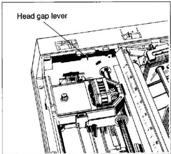
Figure 2.9 Adjusting the Print Head Gap
3.1 Switches and Indicators
Power switch
The power switch is located on the right side of the printer towards the rear. It is used to turn the AC power ON or OFF. When power is supplied to the printer the power indicator light on the front panel will be lit.
On-line switch
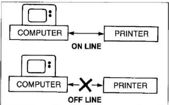
The ON LINE switch is an alternate action switch which opens and closes the communications line with the computer. When the power switch is turned on, the printer will power up in the ON LINE mode if paper is installed. If paper is not installed, the printer will power up in the OFF LINE mode. In the ON LINE mode, the printer is able to receive information from the computer and the ON LINE indicator will be lit. When OFF LINE, the indicator light will be out and the printer can no longer receive data. Refer to Figure 3.1.
flowchart
graph LR
    A["COMPUTER"] <--> B["PRINTER"]
    C["COMPUTER"] <--> D["X"]
    E["PRINTER"] --> F["ON LINE"]
    G["ON LINE"] --> H["OFF LINE"]
Figure 3.1 ON LINE & OFF LINE
When the printer is switched to ON LINE the following actions occur:
• the ON LINE light is lit
- the communications line is open between the printer and computer
• an ACK signal is sent out
- interface signal levels are:
$$ \text { B u s y } = \text { L o w } $$
$$ \text { Select } = \text { High } $$
$$ \text { Error } = \text { High } $$
When the printer is switched OFF LINE the following actions occur:
● the ON LINE light is off
● the communications line between the printer and computer is interrupted
●interface signal level are:
$$ \text { B u s y } = \text { H i g h } $$
$$ \text { Select } = \text { Low } $$
$$ \text { Error } = \text { Low } $$
Form feed switch
This switch is active in both OFF LINE and ON LINE mode. Pressing the FF switch will advance the paper from its current location to the top of the next page. Then a new top of form is established.
Line feed switch
This switch is active in both OFF LINE and ON LINE mode. Pressing this switch will cause the paper to advance one line. Multiple line feed can be accomplished by holding the switch down.
Print mode selector switch
The print mode selector switch allows the user to select one of four basic printing modes: draft, courier near letter quality (NLQ), Bold PS NLQ and compressed.
Print mode can be changed by this switch when the printer is either OFF LINE or ON LINE.
- Draft-mode (Std. Pgm.) is a high speed printing mode. The printer will print bi-directionally at 160 characters per second. This mode is used for rough drafts and preliminary documents.
Mode changes from this mode to another mode can be executed through software command.
- Courier NLQ (Courier) allows the user to print high quality documents using courier type style. The high density is achieved by a double pass of the print head.
This print mode cannot be changed to any other mode through software.
- Bold PS NLQ (Bold PS) allows the user to print high quality documents using Bold PS type style. The high density is achieved by a double pass of print head. In this mode characters are printed in proportional pitch.
This print mode cannot be changed to any other mode through software.
- Compressed-mode (Comp.) In this mode 137 characters maximum can be printed per line. Therefore printing output which is designed for wide [15.5 inches (394 mm)] paper, is possible on narrow [8.5 inches (216 mm)] paper.
This print mode cannot be changed to any other mode through software.
Refer to CHAPTER 4 for details regarding each of these modes.
Paper out indicator
The PAPER OUT indicator light is lit when there are fewer than 1.5 inches (38 mm) remaining on the paper or when no paper is inserted, and blinks in the overload condition.
3.2 Detectors
Paper out detector
The Out of Paper detector is located under the platen and senses the absence of paper. When the printer runs out of paper the PAPER OUT light is lit. The following conditions are in effect:
- the printer does not accept data from the computer
- the printer is OFF LINE and the ON LINE light is out and the alarm sounds
● the LF and FF switches are active
● the interface signal levels are:
$$ \text { Busy } = \text { High } $$
$$ \text { Select } = \text { Low } $$
$$ \text { Error } = \text { Low } $$
$$ P O = H i g h $$
To re-establish communications with the computer, insert the paper and press the ON LINE switch.
The printer will resume printing.
Do not use transparent and semitransparent paper because they are not detected.
Overload detector
An overload condition can occur when the path of the print head is blocked. During this period the following conditions are in effect.
- communication with the computer stops and the printer goes OFF LINE
●the alarm will sound at one second intervals
● the front panel switches are disabled
● the interface signal levels are:
$$ \text { B u s y } = \text { H i g h } $$
$$ \text { Select } = \text { Low } $$
$$ \text { Error } = \text { Low } $$
To reset the printer, eliminate the cause of the overload and recycle the power. The printer will resume printing.
Over heat detector
If the printer is printing continuously for extended periods of time, the printhead may become overheated. When this occurs, an internal protective circuit will cause the printer to quit printing and the alarm will sound at one second intervals. This condition will remain in effect until the head temperature decreases sufficiently, at which time the printer will automatically resume printing.
3.3 DIP Switches
Turn the power off before setting the DIP switches. The DIP switches allow the user to set certain operating conditions of the printer. Figure 3.2 shows the location of the switches and Table 3.1 is a summary of the switch settings.
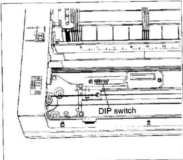
Figure 3.2 Location of DIP Switches
The switch settings are read into memory on power up. These memory locations then contain an image of the switch settings. The computer can change switch settings by downloading new commands. The International character set and the skip perforation switches, etc., can be changed in this manner. Refer to Section 4.10 for information regarding software control of the switches.
| SWITCH NUMBER | FUNCTION | ON | OFF | POSITION WHEN SHIPPED |
| SW1 | Printer Mode | Standard Mode | IBM Proprinter Mode | ON |
| SW2 | Paper Out Detector | Ineffective | Effective | OFF |
| SW3 | AUTO FEED XT | Fixed Internally | Not Fixed Internally | OFF |
| SW4 | Skip Perforation | 1 inch (25.4 mm) Skip | No Skip | OFF |
| SW5 SW6 SW7 | Character Set | SW1=ON: See International Character Set Chart SW1=OFF: See IBM Proprinter Mode Chart | OFF OFF ON | |
| SW8 | 7 bit/8 bit | 7 bit | 8 bit | OFF |
Table 3.1 DIP Switch Settings
| SW5 | SW6 | SW7 | INTERNATIONAL CHARACTER SET |
| ON | ON | ON | USA |
| OFF | ON | ON | FRANCE |
| ON | OFF | ON | ENGLAND |
| OFF | OFF | ON | ENGLAND |
| ON | ON | OFF | DENMARK I |
| OFF | ON | OFF | SWEDEN |
| ON | OFF | OFF | ITALY |
| OFF | OFF | OFF | SPAIN |
Table 3.2 International Character Set
| PRINTER MODE SW1 |
ON Standard Mode
OFF IBM Proprinter mode
Each printer mode has the following character set. IBM character sets are selected by SW7 when SW1 is set to OFF.
Standard Mode
| ASCII | = 96 |
| Italic ASCII | = 96 |
| International | = 32 |
| Italic International | = 32 |
IBM Character Set 1
| ASCII | = 96 |
| Special Characters | = 95 |
IBM Character Set 2
| ASCII | = 96 |
| Special Characters | =132 |
Refer to APPENDIX A for the character set charts.
| SWITCH NUMBER | FUNCTION | ON | OFF |
| SW5 | Automatic CR | Causes Automatic CR on LF, VT, ESC+J | Prevents Automatic CR on LF, VT, ESC+J |
| SW6 | Zero font | ∅ | 0 |
| SW7 | Character Set | Set 2 | Set 1 |
Table 3.3 IBM Proprinter Mode
PAPER OUT DETECTOR SW2
ON Paper out detector is not active and printing is possible in paper out condition (paper out indicator will be lit). When using single sheets printing is possible in the last 1.5 inches (38 mm) of the sheet.
OFF Paper out detector is active and printing will automatically stop at the paper out condition.
AUTO FEED XT SW3
ON A Line Feed command (LF) is added to each Carriage Return (CR).
OFF Carriage Return only.
SKIP PERFORATION SW4
ON A 3 line margin is skipped before and after the perforation between pages.
OFF Printing Is continuous, NO margins around perforation.
The setting can be changed by software. Refer to page 4-65.
CHARACTER SET SW5, 6 & 7.
The combination of these switch settings is used with the DIP switch 1 setting to select one of 7 International character sets or IBM Proprinter Modes. The character set diagrams are located in APPENDIX A.
The International character sets are selected when the DIP switch 1 is set to ON.
The IBM Proprinter modes are selected when the DIP switch 1 is set to OFF.
7/8 BIT CODE SELECTION SW8
ON=7 BIT
OFF=8 BIT
This switch selects the size of the data word. If the computer sends a 7 bit word, the printer must also be set for 7 bits. If the two settings do not agree, random errors will occur and meaningful communication will not be possible. Refer to Section 4.7 for information regarding 7 bit and 8 bit formatting.
3.4 | Initialization
A. Power up sequence
The following procedures should be followed when turning the printer on:
- Ensure the carriage stoppers have been removed.
- Set the DIP switches as required.
- Be sure the ribbon is installed correctly.
- Plug the power cord into an appropriate wall outlet and turn the power ON.
- Load the paper and set the paper feed selector.
B. Initialization
The printer is initialized under the following conditions:
—the AC power is turned on
—the PRIME signal is received
—the RESET command is received (Standard mode only)
When the printer is initialized, the following conditions are set:
—the print head goes to the home leftmost position
—the print buffer is cleared
—the receive buffer is cleared (not cleared by RESET command)
—vertical tab settings are cleared
—horizontal tabs are set every 8 columns
—the DIP switches are read and printer modes set
—print mode is subject to the position of print mode selector switch
—present form position is designated as top of form
—all modes set by control and escape commands will be cleared
—the printer goes ON LINE
3.5 Self Test
The printer has a self test feature which allows the user to test the printer independent of a computer. The mode is entered by turning on the power switch while pressing down the line feed (LF) switch. All 96 ASCII characters will be printed continuously across the width of the platen until the power is turned off.
The self test printing stops automatically in approximately 30 minutes (with draft character printing).
It is possible to print out a list of the current DIP switch settings, allowing the user to check the settings without moving the printer. This feature is activated by turning on the power while pressing the FF switch. The printout will list all the possible settings of each switch with the current setting underlined.
3.6 | Hex. Dump
The HEX. DUMP mode is activated by turning on the power while pressing both the line feed (LF) and form feed (FF) switches. In this mode, all data received from the computer is printed in hex code rather than the normal ASCII characters. Function codes for the printer (CR, LF, HT, etc.) are not executed. To reset the mode, turn the power off, then back on.
3.7 Receive Buffer
The printer has a receive buffer of 1K bytes. This can reduce the computer's idle time caused by waiting for a printer to complete its printing. Therefore total throughput of the whole system will be increased. When the printer is OFF LINE and the receive data remain in the buffer, the buzzer sounds repeatedly (alarm sound) and indicates the data existence in buffer.
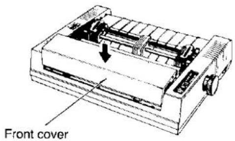
3.8 | Replacing the Covers
First, insert the front cover as shown in Figure 3.3A. Then push in as shown in Figure 3.3B.
3.3A.
3.3B.
natural_image
Technical line drawing of a mechanical device with internal components and an arrow indicating motion (no text or symbols)Figure 3.3 Replacing the Front Cover
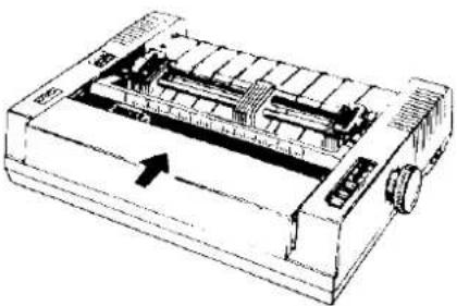
Insert the top cover (Figure 3.4A) such that the tabs on the front side slip under the front cover. Then push down so that the tabs on the side snap into places (Figure 3.4B).
3.4A.
3.4B.
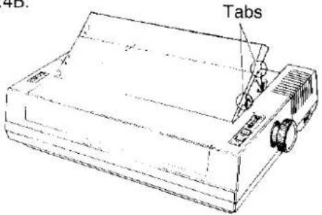
Figure 3.4 Replacing the Top Cover
4.1 Introduction
In order for a computer to communicate with a printer, both pieces of equipment must understand a common language or coding scheme. One such coding scheme is called ASCII (American Standard Code for Information Interchange). As an example, the ASCII code for the character "K" can be expressed in any of the following forms:
(01001011) _2 —Binary
4B HEX, 4B—Hexadecimal
75 dec, 75—Decimal
Many computers allow you to enter ASCII codes in hexadecimal form. Most computers which support ASCII allow the input to be in decimal form. Many allow you to enter the code in either form. Once entered, the ASCII codes are converted to binary form by the computer and then sent to the printer.
In the sections which follow, you will see how to enter various ASCII codes to enable the printer to perform the functions you would like. Since the decimal equivalent of the ASCII code is most commonly used, all examples which follow will use the decimal form.
Appendix A contains the ASCII character and control command tables used by this printer.
4.2 Control Codes
The various printer functions are set through the use of control codes, which consist of one or more ASCII characters entered into the computer in a special way. These control codes often differ from printer to printer. Control codes generally fall into two categories: one-byte control codes and multi-byte control codes. The multi-byte control codes are often referred to as Escape Sequences since each code begins with the ASCII code for the ESCAPE character (ESC). Such an ESC character should not be confused with the Escape Key found on some computer keyboards.
Control codes can be sent to this printer from your computer in different ways. The three most common ways are:
- Through commercial software packages
- Directly from the keyboard
- From within a user-written program
The latter two methods will specifically reference the BASIC language, although other languages such as FORTRAN, PASCAL, etc., can also be used. We will use BASIC since it is relatively easy language to use. In addition it is the most commonly used microcomputer language.
4.3 Entering Control Codes through Commercial Software Packages
Many computer users do not have the time, the expertise, or the interest to develop software suited for their applications. In such cases software written by professionals can be purchased. Such software should be selected not only to meet the needs of the user, but must also be compatible with both computer and printer.
Commercial software is often written with what is called a driver. A driver is that part of the software which allows the user to configure the package to the type of printer and interface being used. Once the software has been booted, the user is generally requested to supply additional information such as:
- Brand/Model of printer being used.
- Slot number in which interface card is installed.
- Baud rate, parity, etc. if a serial interface is being used.
Once the necessary information has been supplied, the software will provide the computer with the control codes and other data needed by this printer.
Many word processing packages will request that you enter the ASCII codes used by this printer for special settings such as underlining, compressed print, super- and subscript, italics, etc.. In all cases you should refer to your software instruction manual for the proper use of the package with this printer.
4.4 Entering Control Codes Directly from the Keyboard
With many computers, the BASIC language is ready to use once you power up. With others, BASIC must be loaded from cassette or disk. In any case, once BASIC is ready, you may then enter this printer control commands directly from your computer keyboard.
BASIC requires the use of the PRINT command (or LPRINT, PRINT#, etc. depending on the type of BASIC your computer uses) to process and send the control commands to this printer. As part of this PRINT command, you must supply the appropriate ASCII code(s) for the CHR\$ function.
For example, the command: LPRINT CHR\$(15) followed by a RETURN will set this printer to compressed mode. Subsequent output to this printer will appear in compressed mode.
If, after issuing the above command, subsequent PRINT statements output nothing to the printer, check for one or more of the following:
- Have you indicated to the computer that output is to the printer and not the screen? For example, PR#1, say, causes subsequent PRINT statements on the Apple® computer to PRINT the printer and not the screen. LPRINT do the same in Microsoft® BASIC.
- Is this printer on line? If not, press the green ON LINE button on the front panel.
- Is the interface cable plugged into the computer and printer?
- When using a serial interface, is the baud rate setting on the printer the same as that on the computer or interface card?
Notice that when you enter a BASIC command directly from the keyboard, you do NOT use a line number as you would in a BASIC program. Moreover, control codes may be entered only one line at a time.
4.5 Entering Control Codes from Within a Program
Control commands may also be entered from within a BASIC program. The advantage to this technique is that you can incorporate a number of different control commands into a single program and therefore produce output with a variety of special features. This is done by RUNning your program once. In this case BASIC requires that each line in your program be preceded by a line number.
As an example, we mentioned earlier that the command LPRINT CHR\$(15) entered directly from the keyboard will set compressed print on this printer. From within a BASIC program, this command might be:
50 LPRINT CHR\$(15)
The remainder of this chapter will show you how to enter each of the control commands which this printer uses. All examples will be IBM-PC® BASIC programs which use LPRINT to access the printer and use decimal numbers for the ASCII codes.
4.6 Entering Hexadecimal Code
In the event that you will be entering ASCII codes in hexadecimal form, you must supply two extra characters per code. These are the ampersand (&) and the letter H. The example below illustrates the BASIC command to set compressed print on this printer.
Decimal
LPRINT CHR\$(15)
Hexadecimal
LPRINT CHR\$(&HOF)
Refer to Appendix A for the ASCII code table.
4.7 Control Codes
A number of the printer control commands require only a single ASCII-coded character as part of the LPRINT statement. The command LPRINT CHR\$(15) which we discussed earlier is an example of a single-byte control command.
Multi-byte control codes, often called Escape control codes or Escape sequences, always begin with an ESC designation. ESC is designated by CHR\(27) in decimal form or CHR\(&H1B) in hexadecimal form. The ESC designation is always followed by one or more additional codes, hence, the name multi-byte control code.
In BASIC, these two or more bytes are joined (or concatenated) into a single command or string using either a plus (+) sign, a semicolon (;), or by neither symbol but rather by listing one byte after another without any spaces. BASIC on many computers allows you to use any of these formats. Refer to your BASIC manual for the proper method of string concatenation.
Table 4.1 shows equivalent methods of entering multi-byte control commands for most computers.
There is one remaining input format commonly used to reduce the keystrokes necessary to enter a multi-byte control command. As you examine the multi-byte control commands in the pages ahead, you will notice that the second byte, with the exception of ESC+SO and ESC+SI, is always a character which appears somewhere on your keyboard. In such cases, rather than enter that character's ASCII code as part of the CHR\$ function, you may simply enter that character in quotes ("). For example, to set pica pitch (ESC+P), you may enter:
LPRINT CHR\(27)+CHR\(80);
or
LPRINT CHR\$(27) + "P";
As another example, to set double width printing, you may enter:
LPRINT CHR\(27)+CHR\(87)+CHR\$(1);
or
LPRINT CHR\(27) + "W" + CHR\(1);
With this method, any of the three input formats shown in Table 4.1 may also be used (subject to the BASIC you are using).
Multi-byte control codes can be summarized by the following classifications:
-Font Selection
●Character Pitch Selection
●Character Highlight Selection
●Character Set Selection
●Bit Image (Graphics) Mode Selection
●Paper Feed Control
- Page Format Control
-Tabulation
●Carriage Control
- Data Control
●Downloadable Character Selection
- Miscellaneous
NOTE: Certain programs in this section include OPEN, WIDTH, PRINT, and CLOSE statements. These BASIC statements are necessary on many IBM compatible computers to avoid unwanted "breaks" in output. Refer to page 4-38 for additional information. PRINT #1 does not generate CR and LF, therefore CR and LF must be used when they are required.
| Two-Byte Command | Three-Byte Command | |
| FunctionNameCode | Set Pica PitchESC+P27,80 DEC | Set Double Width PrintingESC+W+127,87,1 DEC |
| Input Format 1Input Format 2Input Format 3 | LPRINT CHR(27)+CHR(80);LPRINT CHR(27);CHR(80);LPRINT CHR(27)CHR(80); | LPRINT CHR(27)+CHR(87)+CHR(1);LPRINT CHR(27);CHR(87);CHR(1);LPRINT CHR(27)CHR(87)CHR$(1); |
Table 4.1 Input Formats
FONT SELECTION
The term font refers to a particular style, shape, or design of a set of characters. Font selection commands will enable you to select a particular character set design from a variety of such designs, thereby producing greater flexibility in the appearance of your final document.
Special fonts available on this printer include Italic, Subscript, Superscript, and Near Letter Quality. While there does exist a Draft font, the command for selecting this font also selects 10 pitch (10 characters per inch (25.4 mm)). This command, then, will be discussed in the section on pitches.
ITALIC FONT:
(Standard Mode only)
Selects italic character printing.
Name: Setting: ESC+4
Release: ESC+5
Code: Setting: 27,52 DEC 1B,34 HEX
Release: 27,53 DEC 1B,35 HEX
Input Format: Setting: LPRINT CHR\$(27) + "4";
Release: LPRINT CHR\$(27) + "5";
Example: 10 REM ITALIC SETTING/RELEASE
20 LPRINT CHR\$(27)+"4";
30 LPRINT "ITALIC CHARACTERS ON"
40 LPRINT CHR\$(27)+"5";
50 LPRINT "ITALIC CHARACTERS OFF"
60 END
ITALIC CHARACTERS ON
ITALIC CHARACTERS OFF
Comments:
- Italic characters can be printed in the near letter quality font and in proportional spacing.
- Italic characters in locations 160 DEC-254 DEC (A0 HEX-FE HEX) are printed in place of characters in locations 32 DEC-126 DEC (20 HEX-7E HEX).
NEAR LETTER QUALITY (NLQ) FONT:
(Standard Mode only)
Selects near letter quality font printing.
| Name: | Courier NLQ Setting: | ESC+x+n | n=1,49,129,177 |
| Bold PS NLQ Setting: | ESC+x+n | n=2,50,130,178 | |
| Release: | ESC+x+m | m=0,48,128,176 |
| Code: | Setting: 27,120,n DEC | 1B,78,n HEX |
| Release: 27,120,m DEC | 1B,78,m HEX |
| Input Format: Setting: LPRINT CHR(27) + "x" + CHR(n); |
| Release: LPRINT CHR(27) + "x" + CHR(m); |
| Example: | 10 REM NEAR LETTER QUALITY FONT |
| 20 LPRINT "PRINTING USING THE DRAFT FONT" | |
| 30 LPRINT CHR(27)+"x"+CHR(1); | |
| 40 LPRINT "PRINTING USING THE COURIER NLQ FONT" | |
| 50 LPRINT CHR(27)+"x"+CHR(2); | |
| 60 LPRINT "PRINTING USING THE BOLD PS NLQ FONT" | |
| 70 LPRINT CHR(27)+"x"+CHR(0); | |
| 80 LPRINT "PRINTING USING THE DRAFT FONT" | |
| 90 END |
| PRINTING USING THE DRAFT FONT |
| PRINTING USING THE COURIER NLQ FONT |
| PRINTING USING THE BOLD PS NLQ FONT |
| PRINTING USING THE DRAFT FONT |
Comments:
- This command sets near letter quality printing in whichever pitch is set at the time.
- Near letter quality characters are printed with two passes of the print head. Therefore double printing by ESC+G is ineffective in near letter quality printing.
- Sub/superscript characters can be printed in the near letter quality font.
- Fonts are set as follows:
n=0: Draft font
n=1: Courier NLQ font
n=2: Bold PS NLQ font
- When setting Bold PS NLQ font (n=2), characters are printed using proportional spacing. If other pitch select command is executed after ESC+x+2, the pitch will be changed.
SUPERSCRIPT FONT:
Selects superscript font with characters printed on the top-half of the line. Characters are reduced to 12 their original height.
| Name: | Setting: | ESC+S+n | n=0,48,128,176 |
| Release: | ESC+T |
| Code: | Setting: 27,83,n DEC | 1B,53,n HEX |
| Release: 27,84 DEC | 1B,54 HEX |
| Input Format: Setting: LPRINT CHR(27) + “S” + CHR(n);Release: LPRINT CHR$(27) + “T”; |
| Example: | (See SUBSCRIPT.) |
Comments:
- Superscript characters are normal width.
- To print very small characters, such as exponents, set superscript and compressed modes simultaneously.
- Superscript characters can be printed in the near-letter-quality mode.
- ESC+T also releases the subscript print setting.
• See subscript comments.
SUBSCRIPT FONT:
Selects subscript font with characters printed on the bottom-half of the line. Characters are reduced to 12 their original height.
| Name: | Setting: ESC+S+m | m=1,49,129,177 |
| Release: ESC+T |
| Code: | Setting | 27,83,m DEC | 1B,53,m HEX |
| Release: | 27,84 DEC | 1B,54 HEX |
| Input Format: Setting: LPRINT CHR(27) + "S" + CHR(m);Release: LPRINT CHR$(27) + "T"; |
| Example: | 10 REM SUPER/SUB SCRIPT |
| 20 LPRINT CHR(27) + "-" + CHR(1); | |
| 30 LPRINT CHR(27) + "S" + CHR(0); | |
| 40 LPRINT "ABCDEFGHIJKLMN - SUPERSCRIPT" | |
| 50 LPRINT CHR(27) + "S" + CHR(1); | |
| 60 LPRINT "ABCDEFGHIJKLMN - SUBSCRIPT" | |
| 70 LPRINT CHR(27) + "T"; | |
| 80 LPRINT "ABCDEFGHIJKLMN" | |
| 90 LPRINT CHR(27) + "-" + CHR$(0); | |
| 100 END | |
| ABCDEFGHIJKLMNOPQRSTUVWXYZCRIPT | |
| ABCDEFGHIJKLMNOPQRSTUVWXYZCRIPT |
Comments:
- Subscript characters are normal width.
- To print very small characters, such as exponents, set subscript and compressed modes simultaneously.
- Subscript characters can be printed in the near letter quality mode.
-ESC+T also releases the superscript print setting. - In both the subscript and superscript modes, the printer performs double-strike, single direction printing. Following the first pass of the print head, the paper is fed 1/216 inch (0.12 mm), and the line is printed again. The printer automatically compensates for the paper feed to maintain the proper line count.
PRINT MODE SELECT:
Selects the printing fonts and quality
(IBM Proprinter Mode only)
Name: ESC+I+n n=0,2,4,6
Code: 27,73,n DEC 1B,49,n HEX
Input Format: LPRINT CHR\(27) + "T" + CHR\(n);
Example:
10 REM PRINTING FONTS AND QUALITY SELECTS
20 LPRINT CHR(27) + "=" + CHR(67) + CHR(0) + CHR(20) + "A";
30 FOR I = 1 TO 5
40 LPRINT CHR(0) + CHR(0);
50 LPRINT CHR(0) + CHR(0) + CHR(2) + CHR(7);
60 LPRINT CHR(7) + CHR(7) + CHR(254) + CHR(64);
70 LPRINT CHR(64) + CHR(48) + CHR$(0);
80 NEXT I
90 FOR I = 0 TO 6 STEP 2
100 LPRINT CHR(27) + "I" + CHR(0);
110 LPRINT "n = "; I;
120 LPRINT CHR(27) + "I" + CHR(I);
130 LPRINT "ABCDE"
140 NEXT I
150 END
n = 0 ABCDE
n = 2 ABCDE
n = 4 ♩♩♩♩♩
n = 6 ♩♩♩♩♩
Comment:
●This command selects the Character Generator (ROM CG or DOWNLOAD character) and printing fonts.
n=0: Internal characters draft fonts.
n=2: Internal characters NLQ fonts.
n=4: Download characters draft fonts.
n=6: Download characters NLQ fonts.
- When n = 4 , the second of horizontal two adjacent columns will not be fired. When n = 6 (download NLQ font), all columns will be fired and double spiked characters will be printed.
NLQ PRINTING:
Selects near letter quality font printing.
(IBM Proprinter Mode only)
Name: Setting: ESC+G Release: ESC+H
Code: Setting: 27,71 DEC 1B,47 HEX Release: 27,72 DEC 1B,48 HEX
Input Format: Setting: LPRINT CHR\(27) + "G" ; Release: LPRINT CHR\(27) + "H" ;
Example: 10 REM NEAR LETTER QUALITY FONT 20 LPRINT "PRINTING USING THE DRAFT FONT" 30 LPRINT CHR\$(27)+"G"; 40 LPRINT "PRINTING USING THE NLQ FONT" 50 LPRINT CHR\$(27)+"H"; 60 LPRINT "PRINTING USING THE DRAFT FONT" 70 END
PRINTING USING THE DRAFT FONT PRINTING USING THE NLQ FONT PRINTING USING THE DRAFT FONT
Comments:
- This command sets near letter quality (Courier) printing in whichever pitch is set at the time.
- When emphasized and NLQ printing modes (set by ESC+G) are set simultaneously, emphasized and double struck draft font characters are printed.
CHARACTER PITCH SELECTION
The term pitch as it pertains to dot matrix printers refers to the number of characters which can be printed in one inch (25.4 mm). This includes 10, 12, 15, 17 characters per inch, and proportional spacing.
DRAFT PICA PITCH:
(Standard Mode only)
Sets draft pica pitch (10 characters per inch) printing.
Name: ESC+P
Code: 27,80 DEC 1B,50 HEX
Input Format: LPRINT CHR\$(27) + "P";
Example: 10 REM DRAFT PICA PITCH
20 LPRINT CHR\$(27)+"P";
30 LPRINT "PICA"
40 FOR I=1 TO 3
50 LPRINT "ABCDE";
60 NEXT I
70 LPRINT CHR\$(10);
80 END
FICA
ABCDEABCDEABCDE
Comments:
- Setting pica pitch produces 10 characters per inch or 80 characters per line.
- Pica pitch can be changed to elite, proportional, compressed, etc. by entering the appropriate control commands.
- ESC+P releases the near letter quality font and subsequent output is printed using draft font.
- If ESC+P is executed after compressed printing has been set, draft font is printed at 17 characters per inch.
- If ESC+P is executed after proportional spacing has been set, draft font is printed using proportional spacing.
DRAFT ELITE PITCH:
(Standard Mode only)
Sets draft elite pitch (12 characters per inch) printing.
Name: ESC+M
Code: 27,77 DEC 1B,4D HEX
Input Format: LPRINT CHR\$(27) + "M";
Example: 10 REM DRAFT ELITE PITCH
20 LPRINT "----DRAFT PICA----"
30 LPRINT CHR\$(27)+"M";
40 LPRINT "----DRAFT ELITE----"
50 END
----DRAFT PICA---- ----DRAFT ELITE----
Comments:
- Setting elite pitch produces 12 characters per inch or 96 characters per line.
- Compressed printing and proportional spacing cannot be printed using the elite pitch. In the elite pitch, the compressed print or proportional spacing setting will be ignored. If the elite pitch designation is made after compressed printing or proportional spacing has been set, compressed printing or proportional spacing is released and the elite pitch remains in effect.
- ESC+M releases the near letter quality font and subsequent output is printed using the draft font.
ELITE PITCH:
(IBM Proprinter Mode only)
Sets printing to 12 characters per inch (96 characters per line).
Name: Setting: ESC+: Release: DC2
Code: Setting: 27,58 DEC 1B, 3A HEX Release: 18 DEC 12 HEX
Input Format: Setting: LPRINT CHR\(27)+“ :”; Release: LPRINT CHR\(18);
Example: 10 REM ELITE PITCH 20 LPRINT CHR\$(27)+";"; 30 LPRINT "----ELITE---- 40 LPRINT CHR\$(18); 50 LPRINT "----PICA---- 60 END
ELITE PICA
Comments:
- The elite and compressed modes cannot be used together. In the elite pitch, the compressed print setting will be ignored.
- If the elite pitch designation is made after compressed mode has been set, compressed mode is released and the elite pitch remains in effect.
●This command does not affect Draft or NLQ font mode.
NEAR LETTER QUALITY—PICA PITCH:
(Standard Mode only)
Sets near letter quality pica pitch (10 characters per inch) printing.
Name: ESC+n
Code: 27,110 DEC 1B,6E HEX
Input Format: LPRINT CHR\$(27) + "n";
Example: 10 REM NEAR LETTER QUALITY, PICA PITCH
20 LPRINT CHR\$(27)+"n";
30 LPRINT "NLQ PICA PITCH"
40 LPRINT "NLO PICA PITCH WITH";
50 LPRINT CHR\(27) + "S" + CHR\(1);
60 LPRINT "SUBSCRIPT";
70 LPRINT CHR\(27) + "S" + CHR\(0);
80 LPRINT "SUPERSCRIPT"
90 LPRINT CHR\$(27)+"T"
100 LPRINT CHR\$(27) + "P"
110 END
NLQ PICA PITCH
NLQ PICA PITCH WITH SUBSCRIPT ^SUPERSCRIPT
Comments:
- If ESC+n is executed after compressed printing has been set, near letter quality font is printed at 17 characters per inch.
- If ESC+n is executed after proportional spacing has been set, near letter quality font is printed using proportional spacing.
- Near letter quality characters are printed with two passes of the print head. Therefore double printing by ESC+G is ineffective in the near letter quality pica pitch.
- Sub/superscript characters can be printed using near letter quality pica pitch characters.
- ESC+P releases near letter quality pica pitch and sets printing to draft pica pitch.
NEAR LETTER QUALITY—ELITE PITCH:
(Standard Mode only)
Sets near letter quality elite pitch (12 characters per inch) printing.
Name: ESC+o
Code: 27,111 DEC 1B,6F HEX
Input Format: LPRINT CHR\$(27) + "o";
Example: 10 REM NEAR LETTER QUALITY, ELITE PITCH
20 LPRINT CHR$(27)+"o";
30 LPRINT "NLQ ELITE PITCH"
40 LPRINT "NLQ ELITE PITCH WITH ";
50 LPRINT CHR(27)+"S"+CHR(1);
60 LPRINT "SUBSCRIPT";
70 LPRINT CHR(27)+"S"+CHR(0);
80 LPRINT "SUPERSCRIPT"
90 LPRINT CHR$(27)+"T";
100 LPRINT CHR$(27)+"P";
110 LPRINT "DRAFT PICA PITCH"
120 END
NLQ ELITE PITCH
NLQ ELITE PITCH WITH SUBSCRIPT ^SUPERSCRIPT
DRAFT PICA PITCH
Comments:
- If near letter quality elite pitch and compressed printing or proportional spacing are set simultaneously, compressed printing or proportional spacing will be ignored and elite near letter quality characters will be printed.
- Near letter quality characters are printed with two passes of the print head. Therefore double printing by ESC+G is ineffective in near letter quality elite pitch.
- Sub/superscript characters can be printed using near letter quality elite pitch characters.
- ESC+P releases near letter quality elite pitch and sets printing to draft pica pitch.
COMPRESSED PITCH:
Sets compressed pitch (17 characters per inch) printing.
Name: Setting: SI or ESC+SI
Release: DC2
Code: Setting: 15 or 27,15 DEC 0F or 1B,0F HEX
Release: 18 DEC 12 HEX
Input Format: Setting: LPRINT CHR\$(15);
or
LPRINT CHR\(27)+CHR\(15);
Release: LPRINT CHR\$(18);
Example:
10 REM COMPRESSED PITCH
20 LPRINT "DRAFT PICA PITCH - 10 CHARACTERS PER INCH"
30 LPRINT CHR$(15);
40 LPRINT "COMPRESSED PITCH USING (SI) - 17 CHARACTERS PER INCH"
50 LPRINT CHR$(18);
60 LPRINT "BACK TO DRAFT PICA PITCH - 10 CHARACTERS PER INCH"
70 LPRINT CHR(27)+CHR(15);
80 LPRINT "COMPRESSED PITCH USING (ESC+SI) - 17 CHARACTERS PER INCH"
90 LPRINT CHR$(18);
100 LPRINT "BACK TO DRAFT PICA PITCH - 10 CHARACTERS PER INCH"
110 END
DRAFT PICA PITCH - 10 CHARACTERS PER INCH
COMPRESSED PITCH USING (SI) - 17 CHARACTERS PER INCH
BACK TO DRAFT PICA PITCH - 10 CHARACTERS PER INCH
COMPRESSED PITCH USING (ESC+SI) - 17 CHARACTERS PER INCH
BACK TO DRAFT PICA PITCH - 10 CHARACTERS PER INCH
Comments:
- Setting compressed pitch produces 17 characters per inch or 137 characters per line.
- When emphasized and compressed characters are set simultaneously, compressed printing is ignored and emphasized characters are printed. However, when emphasized printing is released, characters are printed in compressed pitch. Use DC2 to release compressed pitch.
PROPORTIONAL SPACING:
(Standard Mode only)
Sets proportional spacing between characters.
| Name: | Setting: ESC+p+n | n=1,49,129,177 |
| Release: ESC+p+m | m=0,48,128,176 |
| Code: | Setting: 27,112,n DEC | 1B,70,n HEX |
| Release: 27,112,m DEC | 1B,70,m HEX |
| Input Format: Setting: LPRINT CHR(27) + "p" + CHR(n); Release: LPRINT CHR(27) + "p" + CHR(m); |
Example:
10 REM PROPORTIONAL SPACING
20 LPRINT "DRAFT PICA PITCH:"
30 LPRINT " ABCDEFGHIJKLMNOPQRSTUVWXYZabcdefghijklmnopqrstuvwxyz"
40 LPRINT CHR\(27) + "p" + CHR\(1);
50 LPRINT "PROPORTIONAL SPACING:"
60 LPRINT " ABCDEFGHIJKLMNOPQRSTUVWXYZabcdefghijklmnopqrstuvwxyz"
70 LPRINT CHR\$(27)+"n";
80 LPRINT "COURIER NLQ PROPORTIONAL SPACING:"
90 LPRINT " ABCDEFGHIJKLMNOPQRSTUVWXYZabcdefghijklmnopqrstuvwxyz"
100 LPRINT CHR\$(27) + "P";
110 LPRINT CHR\(27)+"p"+CHR\(0);
120 END
DRAFT PICA PITCH:
ABCDEFGHIJKLMNOPQRSTUVWXYZabcdefghijklmnopqrstuvwxyz
PROPORTIONAL SPACING:
ABCDEFGHIJKLMNOPQRSTUVWXYZabcdefghijklmnopqrstuvwxyz
COURIER NLQ PROPORTIONAL SPACING:
ABCDEFGHIJKLMNOPQRSTUVWXYZabcdefghijklmnopqrstuvwxyz
Comments:
- When using proportional spacing in draft font printing mode, characters are printed as emphasized, not draft characters. Refer to table 4.2 for proportional spacing table.
- Proportional spacing can be invoked only when in pica pitch. If proportional spacing is set together with compressed printing, compressed printing is ignored and characters are printed using proportional spacing.
- When proportional spacing is released, characters are printed in pica pitch.
| ASCII code | Char. | Width |
| 0 | A | 12 |
| 1 | B | 12 |
| 2 | C | 11 |
| 3 | D | 10 |
| 4 | E | 8 |
| 5 | F | 12 |
| 6 | G | 12 |
| 7 | H | 12 |
| 8 | I | 12 |
| 9 | J | 12 |
| 10 | K | 11 |
| 11 | L | 12 |
| 12 | M | 12 |
| 13 | N | 12 |
| 14 | O | 12 |
| 15 | P | 12 |
| 16 | Q | 12 |
| 17 | R | 12 |
| 18 | S | 12 |
| 19 | T | 12 |
| 20 | U | 12 |
| 21 | V | 12 |
| 22 | W | 12 |
| 23 | X | 12 |
| 24 | Y | 12 |
| 25 | Z | 12 |
| 26 | A | 12 |
| 27 | B | 12 |
| 28 | C | 12 |
| 29 | D | 12 |
| 30 | E | 12 |
| 31 | F | 12 |
| 32 | G | 12 |
| 33 | H | 12 |
| 34 | I | 12 |
| 35 | J | 12 |
| 36 | K | 12 |
| 37 | L | 12 |
| 38 | M | 12 |
| 39 | N | 12 |
| 40 | O | 12 |
| 41 | P | 12 |
| 42 | Q | 12 |
| 43 | R | 12 |
| 44 | S | 12 |
| 45 | T | 12 |
| 46 | U | 12 |
| 47 | V | 12 |
| 48 | W | 12 |
| 49 | X | 12 |
| 50 | Y | 12 |
| 51 | Z | 12 |
| 52 | A | 12 |
| 53 | B | 12 |
| 54 | C | 12 |
| 55 | D | 12 |
| 56 | E | 12 |
| 57 | F | 12 |
| 58 | G | 12 |
| 59 | H | 12 |
| 60 | I | 12 |
| 61 | J | 12 |
| 62 | K | 12 |
| 63 | L | 12 |
Table 4.2 Proportional Spacing: Standard Mode Characters Unit: 1120 inch (0.21 mm)
PROGRAMMABLE PITCH:
(Standard Mode only)
Sets a character pitch at 10, 12, 15, 17, or proportional spacing.
Name: ESC+w+n n=0,1,2,3,4
Code: 27,119,n DEC 1B,77,n HEX
Input Format: LPRINT CHR\(27) + "w" + CHR\(n);
Example: 10 REM PROGRAMMABLE PITCH
20 FOR L=1 TO 2
30 IF L=1 THEN LPRINT "DRAFT FONT:":GOTO 50
40 LPRINT CHR$(27)+"n";"NEAR LETTER QUALITY FONT:"
50 FOR I=0 TO 4
60 LPRINT CHR(27)+"w"+CHR(I);
70 IF I=4 THEN 110
80 READ X
90 LPRINT "CHARACTERS PER INCH=";X
100 NEXT I
110 LPRINT "proportional spacing"
120 LPRINT CHR$(10);:RESTORE
130 NEXT L
140 LPRINT CHR(27)+"F";CHR(27)+"w"+CHR$(0);
150 DATA 10,12,15,17
160 END
DRAFT FONT:
CHARACTERS PER INCH = 10
CHARACTERS PER INCH = 12
CHARACTERS PER INCH = 15
CHARACTERS PER INCH = 17
proportional spacing
NEAR LETTER QUALITY FONT:
CHARACTERS PER INCH = 10
CHARACTERS PER INCH = 12
CHARACTERS PER INCH = 15
CHARACTERS PER INCH = 17
proportional spacing
Comments:
- Pitches are set as follows:
n=0: 10 characters per inch
n=1: 12 characters per inch
n=2: 15 characters per inch
n=3: 17 characters per inch
n=4: proportional spacing
●This command releases any previous character pitch settings.
- If emphasized printing has been invoked and ESC+w+2 (15 pitch) or ESC+w+3 (17 pitch) is executed, emphasized printing is released and 15 pitch (or 17 pitch) characters are printed.
- Execution of ESC+w+n alters character pitch only and does not affect the character font.
PROGRAMMABLE PITCH/HIGHLIGHTING:
(Standard Mode only)
Sets a combination of character pitch and/or highlighting.
Name: ESC+!+n 0≤n≤255
Code: 27,33,n DEC 1B,21,n HEX
Input Format: LPRINT CHR\(27) + “!” + CHR\(n);
Example: 10 REM PRINT MODE SELECTION
20 WIDTH "LPT1:", 255
30 OPEN "LPT1:" AS #1
40 DIM D(80)
50 D(1)=0:N=2:K=1
60 FOR I=1 TO 16
70 D(N)=K:D(N+1)=K+3:D(N+2)=K+7:D(N+3)=K+8
80 IF N+4>80 THEN 100
90 D(N+4)=K+15:N=N+5:K=K+16
100 NEXT I
110 PRINT#1, CHR\(27) + "D" + CHR\(12) + CHR\$(0);
120 FOR N=1 TO 80
130 PRINT#1, CHR\(27) + " ! "+CHR\(O);
140 PRINT#1, "MODE:"; D(N); CHR\$(9);
150 PRINT#1, CHR\(27) + " ! "+CHR\(D(N));
160 PRINT#1,"Print Mode Combinations"
170 PRINT#1, CHR\$(10);
180 NEXT N
190 CLOSE
200 END
| MODE: 0 | Print Mode Combinations |
| MODE: 1 | Print Mode Combinations |
| MODE: 4 | Print Mode Combinations |
| MODE: 8 | Print Mode Combinations |
| MODE: 9 | Print Mode Combinations |
| MODE: 16 | Print Mode Combinations |
| MODE: 17 | Print Mode Combinations |
| MODE: 20 | Print Mode Combinations |
| MODE: 24 | Print Mode Combinations |
| MODE: 25 | Print Mode Combinations |
| MODE: 32 | Print Mode Combinations |
| MODE: 33 | Print Mode Combinations |
| MODE: 36 | Print Mode Combinations |
| MODE: 40 | Print Mode Combinations |
| MODE: 41 | Print Mode Combinations |
| MODE: 48 | Print Mode Combinations |
| MODE: 49 | Print Mode Combinations |
| MODE: 52 | Print Mode Combinations |
| MODE: 56 | Print Mode Combinations |
| MODE: 57 | Print Mode Combinations |
Print Mode Combinations
Print Mode Combinations
Print Mode Combinations
Print Mode Combinations
Print Mode Combinations
Print Mode Combinations
Print Mode Combinations
Print Mode Combinations
Print Mode Combinations
Print Mode Combinations
Print Mode Combinations
Print Mode Combinations
Print Mode Combinations
Print Mode Combinations
Print Mode Combinations
Print Mode Combinations
Print Mode Combinations
Print Mode Combinations
Print Mode Combinations
Print Mode Combinations
Print Mode Combinations
Print Mode Combinations
Print Mode Combinations
Print Mode Combinations
Print Mode Combinations
Print Mode Combinations
Print Mode Combinations
Print Mode Combinations
Print Mode Combinations
Print Mode Combinations
Print Mode Combinations
Print Mode Combinations
Print Mode Combinations
Print Mode Combinations
Print Mode Combinations
Print Mode Combinations
Print Mode Combinations
Print Mode Combinations
Print Mode Combinations
Print Mode Combinations
Print Mode Combinations
Print Mode Combinations
Print Mode Combinations
Print Mode Combinations
Print Mode Combinations
Print Mode Combinations
Print Mode Combinations
Example: MODE: 212 (cont'd) MODE: 216
| Print Mode Combinations |
| Print Mode Combinations |
| Print Mode Combinations |
| Print Mode Combinations |
| Print Mode Combinations |
| Print Mode Combinations |
| Print Mode Combinations |
| Print Mode Combinations |
| Print Mode Combinations |
| Print Mode Combinations |
| Print Mode Combinations |
Comments:
- Print modes correspond to the setting of each bit as illustrated below.
| bit | 7 | 6 | 5 | 4 | 3 | 2 | 1 | 0 |
| “1” | Under-lining | Italic | Double width | Double printing | Emphasized | Compressed | No meaning | Elite |
| “0” | Normal | Normal | Normal | Normal | Normal | Normal | Pica |
- Bits 0 and 2 only pertain to pitch.
- If n=49 (31 HEX), setting bits 0,4 and 5 to "1" produces double width, elite, double printing.
- When bits 2 and 3 are both set to "1", emphasized printing takes priority over compressed pitch.
- Pitch and highlight combinations are determined by the value of "n" as illustrated in Table 4.3.
- Also refer to Section 4.8 Mixing Print Modes, and the ESC+!+n command in the "CHARACTER HIGHLIGHT" section of this manual.
| n | UL | IT | DW | DP | EM | COM | EL |
| 0 | |||||||
| 1 | ○ | ||||||
| 2/3 | |||||||
| 3 | ○ | ||||||
| 4 | ○ | ||||||
| 5 | ○ | ||||||
| 6 | ○ | ||||||
| 7 | ○ | ||||||
| 8 | ○ | ||||||
| 9 | ○ | ○ | |||||
| 10 | ○ | ||||||
| 11 | ○ | ○ | |||||
| 12 | ○ | ||||||
| 13 | ○ | ○ | |||||
| 14 | ○ | ||||||
| 15 | ○ | ○ | |||||
| 16 | ○ | ||||||
| 17 | ○ | ○ | |||||
| 18 | ○ | ||||||
| 19 | ○ | ○ | |||||
| 20 | ○ | ○ | |||||
| 21 | ○ | ○ | |||||
| 22 | ○ | ○ | |||||
| 23 | ○ | ○ | |||||
| 24 | ○ | ○ | |||||
| 25 | ○ | ○ | ○ | ||||
| 26 | ○ | ○ | |||||
| 27 | ○ | ○ | ○ | ||||
| 28 | ○ | ○ | |||||
| 29 | ○ | ○ | ○ | ||||
| 30 | ○ | ○ | |||||
| 31 | ○ | ○ | ○ | ||||
| 32 | ○ | ||||||
| 33 | ○ | ○ | |||||
| 34 | ○ | ||||||
| 35 | ○ | ○ | |||||
| 36 | ○ | ○ | |||||
| 37 | ○ | ○ | |||||
| 38 | ○ | ○ | |||||
| 39 | ○ | ○ | |||||
| 40 | ○ | ○ | |||||
| 41 | ○ | ○ | ○ | ||||
| 42 | ○ | ○ |
| n | UL | IT | DW | DP | EM | COM | EL |
| 43 | ○ | ○ | ○ | ||||
| 44 | ○ | ○ | |||||
| 45 | ○ | ○ | ○ | ||||
| 46 | ○ | ○ | |||||
| 47 | ○ | ○ | ○ | ||||
| 48 | ○ | ○ | |||||
| 49 | ○ | ○ | ○ | ||||
| 50 | ○ | ○ | |||||
| 51 | ○ | ○ | ○ | ||||
| 52 | ○ | ○ | ○ | ||||
| 53 | ○ | ○ | ○ | ||||
| 54 | ○ | ○ | ○ | ||||
| 55 | ○ | ○ | ○ | ||||
| 56 | ○ | ○ | ○ | ||||
| 57 | ○ | ○ | ○ | ○ | |||
| 58 | ○ | ○ | ○ | ||||
| 59 | ○ | ○ | ○ | ○ | |||
| 60 | ○ | ○ | ○ | ||||
| 61 | ○ | ○ | ○ | ○ | |||
| 62 | ○ | ○ | ○ | ||||
| 63 | ○ | ○ | ○ | ○ | |||
| 64 | ○ | ||||||
| 65 | ○ | ○ | |||||
| 66 | ○ | ||||||
| 67 | ○ | ○ | |||||
| 68 | ○ | ○ | |||||
| 69 | ○ | ○ | |||||
| 70 | ○ | ○ | |||||
| 71 | ○ | ○ | |||||
| 72 | ○ | ○ | |||||
| 73 | ○ | ○ | ○ | ||||
| 74 | ○ | ○ | |||||
| 75 | ○ | ○ | ○ | ||||
| 76 | ○ | ○ | |||||
| 77 | ○ | ○ | ○ | ||||
| 78 | ○ | ○ | |||||
| 79 | ○ | ○ | ○ | ||||
| 80 | ○ | ○ | |||||
| 81 | ○ | ○ | ○ | ||||
| 82 | ○ | ○ | |||||
| 83 | ○ | ○ | ○ | ||||
| 84 | ○ | ○ | ○ | ||||
| 85 | ○ | ○ | ○ |
UL: Underline
IT: Italic
DW: Double width
DP: Double printing
EM: Emphasized
COM: Compressed
EL: Elite
Table 4.3. Print Mode Selection
| n | UL | IT | DW | DP | EM | COM | EL |
| 86 | ○ | ○ | ○ | ||||
| 87 | ○ | ○ | ○ | ||||
| 88 | ○ | ○ | ○ | ||||
| 89 | ○ | ○ | ○ | ○ | |||
| 90 | ○ | ○ | ○ | ||||
| 91 | ○ | ○ | ○ | ○ | |||
| 92 | ○ | ○ | ○ | ||||
| 93 | ○ | ○ | ○ | ○ | |||
| 94 | ○ | ○ | ○ | ||||
| 95 | ○ | ○ | ○ | ○ | |||
| 96 | ○ | ○ | |||||
| 97 | ○ | ○ | ○ | ||||
| 98 | ○ | ○ | |||||
| 99 | ○ | ○ | ○ | ||||
| 100 | ○ | ○ | ○ | ||||
| 101 | ○ | ○ | ○ | ||||
| 102 | ○ | ○ | ○ | ||||
| 103 | ○ | ○ | ○ | ||||
| 104 | ○ | ○ | ○ | ||||
| 105 | ○ | ○ | ○ | ○ | |||
| 106 | ○ | ○ | ○ | ||||
| 107 | ○ | ○ | ○ | ○ | |||
| 108 | ○ | ○ | ○ | ||||
| 109 | ○ | ○ | ○ | ○ | |||
| 110 | ○ | ○ | ○ | ||||
| 111 | ○ | ○ | ○ | ○ | |||
| 112 | ○ | ○ | ○ | ||||
| 113 | ○ | ○ | ○ | ○ | |||
| 114 | ○ | ○ | ○ | ||||
| 115 | ○ | ○ | ○ | ○ | |||
| 116 | ○ | ○ | ○ | ○ | |||
| 117 | ○ | ○ | ○ | ○ | |||
| 118 | ○ | ○ | ○ | ○ | |||
| 119 | ○ | ○ | ○ | ○ | |||
| 120 | ○ | ○ | ○ | ○ | |||
| 121 | ○ | ○ | ○ | ○ | ○ | ||
| 122 | ○ | ○ | ○ | ○ | |||
| 123 | ○ | ○ | ○ | ○ | ○ | ||
| 124 | ○ | ○ | ○ | ○ | |||
| 125 | ○ | ○ | ○ | ○ | ○ | ||
| 126 | ○ | ○ | ○ | ○ | |||
| 127 | ○ | ○ | ○ | ○ | ○ | ||
| 128 | ○ |
| n | UL | IT | DW | DP | EM | COM | EL |
| 129 | ○ | ○ | |||||
| 130 | ○ | ||||||
| 131 | ○ | ○ | |||||
| 132 | ○ | ○ | |||||
| 133 | ○ | ○ | |||||
| 134 | ○ | ○ | |||||
| 135 | ○ | ○ | |||||
| 136 | ○ | ○ | |||||
| 137 | ○ | ○ | ○ | ||||
| 138 | ○ | ○ | |||||
| 139 | ○ | ○ | ○ | ||||
| 140 | ○ | ○ | |||||
| 141 | ○ | ○ | ○ | ||||
| 142 | ○ | ○ | |||||
| 143 | ○ | ○ | ○ | ||||
| 144 | ○ | ○ | |||||
| 145 | ○ | ○ | ○ | ||||
| 146 | ○ | ○ | |||||
| 147 | ○ | ○ | ○ | ||||
| 148 | ○ | ○ | ○ | ||||
| 149 | ○ | ○ | ○ | ||||
| 150 | ○ | ○ | ○ | ||||
| 151 | ○ | ○ | ○ | ||||
| 152 | ○ | ○ | ○ | ||||
| 153 | ○ | ○ | ○ | ○ | |||
| 154 | ○ | ○ | ○ | ||||
| 155 | ○ | ○ | ○ | ○ | |||
| 156 | ○ | ○ | ○ | ||||
| 157 | ○ | ○ | ○ | ○ | |||
| 158 | ○ | ○ | ○ | ||||
| 159 | ○ | ○ | ○ | ○ | |||
| 160 | ○ | ○ | |||||
| 161 | ○ | ○ | ○ | ||||
| 162 | ○ | ○ | |||||
| 163 | ○ | ○ | ○ | ||||
| 164 | ○ | ○ | ○ | ||||
| 165 | ○ | ○ | ○ | ||||
| 166 | ○ | ○ | ○ | ||||
| 167 | ○ | ○ | ○ | ||||
| 168 | ○ | ○ | ○ | ||||
| 169 | ○ | ○ | ○ | ○ | |||
| 170 | ○ | ○ | ○ | ||||
| 171 | ○ | ○ | ○ | ○ |
UL: Underline
IT: Italic
DW: Double width
DP: Double printing
EM: Emphasized
COM: Compressed
EL: Elite
| n | UL | IT | DW | DP | EM | COM | EL |
| 172 | ○ | ○ | ○ | ||||
| 173 | ○ | ○ | ○ | ○ | |||
| 174 | ○ | ○ | ○ | ||||
| 175 | ○ | ○ | ○ | ○ | |||
| 176 | ○ | ○ | ○ | ||||
| 177 | ○ | ○ | ○ | ○ | |||
| 178 | ○ | ○ | ○ | ||||
| 179 | ○ | ○ | ○ | ○ | |||
| 180 | ○ | ○ | ○ | ○ | |||
| 181 | ○ | ○ | ○ | ○ | |||
| 182 | ○ | ○ | ○ | ○ | |||
| 183 | ○ | ○ | ○ | ○ | |||
| 184 | ○ | ○ | ○ | ○ | |||
| 185 | ○ | ○ | ○ | ○ | ○ | ||
| 186 | ○ | ○ | ○ | ○ | |||
| 187 | ○ | ○ | ○ | ○ | ○ | ||
| 188 | ○ | ○ | ○ | ○ | |||
| 189 | ○ | ○ | ○ | ○ | ○ | ||
| 190 | ○ | ○ | ○ | ○ | |||
| 191 | ○ | ○ | ○ | ○ | ○ | ||
| 192 | ○ | ○ | |||||
| 193 | ○ | ○ | ○ | ||||
| 194 | ○ | ○ | |||||
| 195 | ○ | ○ | ○ | ||||
| 196 | ○ | ○ | ○ | ||||
| 197 | ○ | ○ | ○ | ||||
| 198 | ○ | ○ | ○ | ||||
| 199 | ○ | ○ | ○ | ||||
| 200 | ○ | ○ | ○ | ||||
| 201 | ○ | ○ | ○ | ○ | |||
| 202 | ○ | ○ | ○ | ||||
| 203 | ○ | ○ | ○ | ○ | |||
| 204 | ○ | ○ | ○ | ||||
| 205 | ○ | ○ | ○ | ○ | |||
| 206 | ○ | ○ | ○ | ||||
| 207 | ○ | ○ | ○ | ○ | |||
| 208 | ○ | ○ | ○ | ||||
| 209 | ○ | ○ | ○ | ○ | |||
| 210 | ○ | ○ | ○ | ||||
| 211 | ○ | ○ | ○ | ○ | |||
| 212 | ○ | ○ | ○ | ○ | |||
| 213 | ○ | ○ | ○ | ○ | |||
| 214 | ○ | ○ | ○ | ○ |
| n | UL | IT | DW | DP | EM | COM | EL |
| 215 | ○ | ○ | ○ | ○ | |||
| 216 | ○ | ○ | ○ | ○ | |||
| 217 | ○ | ○ | ○ | ○ | ○ | ||
| 218 | ○ | ○ | ○ | ○ | |||
| 219 | ○ | ○ | ○ | ○ | ○ | ||
| 220 | ○ | ○ | ○ | ○ | |||
| 221 | ○ | ○ | ○ | ○ | ○ | ||
| 222 | ○ | ○ | ○ | ○ | |||
| 223 | ○ | ○ | ○ | ○ | ○ | ||
| 224 | ○ | ○ | ○ | ||||
| 225 | ○ | ○ | ○ | ○ | |||
| 226 | ○ | ○ | ○ | ||||
| 227 | ○ | ○ | ○ | ○ | |||
| 228 | ○ | ○ | ○ | ○ | |||
| 229 | ○ | ○ | ○ | ○ | |||
| 230 | ○ | ○ | ○ | ○ | |||
| 231 | ○ | ○ | ○ | ○ | |||
| 232 | ○ | ○ | ○ | ○ | |||
| 233 | ○ | ○ | ○ | ○ | ○ | ||
| 234 | ○ | ○ | ○ | ○ | |||
| 235 | ○ | ○ | ○ | ○ | ○ | ||
| 236 | ○ | ○ | ○ | ○ | |||
| 237 | ○ | ○ | ○ | ○ | ○ | ||
| 238 | ○ | ○ | ○ | ○ | |||
| 239 | ○ | ○ | ○ | ○ | ○ | ||
| 240 | ○ | ○ | ○ | ○ | |||
| 241 | ○ | ○ | ○ | ○ | ○ | ||
| 242 | ○ | ○ | ○ | ○ | |||
| 243 | ○ | ○ | ○ | ○ | ○ | ||
| 244 | ○ | ○ | ○ | ○ | ○ | ||
| 245 | ○ | ○ | ○ | ○ | ○ | ||
| 246 | ○ | ○ | ○ | ○ | ○ | ||
| 247 | ○ | ○ | ○ | ○ | ○ | ||
| 248 | ○ | ○ | ○ | ○ | ○ | ||
| 249 | ○ | ○ | ○ | ○ | ○ | ○ | |
| 250 | ○ | ○ | ○ | ○ | ○ | ||
| 251 | ○ | ○ | ○ | ○ | ○ | ○ | |
| 252 | ○ | ○ | ○ | ○ | ○ | ||
| 253 | ○ | ○ | ○ | ○ | ○ | ○ | |
| 254 | ○ | ○ | ○ | ○ | ○ | ||
| 255 | ○ | ○ | ○ | ○ | ○ | ○ |
UL: Underline
IT: Italic
DW: Double width
DP: Double printing
EM: Emphasized
COM: Compressed
EL: Elite
CHARACTER HIGHLIT SELECTION
Character highlighting refers to the use of control commands to "make one or more characters stand out" on the printed page. Characters may be highlighted by using emphasized printing, double printing, double width printing, and underlining. Each is discussed below.
EMPHASIS PRINTING:
Sets printing to twice the original horizontal dot density.
| Name: | Setting: | ESC+E |
| Release: | ESC+F |
| Code: | Setting: 27,69 DEC | 1B,45 HEX |
| Release: 27,70 DEC | 1B,46 HEX |
| Input Format: Setting: LPRINT CHR(27) + “E”; Release: LPRINT CHR(27) + “F”; |
| Example: | 10 REM EMPHASIZED PRINTING |
| 20 LPRINT CHR(27) + "E"; | |
| 30 LPRINT "EMPHASIZED CHARACTERS" | |
| 40 LPRINT CHR(27) + "F"; | |
| 50 LPRINT "DRAFT CHARACTERS" | |
| 60 END |
EMPHASIZED CHARACTERS
DRAFT CHARACTERS
Comments:
- Emphasized characters are printed at half speed (80 characters per second in draft pica pitch).
- When emphasis and compressed printing are set simultaneously, compressed printing is ignored. However, upon releasing emphasis printing, characters will be printed in compressed pitch. The compressed pitch must be released separately.
- Emphasized printing is available in pica pitch, elite pitch and proportional spacing.
- When the print mode selector switch is set to "Comp." position, this command is not operational.
DOUBLE PRINTING:
(Standard Mode only)
Sets printing of each line of data with two passes of the print head, feeding the paper 1216 (0.12 mm) between the first and second pass.
| Name: | Setting: | ESC+G |
| Release: | ESC+H |
| Code: | Setting: 27,71 DEC | 1B,47 HEX |
| Release: 27,72 DEC | 1B,48 HEX |
| Input Format: Setting: LPRINT CHR(27) + "G" ;Release: LPRINT CHR(27) + "H" ; |
Example:
| 10 REM DOUBLE PRINTING |
| 20 LPRINT "[1] Character Highlighting OFF - DRAFT PICA" |
| 30 LPRINT CHR(27)+"G"; |
| 40 LPRINT "[2] Character Highlighting ON - DOUBLE PRINT PICA" |
| 50 LPRINT CHR(27)+"M"; |
| 60 LPRINT "[3] Character Highlighting ON - DOUBLE PRINT ELITE" |
| 70 LPRINT CHR(27)+"p"+CHR(1); |
| 80 LPRINT CHR(27)+"P"; |
| 90 LPRINT "[4] Character Highlighting ON - DOUBLE PRINT, PROP. SPACING" |
| 100 LPRINT CHR(27)+"H"; CHR(27)+"p"+CHR(0) |
| 110 END |
| [1] Character Highlighting OFF - DRAFT PICA |
| [2] Character Highlighting ON - DOUBLE PRINT PICA |
| [3] Character Highlighting ON - DOUBLE PRINT ELITE |
| [4] Character Highlighting ON - DOUBLE PRINT, PROP. SPACING |
Comment:
- Superscript, subscript, and near letter quality characters require two passes of the print head. Thus, setting double printing has no effect on such characters.
DOUBLE WIDTH PRINTING—SINGLE LINE:
Sets double width (elongated) character printing for one line only.
Name: Setting: SO or ESC+SO
Release: DC4 or ESC+W+m m=0,48,128,176
Code: Setting: 14 or 27,14 DEC 0E or 1B, 0E HEX
Release 1: 20 DEC 14 HEX
Release 2: 27,87,m DEC 1B,57,m HEX
Input Format: Setting: LPRINT CHR\$ (14);
or
LPRINT CHR\(27)+CHR\(14);
Release 1: LPRINT CHR\$(20);
Release 2: LPRINT CHR\(27) + "W" + CHR\(m);
Example: 10 REM DOUBLE WIDTH PRINTING - SINGLE LINE
20 LPRINT "DRAFT PICA"; CHR\$(10);
30 LPRINT CHR\$(14);
40 LPRINT "DOUBLE WIDTH"; CHR\$(10);
50 LPRINT "...RELEASED BY A (LF)"
60 LPRINT CHR\$(14);
70 LPRINT "DOUBLE WIDTH";
80 LPRINT CHR\$(20);
90 LPRINT "...ALSO RELEASED BY DC4"
100 LPRINT CHR\$(14);
110 LPRINT "DOUBLE WIDTH";
120 LPRINT CHR\(27) + "W" + CHR\(0);
130 LPRINT "...AND ALSO RELEASED BY ESC+W+O"
140 END
DRAFT PICA
DOUBLE WIDTH
...RELEASED BY A (LF)
DOUBLE WIDTH...ALSO RELEASED BY DC4
DOUBLE WIDTH...AND ALSO RELEASED BY ESC+W+0
Comments:
●Single-line double width printing is released when:
—a LF, FF, or VT is executed.
—a CR is executed (IBM Proprinter mode only).
—the printer is initialized (Standard mode only).
—DC4 or ESC+W+m is executed.
—ESC+!+0 is executed (Standard mode only).
- See "DOUBLE WIDTH PRINTING" on page 4-27.
DOUBLE WIDTH PRINTING:
Sets double width (elongated) character printing.
Name: Setting: ESC+W+n n=1,49,129,177
Release: ESC+W+m m=0,48,128,176
Code: Setting: 27,87,n DEC 1B,57,n HEX
Release: 27,87,m DEC 1B,57,m HEX
Input Format: Setting: LPRINT CHR\(27) + "W" + CHR\(n);
Release: LPRINT CHR\(27) + "W" + CHR\(m);
Example: 10 REM DOUBLE WIDTH USING (ESC+W+n)
20 LPRINT "DRAFT PICA"; CHR\$(10);
30 LPRINT CHR\(27) + "W" + CHR\(1);
40 LPRINT "DOUBLE WIDTH";
50 LPRINT CHR\(20); CHR\(10);
GO LPRINT "NOT RELEASED BY LF OR DC4"; CHR\$(10);
70 LPRINT CHR\(27) + "W" + CHR\(0);
80 LPRINT "RELEASED BY ESC+W+O"
90 END
DRAFT PICA
DOUBLE WIDTH
NOT RELEASED BY LF OR DC4
RELEASED BY ESC+W+O
Comments:
●Double width printing set by ESC+W+n is only released by ESC+W+m or ESC+!+0 (Standard mode only).
- See "DOUBLE WIDTH PRINTING—SINGLE LINE" on page 4-26.
UNDERLINING:
Sets continuous underlining of characters.
| Name: | Setting: ESC+-+n | n=1,49,129,177 |
| Release: ESC+-+m | m=0,48,128,176 |
| Code: | Setting: 27,45,n DEC | 1B,2D,n HEX |
| Release: 27,45,m DEC | 1B,2D,m HEX |
| Input Format: Setting: LPRINT CHR(27) + “-” + CHR(n);Release: LPRINT CHR(27) + “-” + CHR(m); |
| Example 1: | 10 REM CONTINUOUS UNDERLINING |
| 20 LPRINT CHR(27) + "-" + CHR(1); | |
| 30 LPRINT "CONTINUOUS UNDERLINING" | |
| 40 LPRINT CHR(27) + "-" + CHR(0); | |
| 50 LPRINT "NO UNDERLINING" | |
| 60 END |
CONTINUOUS UNDERLINING
NO UNDERLINING
| Example 2: | 10 REM BROKEN UNDERLINING |
| 20 LPRINT "BROKEN"; | |
| 30 FOR I=1 TO 6 | |
| 40 LPRINT CHR(8); | |
| 50 NEXT I | |
| 60 FOR I=1 TO 6 | |
| 70 LPRINT CHR(95); | |
| 80 NEXT I | |
| 90 LPRINT CHR$(10); | |
| 100 END |
BROKEN
Comments:
- Bit image data and spaces set by the HT code, spaces set by the ESC+f+0+n (Standard mode only), IBM 12-dot special characters are not underlined.
●Pin No. 9 of the print head is used for underlining. - Since g, j, p, q and y have true descenders, they also use Pin No. 9, and will touch the underline.
- Whenever two passes of the print head are required, underline is printed only on the first pass.
OVERLINING:
(IBM Proprinter Mode only)
Sets continuous overlining of characters.
| Name: | Setting: ESC+_+n | n=1,49,129,177 |
| Release: ESC+_+m | m=0,48,128,176 |
| Code: | Setting: 27,95,nDEC | 1B,5F,nHEX |
| Release: 27,95,mDEC | 1B,5F,mHEX |
| Input Format: Setting: LPRINT CHR(27) + “_” + CHR(n);Release: LPRINT CHR(27) + “_” + CHR(m); |
| Example: | 10 REM CONTINUOUS OVERLINING |
| 20 LPRINT CHR(27) + "_" + CHR(1); | |
| 30 LPRINT "continuous overlining" | |
| 40 LPRINT CHR(27) + "_" + CHR(0); | |
| 50 LPRINT "no overlining" | |
| 60 END |
continuous overlining no overlining
Comments:
- Bit image data and spaces set by the HT code, IBM 12-dot special characters are not overlined.
●Pin No. 1 of the print head is used for overlining. - Whenever two passes of the print head are required, overline is printed only on the first pass.
PROGRAMMABLE PITCH/HIGHLIGHTING:
(Standard Mode only)
Sets a combination of character pitch and/or highlighting.
Name: ESC+!+n 0≤n≤255
Code: 27,33,n DEC 1B,21,n HEX
Input Format: LPRINT CHR\(27) + "!" + CHR\(n);
Example: (See page 4-18)
Comments:
- Print modes correspond to the setting of each bit as illustrated below.
| bit | 7 | 6 | 5 | 4 | 3 | 2 | 1 | 0 |
| “1” | Underlining | Italic | Double width | Double printing | Emphasized | Compres-sed | No meaning | Elite |
| “0” | Normal | Normal | Normal | Normal | Normal | Normal | Pica |
- Bits 0 and 2 only pertain to pitch.
- IF n=49 (31 hex), setting bits 0,4 and 5 to "1" produces double width, elite, double printing.
- When bits 2 and 3 are both set to "1", emphasized printing takes priority over compressed pitch.
- Pitch and highlight combinations are determined by the value of "n" as illustrated in Table 4.3.
- Also refer to Section 4.8 Mixing Print Modes, and ESC+l+n command in the "CHARACTER PITCH" section, page 4-18.
CHARACTER SET SELECTION
Character set commands enable you to access a variety of ASCII character sets available on this printer. The setting of DIP switches 1 and 7, as shown below, determines which character mode you may access. Within each character mode you may then input the appropriate control commands to access specific character sets.
| SW1 | SW7 | FUNCTION |
| ON | —— | Standard |
| OFF | ON | IBM Character Set 2 |
| OFF | OFF | IBM Character Set 1 |
(—means ON or OFF.)
Appendix A contains the character sets in each of these modes.
In Standard Mode, you may access draft, international, and italic international characters.
In IBM Proprinter Mode, you may access either of two different graphics modes to enable this printer to emulate the IBM Proprinter.
INTERNATIONAL CHARACTER SET:
(Standard Mode only)
Selects any one of 10 international character sets.
Name: ESC+R+n 0≤n≤10 (except 2)
Code: 27,82,n DEC 1B,52,n HEX
Input Format: LPRINT CHR\(27) + "R" + CHR\(n);
Example: 10 REM SELECT SPANISH CHARACTERS 20 LPRINT "PRINT SAMPLE IN SPANISH" 30 LPRINT CHR\$(10); 40 LPRINT CHR\(27) + "R" + CHR\(7); 50 LPRINT "ESCA"; CHR\$(92); "OL" 60 END
PRINT SAMPLE IN SPANISH
ESCANOL
Comments:
Table 4.4 illustrates allocation of international characters to their respective locations.
International character sets 0-7 can be set with DIP switches 1, 5, 6 and 7.
However, international character set 2 is ineffective.
●Character sets 8, 9, and 10 may be accessed through software ONLY.
| n | 35_0 23_H | 36_0 24_H | 64_0 40_H | 91_0 5B_H | 92_0 5C_H | 93_0 5D_H | 94_0 5E_H | 96_0 60_H | 123_0 7B_H | 124_0 7C_H | 125_0 7D_H | 126_0 7E_H | |
| USA | 0 | # | @ | [ | \ | ] | ^ | ' | | | ~ | |||
| FRANCE | 1 | # | à | ° | ç | § | ^ | ' | é | ù | è | " | |
| 2 | Ineffective | ||||||||||||
| ENGLAND | 3 | £ | @ | [ | \ | ] | ^ | ' | | | ~ | |||
| DENMARK I | 4 | # | @ | Æ | ∅ | Å | ^ | ' | æ | ø | å | ~ | |
| SWEDEN | 5 | # | ø | É | Å | Ö | Å | Ü | é | å | ö | å | ü |
| ITALY | 6 | # | @ | ° | \ | é | ^ | ù | å | ò | è | i | |
| SPAIN | 7 | Pt | @ | i | Ñ | ¿ | ^ | ' | " | ñ | } | ~ | |
| JAPAN | 8 | # | @ | [ | ¥ | ] | ^ | ' | | | ~ | |||
| NORWAY | 9 | # | ø | É | Æ | ∅ | Å | Ü | é | æ | ø | å | ü |
| DENMARK II | 10 | # | É | Æ | ∅ | Å | Ü | é | æ | ø | å | ü | |
Table 4.4 International Character Set Locations
ITALIC INTERNATIONAL CHARACTERS:
(Standard Mode only)
Allocates locations 128 DEC-159 DEC (80 HEX-9F HEX) and 255 DEC (FF HEX) to italic international characters.
| Name: | Setting: | ESC+6 |
| Release: | ESC+7 |
| Code: | Setting: 27,54 DEG | 1B,36 HEX |
| Release: 27,55 DEC | 1B,37 HEX |
| Input Format: Setting: LPRINT CHR(27) + “6”; Release: LPRINT CHR(27) + “7”; |
| Example: | 10 REM ITALIC INTERNATIONAL CHARACTERS |
| 20 LPRINT "ITALIC INTERNATIONAL CHARACTERS" | |
| 30 LPRINT CHR(27)+"6";CHR(10); | |
| 40 FOR I=128 TO 159 | |
| 50 LPRINT CHR(I); | |
| 60 NEXT I | |
| 70 LPRINT CHR(255) | |
| 80 LPRINT CHR$(27)+"7"; | |
| 90 END |
ITALIC INTERNATIONAL CHARACTERS
aèuòi °£; jǐNǚR&AaçSßKéΦ" Aòuàbùéé¥θ
Comments:
- Table 4.5 illustrates allocation of italic international characters to their respective locations.
- This command registers characters only in the areas 128 DEC-159 DEC, 255 DEC.
| LOCATION | CHAR. | LOCATION | CHAR. | LOCATION | CHAR. | LOCATION | CHAR. | ||||
| DEC | HEX | DEC | HEX | DEC | HEX | DEC | HEX | ||||
| 128 | 80 | à | 137 | 89 | 146 | 92 | 155 | 9B | ö | ||
| 129 | 81 | è | 138 | 8A | ñ | 147 | 93 | 156 | 9C | ü | |
| 130 | 82 | ù | 139 | 8B | 148 | 94 | 157 | 9D | |||
| 131 | 83 | ò | 140 | 8C | Pt | 149 | 95 | 158 | 9E | é | |
| 132 | 84 | i | 141 | 8D | 150 | 96 | .. | 159 | 9F | ¥ | |
| 133 | 85 | ° | 142 | 8E | à | 151 | 97 | 255 | FF | ||
| 134 | 86 | £ | 143 | 8F | 152 | 98 | |||||
| 135 | 87 | i | 144 | 90 | 153 | 99 | |||||
| 136 | 88 | ¿ | 145 | 91 | 154 | 9A | |||||
Table 4.5 International Italic Character Locations
IBM CHARACTER SET I:
(IBM Proprinter Mode only)
Selects IBM Proprinter mode (character set 1).
Name: ESC+7
Code: 27,55 DEC 1B,37 HEX
Input Format: LPRINT CHR\$(27) + "7";
Example: 10 REM IBM PROPRINTER MODE (CHARACTER SET 1)
20 WIDTH "LPT1:", 255
30 OPEN "LPT1:" AS #1
40 PRINT#1, "SPECIAL CHARACTERS"
50 PRINT#1, CHR$(10);
60 PRINT#1, CHR$(27) + "7";
70 FOR I=160 TO 239:PRINT#1, CHR$(I);:NEXT I
80 PRINT#1, CHR(13); CHR(10);
90 FOR I=240 TO 254:PRINT#1, CHR$(I);:NEXT I
100 PRINT#1, CHR$(10);
110 CLOSE
120 END
SPECIAL CHARACTERS
A160RnB02-¬4%; 8% |||+||nq|||n|^|||T|||+|||Fπ|||=|||Fπ|||+|Γ| xβΓπΣσμτξθΩδφΦ∈∩
≡±≥∫j÷≈°•-f#²■
Comments:
●Refer to Appendix A.
- The output from the sample program above was purposely reduced in order that all characters could properly be typeset for printing of this manual.
IBM CHARACTER SET II:
(IBM Proprinter Mode only)
Selects IBM Proprinter mode (character set 2).
Name: ESC+6
Code: 27,54 DEC 1B,36 HEX
Input Format: LPRINT CHR\$(27) + "6";
Example: 10 REM IBM PROPRINTER MODE (CHARACTER SET 2)
20 WIDTH "LPT1:", 255
30 OPEN "LPT1:" AS #1
40 PRINT#1, "SPECIAL CHARACTERS"
50 PRINT#1, CHR$(10);
60 PRINT#1, CHR$(27) + "6";
70 FOR I=3 TO 6:PRINT#1, CHR$(I); :NEXT I
80 PRINT#1, CHR$(21);
90 FOR I=128 TO 202:PRINT#1, CHR$(I); :NEXT I
100 PRINT#1, CHR(13); CHR(10);
110 FOR I=203 TO 254:PRINT#1, CHR$(I); :NEXT I
120 PRINT#1, CHR$(10);
130 CLOSE
140 END
SPECIAL CHARACTERS
◆◆◆◆◆◆◆◆◆◆◆◆◆◆◆◆◆◆◆◆◆◆◆◆◆◆◆◆◆◆◆◆◆◆◆◆◆◆◆◆◆◆◆◆◆◆◆◆◆◆◆◆◆◆◆◆◆◆◆◆◆◆◆◆◆◆◆◆◆◆◆◆◆◆◆◆◆◆◆◆◆◆◆◆◆◆◆◆◆◆◆◆◆◆◆◆◆◆◆◆ ◆◆◆◆◆◆◆◆◆◆◆◆◆◆◆◆◆◆◆◆◆◆◆◆◆◆◆◆◆◆◆◆◆◆◆◆◆◆◆◆◆◆◆◆◆◆◆◆◆◆◆◆◆◆◆◆◆◆◆◆◆◆◆◆◆◆◆◆◆◆◆◆◆◆◆◆◆◆◆◆◆◆◆◆◆◆◆◆◆◆◆◆◆◆◆◆◆◆◆◆◇
Comments:
●Refer to Appendix A.
- The output from the sample program above was purposely reduced in order that all characters could properly be typeset for printing of this manual.
BIT IMAGE (GRAPHICS) MODE SELECTION
The bit image (graphics) mode enables you to control the firing of each pin of the print head to create virtually any graphics design you desire.
Dot density (dot resolution) refers to the maximum number of dots which can be printed on a given line. This printer enables you to access a variety of dot densities through specific control commands. The various dot densities and corresponding control commands appear in Table 4.6.
| Command | Function | Dot Density |
| ESC + K + n_1 + n_2 | Standard density designation | 60 |
| ESC + L + n_1 + n_2 | Double density designation | 120 |
| ESC + Y + n_1 + n_2 | Double speed, double density designation | 120 |
| ESC + Z + n_1 + n_2 | Quadruple density designation | 240 |
| ESC + * + m + n_1 + n_2 (Standard mode only) | 8-Pin Mode Selection: | |
| m=0 (Standard) | 60 | |
| m=1 (Double) | 120 | |
| m=2 (Double speed, double density) | 120 | |
| m=3 (Quadruple density) | 240 | |
| m=4 | 80 | |
| m=5 | 72 | |
| m=6 | 90 | |
| m=7 | 144 | |
| ESC + ^ + + m + n_1 + n_2 (Standard mode only) | 9-Pin Mode Selection: | |
| m=0 (Standard) | 60 | |
| m=1 (Double) | 120 | |
| m=2 (Double speed, double density) | 120 | |
| m=3 (Quadruple density) | 240 | |
| m=4 | 80 | |
| m=5 | 72 | |
| m=6 | 90 | |
Table 4.6 Dot Resolution (Dots per inch)
As you can see, each graphics control command uses two bytes, n_1 , and n_2 , for the designation of the actual number of dots you want printed on a line. The data entered in your program must match this dot specification; if not, in all likelihood your graphics data will contain strange characters.
Determining the values of n_1 , and n_2 can be accomplished in the following way. Assume that you want to print N dots on a line, where N is within the proper dot density range. Then the outcome of the division below yields the values n_1 and n_2 .
$$ \begin{array}{c} n _ {2} \ 2 5 6 \overline {{) N}} \ \underline {{- 2 5 6 \times n _ {2}}} \ n _ {1} \end{array} $$
That is, n_2 is the integer quotient and n_1 is the remainder. For those users with a BASIC programming background, n_2 = INT(N/256) and n_1 = N - (256 · n_2) .
As an example, suppose we want to print 967 dots per line. Then:
$$ \begin{array}{c} 2 5 6 \overline {{) 9 6 7}} \ \underline {{7 6 8}} \ 1 9 9 \end{array} , \quad \text { so } \quad n _ {2} = 3 \text { and } n _ {1} = 1 9 9 $$
8-Pin Bit Image Mode
Of the 9 pins in the print head, the 8-pin bit image graphics mode uses the upper eight pins only. Each pin corresponds to a power of two. By summing the powers of two corresponding to each of the pins you wish to fire, you will obtain a numerical value which instructs the printer to print one column of dots. Through such techniques in BASIC as looping, numerical values for each column on a line are input and processed. The result is one line of graphics.
| Pin No. | Pins | 8-Bit Interface | 7-Bit Interface |
| 1 | 2^7 = 128 | Not used | |
| 2 | 2^6 = 64 | 2^6 = 64 | |
| 3 | 2^5 = 32 | 2^5 = 32 | |
| 4 | 2^4 = 16 | 2^4 = 16 | |
| 5 | 2^3 = 8 | 2^3 = 8 | |
| 6 | 2^2 = 4 | 2^2 = 4 | |
| 7 | 2^1 = 2 | 2^1 = 2 | |
| 8 | 2^0 = 1 | 2^0 = 1 | |
| 9 | Not used | Not used |
As an example, suppose you want to fire pins 1, 2, 5, and 8 simultaneously. Then you compute the following sum:
$$ \begin{array}{l} \text { Input Code } = \text { Pin 1 Code } + \text { Pin 2 Code } + \text { Pin 5 Code } + \text { Pin 8 Code } \ = 2 ^ {7} + 2 ^ {6} + 2 ^ {3} + 2 ^ {0} \ = 1 2 8 + 6 4 + 8 + 1 \ = 2 0 1 \ \end{array} $$
Thus, the value 201 is entered in the CHR\$ function in order to print a single column of dots resulting from firing pins 1, 2, 5, and 8.
For our final example, refer to the standard density designation in Table 4.6. This setting is given by ESC+K+n+n2. Suppose you wish to print 100 columns of dots, where every column fires pins 1 and 8 only.
You first compute the values of n_1 and n_2 .
$$ \frac 2 5 6) \begin{array}{c} 0 \ - \frac {1 0 0}{0} \ - \frac {1 0 0}{1 0 0} \end{array} , \quad \text { so } \quad n _ {2} = 0 \text { and } n _ {1} = 1 0 0 $$
Our control code ESC + K + n_1 + n_2 now translates into:
$$ \text { LPRINT CHR } (2 7) +" K" + \text { CHR } (1 0 0) + \text { CHR } (0); $$
Next computer the code for firing pins 1 and 8 simultaneously:
$$ \begin{array}{l} = 2 ^ {7} + 2 ^ {\circ} \ = 1 2 8 + 1 \ = 1 2 9 \ \end{array} $$
Input Code= Pins 1 Code+ Pin 8 Code
Finally, we incorporate our two calculations into the following program. Note that lines 20 and 30 are necessary for the proper execution of this program on many IBM-compatible computers.
Such BASIC statements suppress CR and LF codes and enable printing on a full line without unwanted "breaks". Programs which include statements such as lines 20 and 30 cannot use LPRINTs to print data. In such cases, PRINT# statements must be used. Line 90 is necessary to CLOSE all open files.
10 REM STANDARD DENSITY
20 WIDTH "LPT1:", 255
30 OPEN "LPT1:" AS #1
40 PRINT#1, CHR(27) + "K" + CHR(100) + CHR$(0);
50 FOR I = 1 TO 100
60 PRINT#1, CHR$(129);
70 NEXT I
80 PRINT#1, CHR$(10);
90 CLOSE
100 END
9-Pin Bit Image Mode (Standard Mode only)
In the 9-pin bit image mode, all 9 pins of the printed head may be fired. The 9 pins in the print head are divided into two portions, the upper 8 pins and the bottom pin.
As in the 8-pin mode, the upper 8 pins correspond to powers of two, ranging from 2^0 to 2^7 . The firing of one or more of these 8 pins represents 1 byte of data. The 9th (bottom-most) pin represents an additional byte of data. When fired, it is represented by the value 2^7 . When not fired, it is represented by the value 0. Together, these two bytes determine the dot configuration for a single column of graphics.
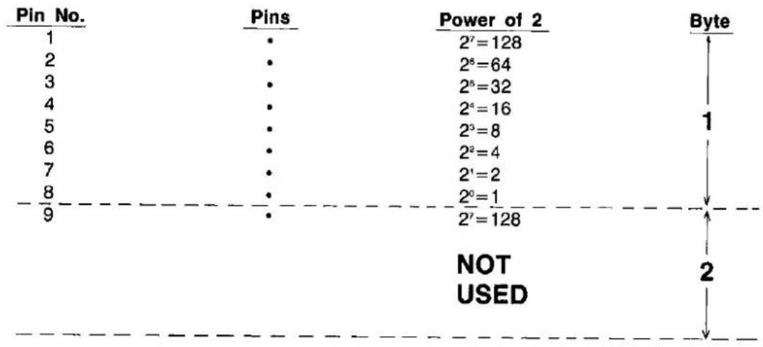
other
| Pin No. | Pins | Power of 2 | Byte | | :--- | :--- | :--- | :--- | | 1 | • | 2^7 = 128 | 1 | | 2 | • | 2^6 = 64 | | | 3 | • | 2^6 = 32 | | | 4 | • | 2^5 = 16 | | | 5 | • | 2^3 = 8 | | | 6 | • | 2^2 = 4 | | | 7 | • | 2^1 = 2 | | | 8 | • | 2^0 = 1 | | | 9 | • | 2^7 = 128 | NOT USED 2As an example, suppose you want to fire pins 1, 2, 5, 8 and 9 simultaneously. Then you determine the following two values:
Byte 1: Input Code=Pin 1 Code+Pin 2 Code+Pin 5 Code+Pin 8 Code
$$ = 2 ^ {7} + 2 ^ {6} + 2 ^ {3} + 2 ^ {0} $$
$$ = 1 2 8 + 6 4 + 8 + 1 $$
$$ = 2 0 1 $$
Byte 2: Input Code=Pin 9 Code
$$ = 2 ^ {7} $$
$$ = 1 2 8 $$
Thus, the two bytes for a single column of dots are entered as:
CHR\(201); CHR\(128);
Refer to the 9-pin standard density designation in Table 4.6. This setting is given by ESC+^+m+n1+n2, where m=0. Suppose you wish to print 100 columns of dots, where every column fires pins 1, 2, 5, 8 and 9 as above.
As in the 8-pin example on page 4-38, n_1 = 100 and n_2 = 0 . Our control code ESC +^ + m + n1 + n2 now translates into:
$$ \text { LPRINT } \quad \text { CHR } (2 7) + ^ {\prime \prime} ^ {\wedge}" + \text { CHR } (0) + \text { CHR } (1 0 0) + \text { CHR } (0); $$
If we incorporate this information into a program, we might have the following:
10 REM 9-PIN STANDARD DENSITY
20 WIDTH "LPT1:", 255
30 OPEN "LPT1:" AS #1
40 PRINT#1, CHR(27) + "^"+CHR(0) + CHR(100) + CHR(0);
50 FOR I=1 TO 100
60 PRINT#1, CHR(201) + CHR(128);
70 NEXT I
80 PRINT#1, CHR$(10);
90 CLOSE
100 END
Before proceeding with examples of each graphics control command, three important points are worth noting.
First, bit image graphics is automatically set to single direction (left to right) printing. This is done to ensure that dots are correctly aligned vertically.
Second, the graphics mode is released immediately following the printing of all bit image data. Printing will return to the text mode.
Third, any bit image data are not affected by MSB control commands.
STANDARD DENSITY GRAPHICS:
Sets standard density graphics mode (480 dots per line/60 dots per inch·(25.4 mm)).
Name: ESC + K + n1 + n2
Code: 27,75,n1,n2 DEC 18,4B,n1,n2 HEX
Input Format: LPRINT CHR\(27) + "K" + CHR\(n1) + CHR\$(n2);
Example: 10 REM STANDARD DENSITY GRAPHICS
20 WIDTH "LPT1:", 255
30 OPEN "LPT1:" AS #1
40 PRINT#1, "STANDARD DENSITY GRAPHICS"
50 PRINT#1, CHR$(10);
60 PRINT#1, CHR(27) + "K" + CHR(64) + CHR$(1);
70 FOR I = 1 TO 20
80 PRINT#1, CHR(1) + CHR(1) + CHR(3) + CHR(3);
90 PRINT#1, CHR(7) + CHR(7) + CHR(15) + CHR(15);
100 PRINT#1, CHR(31) + CHR(31) + CHR(63) + CHR(63);
110 PRINT#1, CHR(127) + CHR(127) + CHR(255) + CHR(255);
120 NEXT I
130 PRINT#1, CHR$(10);
140 CLOSE
150 END
STANDARD DENSITY GRAPHICS
DOUBLE DENSITY GRAPHICS:
Sets double density graphics mode (960 dots per line/120 dots per inch (25.4 mm)).
Name: ESC + L + n1 + n2
Code: 27,76,n₁,n₂ DEC 1B,4C,n₁,n₂ HEX
Input Format: LPRINT CHR\(27) + "L" + CHR\(n1) + CHR\$(n2);
Example: 10 REM DOUBLE DENSITY GRAPHICS
20 WIDTH "LPT1:", 255
30 OPEN "LPT1:" AS #1
40 PRINT#1, "DOUBLE DENSITY GRAPHICS"
50 PRINT#1, CHR$(10);
60 PRINT#1, CHR(27) + "L" + CHR(144) + CHR$(1);
70 FOR I=1 TO 25
80 PRINT#1, CHR(1) + CHR(1) + CHR(3) + CHR(3);
90 PRINT#1, CHR(7) + CHR(7) + CHR(15) + CHR(15);
100 PRINT#1, CHR(31) + CHR(31) + CHR(63) + CHR(63);
110 PRINT#1, CHR(127) + CHR(127) + CHR(255) + CHR(255);
120 NEXT I
130 PRINT#1, CHR$(10);
140 CLOSE
150 END
DOUBLE DENSITY GRAPHICS
DOUBLE SPEED, DOUBLE DENSITY GRAPHICS:
Sets double speed, double density graphics mode (960 dots per line/120 dots per inch (25.4 mm)).
Name: ESC + Y + n_1 + n_2
Code: 27,89,n1,n2 DEC 1B,59,n1,n2 HEX
Input Format: LPRINT CHR\(27) + "Y" + CHR\(n1) + CHR\$(n2);
Example: 10 REM DOUBLE SPEED, DOUBLE DENSITY GRAPHICS
20 WIDTH "LPT1:", 255
30 OPEN "LPT1:" AS #1
40 PRINT#1, "DOUBLE SPEED, DOUBLE DENSITY GRAPHICS"
50 PRINT#1, CHR$(10);
60 PRINT#1, CHR(27) + "Y" + CHR(144) + CHR$(1);
70 FOR I=1 TO 25
80 PRINT#1, CHR(1) + CHR(1) + CHR(3) + CHR(3);
90 PRINT#1, CHR(7) + CHR(7) + CHR(15) + CHR(15);
100 PRINT#1, CHR(31) + CHR(31) + CHR(63) + CHR(63);
110 PRINT#1, CHR(127) + CHR(127) + CHR(255) + CHR(255);
120 NEXT I
130 PRINT#1, CHR$(10);
140 CLOSE
150 END
DOUBLE SPEED, DOUBLE DENSITY GRAPHICS

Comment:
●Horizontally adjacent dots cannot be printed.
QUADRUPLE DENSITY GRAPHICS:
Sets quadruple density graphics mode (1920 dots per line/240 dots per inch (25.4 mm)).
Name: ESC + Z + n1 + n2
Code: 27,90,n1,n2 DEC 1B,5A,n1,n2 HEX
Input Format: LPRINT CHR\(27) + "Z" + CHR\(n1) + CHR\$(n2);
Example: 10 REM QUADRUPLE DENSITY GRAPHICS
20 WIDTH "LPT1:", 255
30 OPEN "LPT1:" AS #1
40 PRINT#1, "QUADRUPLE DENSITY GRAPHICS"
50 PRINT#1, CHR$(10);
60 PRINT#1, CHR(27) + "Z" + CHR(144) + CHR$(1);
70 FOR I = 1 TO 25
80 PRINT#1, CHR(1) + CHR(1) + CHR(3) + CHR(3);
90 PRINT#1, CHR(7) + CHR(7) + CHR(15) + CHR(15);
100 PRINT#1, CHR(31) + CHR(31) + CHR(63) + CHR(63);
110 PRINT#1, CHR(127) + CHR(127) + CHR(255) + CHR(255);
120 NEXT I
130 PRINT#1, CHR$(10);
140 CLOSE
150 END
QUADRUPLE DENSITY GRAPHICS

Comment:
● Horizontally adjacent dots cannot be printed.
8-PIN BIT IMAGE MODE SELECTION:
Selects one of eight 8-pin bit image graphic modes.
(Standard Mode only)
Name: ESC + x + m + n_1 + n_2 0 ≤ m ≤ 7
Code: 27,42,m,n1,n2 DEC 1B,2A,m,n1,n2 HEX
Input Format: LPRINT CHR\(27) + " * " + CHR\(m) + CHR\(n1) + CHR\(n2);
Example: 10 REM 8-PIN BIT IMAGE MODE SELECTION
20 WIDTH "LPT1:", 255
30 OPEN "LPT1:" AS #1
40 FOR M=0 TO 7
50 PRINT#1, "IMAGE MODE ="; M
60 PRINT#1, CHR$(10);
70 PRINT#1, CHR(27) + "*"+CHR(M)+CHR(200)+CHR(O);
80 FOR I=1 TO 25
90 PRINT#1, STRING(4, CHR(15));
100 PRINT#1, STRING(4, CHR(240));
110 NEXT I
120 PRINT#1, CHR$(10);
130 NEXT M
140 PRINT#1, CHR$(10);
150 CLOSE
160 END

IMAGE MODE = 0

IMAGE MODE = 1

IMAGE MODE = 2

IMAGE MODE = 3

IMAGE MODE = 4

IMAGE MODE = 5

IMAGE MODE = 6

IMAGE MODE = 7
Comments:
- Table 4.7 illustrates the various modes based upon the values of m.
| Value of m | Mode | Dot Density |
| 0 | Standard density | 480 dpl/ 60 dpi |
| 1 | Double density | 960 dpl/120 dpi |
| 2 | Double speed, double density | 960 dpl/120 dpi |
| 3 | Quadruple density | 1920 dpl/240 dpi |
| 4 | 640 dot density | 640 dpl/ 80 dpi |
| 5 | 576 dot density | 576 dpl/ 72 dpi |
| 6 | 720 dot density | 720 dpl/ 90 dpi |
| 7 | 1152 dot density | 1152 dpl/144 dpi |
Table 4.7 Dot Density
- Both the vertical and horizontal dot pitches in the 576 dot density mode equal 1/72 inch (0.35 mm), thereby producing a 1:1 aspect ratio.
●The following settings are equivalent:
-ESC + K + n_1 + n_2 and ESC + * + 0 + n_1 + n_2
-ESC + L + n_1 + n_2 and ESC + * + 1 + n_1 + n_2
-ESC + Y + n_1 + n_2 and ESC + X + 2 + n_1 + n_2
—ESC+Z+n1+n2 and ESC+*+3+n1+n2
9-PIN BIT IMAGE MODE SELECTION:
(Standard Mode only)
Selects one of eight 9-pin bit image graphic modes.
Name:
$$ E S C + ^ {\wedge} + m + n _ {1} + n _ {2} $$
$$ 0 \leq m \leq 7 $$
Code:
$$ 2 7, 9 4, m, n _ {1}, n _ {2} \text { DEC } $$
$$ 1 8, 5 E, m, n _ {1}, n _ {2} \text { HEX } $$
Input Format: LPRINT CHR\(27) + " ^ " + CHR\(m) + CHR\(n.) + CHR\(n2);
Example:
10 REM 9-PIN BIT IMAGE MODE SELECTION
20 WIDTH "LPT1:", 255
30 OPEN "LPT1:" AS #1
40 FOR N=0 TO 7
50 PRINT#1, "IMAGE MODE =";N
60 PRINT#1, CHR$(10);
70 PRINT#1, CHR(27)+"^"+CHR(N)+CHR(180)+CHR(0);
80 FOR I=1 TO 10
90 PRINT#1, CHR(0)+CHR(128)+CHR(0)+CHR(128);
100 PRINT#1, CHR(1)+CHR(128)+CHR(1)+CHR(128);
110 PRINT#1, CHR(3)+CHR(128)+CHR(3)+CHR(128);
120 PRINT#1, CHR(7)+CHR(128)+CHR(7)+CHR(128);
130 PRINT#1, CHR(15)+CHR(128)+CHR(15)+CHR(128);
140 PRINT#1, CHR(31)+CHR(128)+CHR(31)+CHR(128);
150 PRINT#1, CHR(63)+CHR(128)+CHR(63)+CHR(128);
160 PRINT#1, CHR(127)+CHR(128)+CHR(127)+CHR(128);
170 PRINT#1, CHR(255)+CHR(128)+CHR(255)+CHR(128);
180 NEXT I
190 PRINT#1, CHR$(10);
200 NEXT N
210 PRINT#1, CHR$(10);
220 CLOSE
230 END
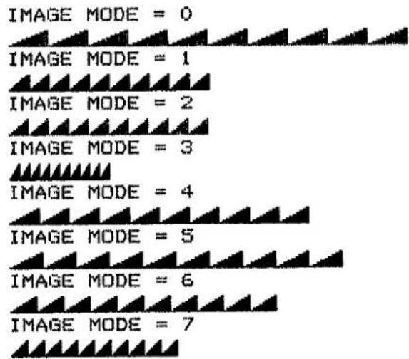
BIT IMAGE MODE REASSIGNMENT:
(Standard Mode only)
Reassigns bit image graphics mode density.
| Name: | ESC+?+n+m | n=75,76,89,90 |
| m=0,1,2,3,4,5,6,7 |
| Code: | 27,63,n,m DEC | 1B,3F,n,m,HEX |
Input Format: LPRINT CHR\(27) + “?” + CHR\(n) + CHR\$(m);
Example:
10 REM BIT IMAGE MODE REASSIGNMENT
20 WIDTH "LPT1:", 255
30 OPEN "LPT1:" AS #1
40 FOR L=1 TO 2
50 IF L=1 THEN PRINT#1, "NORMAL (ESC+K+n1+n2)"
60 IF L=2 THEN PRINT#1, "REASSIGN (ESC+K+n1+n2) TO QUAD. DENSITY"
70 PRINT#1, CHR$(10);
80 IF L=2 THEN PRINT#1, CHR(27)+?"?"+"K"+CHR(3);
90 PRINT#1, CHR(27)+"K"+CHR(0)+CHR$(1);
100 FOR I=1 TO 256
110 PRINT#1, CHR$(255);
120 NEXT I
130 PRINT#1, CHR(10); CHR(10);
140 NEXT L
150 CLOSE
160 END
NORMAL (ESC+K+n1+n2)
REASSIGN (ESC+K+n1+n2) TO QUAD. DENSITY
Comments:
- The value of “n” specifies the graphics mode which is to be reassigned:
    n=75: Reassign STANDARD DENSITY (ESC+K+n₁+n₂)
    n=76: Reassign DOUBLE DENSITY (ESC+L+n₁+n₂)
    n=89: Reassign DOUBLE SPEED, DOUBLE DENSITY (ESC+Y+n₁+n₂)
    n=90: Reassign QUADRUPLE DENSITY (ESC+Z+n₁+n₂)

- The value of “m” specifies the graphics mode to which the original is to be reassigned:
    m=0: Reassign to STANDARD DENSITY
    m=1: Reassign to DOUBLE DENSITY
    m=2: Reassign to DOUBLE SPEED, DOUBLE DENSITY
    m=3: Reassign to QUADRUPLE DENSITY
    m=4: Reassign to 640 DOTS PER LINE DENSITY
    m=5: Reassign to 576 DOTS PER LINE DENSITY
    m=6: Reassign to 720 DOTS PER LINE DENSITY
    m=7: Reassign to 1152 DOTS PER LINE DENSITY
- Refer to Table 4.6 on p.4-36 for details on the various bit image densities.
PAPER FEED CONTROL
Paper feed refers to either the specification of the amount of paper to be fed or the commands to actually cause the paper to be fed. Paper feed amount and execution are discussed below. Settings for page length, vertical tab positions, and skip perforation remain as initially set even if the paper feed amount is changed.
•PAPER FEED AMOUNT•
Table 4.8 lists the various control commands for paper feed.
| Line Pitch Size | Standard Mode | IBM Proprinter Mode |
| 18'' (3.2 mm) 772'' (2.47 mm) 16'' (4.2 mm) 772'' 1216'' | ESC+0ESC+1ESC+2ESC+A+nESC+3+n | ESC+0ESC+1'ESC+A+12 ^2 ESC+A+n, ESC+2ESC+3+nIf not set, default line spacing is 16'' . ^2 ESC+A+n must be followed by ESC+2. |
Table 4.8 Selection of Paper Feed Amount
1 / 8 INCH PAPER FEED:
Sets paper feed amount to 18 inch (3.2 mm).
Name: ESC+0
Code: 27,48 DEC 1B,30 HEX
Input Format: LPRINT CHR\$(27) + "0";
Example: 10 REM PAPER FEED AMOUNT=1/8 INCH
20 LPRINT "PAPER FEED AMOUNT = 1/8 INCH"
30 LPRINT CHR$(27)+"0";
40 FOR I=1 TO 4
50 LPRINT "____"
60 NEXT I
70 END
PAPER FEED AMOUNT = 1/8 INCH
Comment:
- ESC+0 sets 18 inch paper feed in all printer modes.
7/72 INCH PAPER FEED:
Sets paper feed amount to 772 inch (2.47 mm).
Name: ESC+1
Code: 27,49 DEC 1B,31 HEX
Input Format: LPRINT CHR\$(27) + "1";
Example: 10 REM PAPER FEED AMOUNT=7/72 INCH
20 LPRINT "PAPER FEED AMOUNT = 7/72 INCH"
30 LPRINT CHR$(27)+"1";
40 FOR I=1 TO 4
50 LPRINT "____"
60 NEXT I
70 END
PAPER FEED AMOUNT = 7/72 INCH
Comment:
- ESC+1 sets 7/72 inch paper feed in all printer modes.
16 INCH PAPER FEED:
Sets paper feed amount to 16 inch (4.2 mm).
Name: ESC+2
Code: 27,50 DEG 1B,32 HEX
Input Format: LPRINT CHR\$(27) + "2";
Example: 10 REM PAPER FEED AMOUNT=1/6 INCH
20 LPRINT "PAPER FEED AMOUNT = 1/6 INCH"
30 LPRINT CHR$(27)+"2";
40 FOR I=1 TO 4
50 LPRINT ""
60 NEXT I
70 END
PAPER FEED AMOUNT = 1/6 INCH
Comment:
- ESC+2 sets 18 inch paper feed in Standard Printer Mode only. Use ESC+A+n, n=12, to set 18 inch paper feed and use ESC+2 to activate the ESC+A+n setting in the IBM Proprinter mode. The IBM Proprinter mode defaults to 18 inch.
n/72 INCH PAPER FEED:
Sets programmable paper feed amount to 172 inch.
Name: ESC+A+n
Code: 27,65,n DEC 1B,41,n HEX
Input Format: LPRINT CHR\(27) + "A" + CHR\(n);
Example: 10 REM PAPER FEED AMOUNT=n/72 INCH
20 WIDTH "LPT1:",255
30 OPEN "LPT1:" AS #1
40 PRINT#1,"PAPER FEED AMOUNT = n/72 INCH"
50 FOR I=1 TO 20
60 PRINT#1,CHR(27)+"A"+CHR(I);
70 PRINT#1,"____"
80 PRINT#1,CHR$(10);
90 NEXT I
100 CLOSE
110 END
PAPER FEED AMOUNT = n/72 INCH
Comments:
- In the IBM Proprinter mode only, ESC+2 must be input after ESC+A+n for 172 inch paper feed to become effective.
- n 2 inch paper feed is valid for 0 ≤ n ≤ 85 .
n/216 INCH PAPER FEED:
Sets programmable paper feed amount to 1216 inch.
Name: ESC+3+n
Code: 27,51,n DEC 1B,33,n HEX
Input Format: LPRINT CHR\(27) + "3" + CHR\(n);
Example: 10 REM PAPER FEED AMOUNT=n/216 INCH
20 WIDTH "LPT1:", 255
30 OPEN "LFT1:" AS #1
40 PRINT#1, "PAPER FEED AMOUNT = n/216 INCH"
50 FOR I=1 TO 20
60 PRINT#1, CHR\(27) + "3" + CHR\(I);
70 PRINT#1,"
80 PRINT#1, CHR\$(10);
90 NEXT I
100 CLOSE
110 END
Comments:
- n / 216 inch paper feed is valid for 0 ≤ n ≤ 255 .
- ESC+3+n sets 12 16 programmable paper feed in all printer modes.
AUTOMATIC LINE FEED MODE:
(IBM Proprinter Mode only)
Automatically executes a Line Feed following a Carriage Return.
| Name: | Setting: | ESC+5+n | n=1,49,129,177 |
| Release: | ESC+5+m | m=0,48,128,176 |
| Code: | Setting: 27,53,n DEC | 1B,35,n HEX |
| Release: 27,53,m DEC | 1B,35,m HEX |
| Input Format: | Setting: | LPRINT CHR(27) + “5” + CHR(n); |
| Release: | LPRINT CHR(27) + “5” + CHR(m); |
| Example: | 10 REM AUTOMATIC LINE FEED MODE (for IBM PROPRINTER) |
| 20 WIDTH "LPT1:", 255 | |
| 30 OPEN "LPT1:" AS #1 | |
| 40 PRINT#1, CHR(27)+"5"+CHR(1); | |
| 50 FOR I=1 TO 3 | |
| 60 PRINT#1, "AUTO LINE FEED MODE ON"; CHR(13); | |
| 70 NEXT I | |
| 80 PRINT#1, CHR(27)+"5"+CHR(0); | |
| 90 FOR I=1 TO 3 | |
| 100 PRINT#1,"AUTO LINE FEED MODE OFF"; CHR(13); | |
| 110 NEXT I | |
| 120 CLOSE | |
| 130 END |
| AUTO | LINE | FEED | MODE | ON |
| AUTO | LINE | FEED | MODE | ON |
| AUTO | LINE | FEED | MODE | ON |
| AUTO | LINE | FEED | MODE | OFF |
Comments:
- DIP Switch 3 also controls the auto line feed function (refer to section 3.3). Setting this switch to the ON position is equivalent to executing the ESC+5+n command. Similarly, setting the switch to the OFF position is equivalent to executing the ESC+5+m command.
- Lines 20, 30, 120, and all PRINT# statements in the above sample BASIC program are necessary for those computers which automatically execute an LF following a CR.
- LF is tied to CR in this mode.
•PAPER FEED EXECUTION•
LINE FEED (LF):
Causes data in buffer to be printed and then executes a single line feed.
Name: LF
Code: 10 DEC 0A HEX
Input Format: LPRINT CHR\$(10);
Example: 10 REM LINE FEED 20 LPRINT "LINE"; CHR\$(10); "FEED" 30 END
LINE FEED
Comments:
- When the new line position falls within the perforation skip area, the paper advances to the next top of form position (when DIP switch 4 is ON).
- If there is no data, "space" data (ASCII 32), or blanks between HT print positions in the buffer, LF feeds the paper by only 1 line.
- The amount of spacing generated by LF is a function of the paper feed amount setting.
- LF code releases single-line double width printing set by SO.
- In the IBM Proprinter mode only, DIP switch 5 controls the Automatic CR function. When this switch is OFF, LF executes a single line feed. The carriage, however, does not return to the left margin position. When this switch is ON, a Carriage Return command (CR) is added to each Line Feed (LF).
FORM FEED (FF):
Feeds paper to next top of form position after first printing any data in the buffer.
Name: FF
Code: 12 DEC 0C HEX
Input Format: LPRINT CHR\$(12);
Example: (See ESC+C+0+n or ESC+C+n)
Comments:
- FF releases single-line double width printing set by SO (see page 4-26).
- Amount of form feed depends upon page length set by the page length control command.
n/216 INCH PAPER FEED:
Prints out the data in the print buffer and feeds the paper 12 inch.
Name: ESC+J+n
Code: 27,74,n DEC 1B,4A,n HEX
Input Format: LPRINT CHR\(27) + "J" + CHR\(n);
Example: 10 REM SINGLE-LINE PROGRAMMABLE PAPER FEED 20 LPRINT " SINGLE-LINE PROGRAMMABLE PAPER FEED"; 30 LPRINT CHR\(27)+"J"+CHR\(108); 40 LPRINT "OF ONE-HALF INCH" 50 FOR I=1 TO 3 60 LPRINT "NORMAL PAPER FEED" 70 NEXT I 80 END
SINGLE-LINE PROGRAMMABLE PAPER FEED
OF ONE-HALF INCH
NORMAL PAPER FEED
NORMAL PAPER FEED
NORMAL PAPER FEED
Comments:
- In the IBM Proprinter mode only, when DIP switch 5 (Automatic CR) is ON, Carriage Return command (CR) is added automatically to this command.
- Single-line, 1216 inch paper feed is valid for 0 ≤ n ≤ 255 .
- This command sets the paper feed for ONE line only. Subsequent paper feed returns to previous setting. However, the carriage does not return to the left margin position. Instead, printing of next line begins where previous printing left off.
- This command does not release single-line double width printing.
n-LINE PAPER FEED:
(Standard Mode only)
Feeds the paper "n" lines after printing data in the buffer.
Name: ESC+f+1+n
Code: 27,102,1,n DEC 1B,66,01,n HEX
Input Format: LPRINT CHR\(27) + "f" + CHR\(1) + CHR\$(n);
Example: 10 REM n-LINE PAPER FEED 20 LPRINT "PAPER FEED OF"; 30 LPRINT CHR\(27) + "f" + CHR\(1) + CHR\$(6); 40 LPRINT "6 LINES" 50 END
PAPER FEED OF
6 LINES
Comments:
- ESC+1+1+n uses the current paper feed amount and printing continues in the very next column where previous printing ended.
- The value of n must be in the range 0 ≤ n ≤ 127 . If n ≥ 128 , the paper is fed n - 128 lines.
- Programmable n-line paper feed does not release double width printing.
PAGE FORMAT CONTROL
Page format commands will enable you to design the layout of your printed page. Such commands include page length, margin alignment, centering, justification and skip perforation commands.
PAGE LENGTH (INCHES):
Sets page length in inches.
Name: ESC+C+0+n
Code: 27,67,0,n DEC 1B,43,00,n HEX
Input Format: LPRINT CHR\(27) + "C" + CHR\(0) + CHR\$(n);
Example: 10 REM PAGE LENGTH (INCHES)
20 LPRINT CHR(27) + "C" + CHR(0) + CHR$(1);
30 LPRINT "THIS PAGE IS 1 INCH LONG";
40 LPRINT CHR$(12);
50 LPRINT CHR(27) + "C" + CHR(0) + CHR$(2);
60 LPRINT "THIS PAGE IS 2 INCHES LONG";
70 LPRINT CHR$(12);
80 LPRINT "NEXT PAGE"
90 END
THIS PAGE IS 1 INCH LONG
THIS PAGE IS 2 INCHES LONG
NEXT PAGE
Comments:
- Upon receipt of ESC+C+0+n, the present line position becomes the top of page position.
●The value of n must be in the range 1≤n≤22. - ESC+C+0+n releases the VT, VFU and skip perforation settings.
●The page length does not change even if the paper feed amount is changed. - The terms "form" and "page" are interchangeable.
PAGE LENGTH (LINES):
Sets page length in number of lines.
Name: ESC+C+n
Code: 27,67,n DEC 1B,43,n HEX
Input Format: LPRINT CHR\(27) + "C" + CHR\(n);
Example: 10 REM PAGE LENGTH (LINES) 20 LPRINT CHR\(27) + "C" + CHR\(3); 30 LPRINT "THIS PAGE IS 3 LINES LONG" 40 LPRINT CHR\$(12); 50 LPRINT CHR\(27) + "C" + CHR\(5); 60 LPRINT "THIS PAGE IS 5 LINES LONG" 70 LPRINT CHR\$(12); 80 LPRINT "NEXT PAGE" 90 END
THIS PAGE IS 3 LINES LONG
THIS PAGE IS 5 LINES LONG
NEXT PAGE
Comments:
- Upon receipt of ESC+C+n, the present line position becomes the top of page position.
- The value of n must be in the range 1 ≤ n ≤ 127 . If n = 0 , page length returns to the inch designation.
- ESC+C+n releases the VT, VFU and skip perforation settings.
- The page length does not change even if the paper feed amount is changed.
- The terms "form" and "page" are interchangeable.
TOP OF FORM:
(IBM Proprinter Mode only)
Sets top of form.
Name: ESC+4
Code: 27,52 DEC 1B,34 HEX
Input Format: LPRINT CHR\$(27) + "4";
Example: 10 REM TOP OF FORM SET
20 LPRINT CHR\(27)+"C"+CHR\(4);
30 LPRINT "----TOP OF FORM POSITION----"; CHR\$(12);
40 LPRINT "---NEXT PAGE TOP OF FORM POSITION---";
50 LPRINT CHR\$(10)
60 LPRINT CHR\$(27)+"4";
70 LPRINT "---NEW TOP OF FORM POSITION---"; CHR\$(12);
80 LPRINT "----NEXT PAGE TOP OF FORM POSITION----"
90 END
---TOP OF FORM POSITION---
---NEXT PAGE TOP OF FORM POSITION---
---NEW TOP OF FORM POSITION---
---NEXT PAGE TOP OF FORM POSITION---
Comment:
●This command sets the current paper position as the top of form.
LEFT MARGIN:
(Standard Mode only)
Sets position of left margin.
Name: ESC+1+n
Code: 27,108,n DEC 1B,6C,n HEX
Input Format: LPRINT CHR\(27) + "I" + CHR\(n);
Example: 10 REM LEFT MARGIN SETTING
20 FOR I=1 TO 5
30 LPRINT "0123456789";
40 NEXT I
50 LPRINT CHR$(10);
60 LPRINT CHR(27)+"1"+CHR(10);
70 LPRINT "LEFT MARGIN 10"
80 LPRINT CHR(27)+"1"+CHR(20);
90 LPRINT "LEFT MARGIN 20"
100 END
01234567890123456789012345678901234567890123456789
LEFT MARGIN 10
LEFT MARGIN 20
Comments:
- If the value of n exceeds the right margin value, ESC + 1 + n is ineffective and the left margin does not change.
- Setting the left margin position clears all data in the print buffer.
- In proportional spacing, the left margin is set with pica pitch.
- Once the left margin position is set, a change in the character mode will not alter this left margin setting.
RIGHT MARGIN:
(Standard Mode only)
Sets position of right margin.
Name: ESC+Q+n
Code: 27,81,n DEC 1B,51,n HEX
Input Format: LPRINT CHR\(27) + "Q" + CHR\(n);
Example: 10 REM RIGHT MARGIN SETTING
20 FOR I=1 TO 5
30 LPRINT "1234567890";
40 NEXT I
50 LPRINT CHR$(10)
60 LPRINT CHR(27)+"Q"+CHR(40);
70 LPRINT "RIGHT MARGIN 40"
80 FOR I=1 TO 5
90 LPRINT "1234567890";
100 NEXT I
110 LPRINT CHR$(10)
120 LPRINT CHR(27)+"Q"+CHR(30);
130 LPRINT "RIGHT MARGIN 30"
140 FOR I=1 TO 5
150 LPRINT "1234567890";
160 NEXT I
170 LPRINT CHR$(10)
180 END
12345678901234567890123456789012345678901234567890
RIGHT MARGIN 40
1234567890123456789012345678901234567890
1234567890
RIGHT MARGIN 30
123456789012345678901234567890
12345678901234567890
Comments:
●Permissible values of "n" are given below.
Pica print 2≤n≤80
Compressed print 4≤n≤137
Double Width print 1≤n≤40
Double Width/Compressed print 2≤n≤68
●Any designation to the left of the left margin position is ignored.
- Setting the right margin clears all data in the buffer.
- In proportional spacing, the right margin is set with pica pitch.
- Once the right margin position is set, a change in the character mode will not alter this right margin setting.
MARGIN SET:
(IBM Proprinter Mode only)
Sets positions of left and right margins.
Name: ESC + X + n1 + n2
Code: 27,88, n_1,n_2 DEC 1B,58, n_1,n_2 HEX
Input Format: LPRINT CHR\(27) + "X" + CHR\(n1) + CHR\$(n2);
Example: 10 REM LEFT/RIGHT MARGIN SETTING
20 FOR I=1 TO 5
30 LPRINT "1234567890";
40 NEXT I
50 LPRINT CHR\$(10)
60 LPRINT "LEFT MARGIN=10 : RIGHT MARGIN=40"
70 LPRINT CHR\(27) + "X" + CHR\(10) + CHR\$(40);
80 FOR I=1 TO 5
90 LPRINT "1234567890";
100 NEXT I
110 LPRINT CHR\$(10)
120 END
12345678901234567890123456789012345678901234567890
LEFT MARGIN=10 : RIGHT MARGIN=40
1234567890123456789012345678901
2345678901234567890
Comments:
- The left margin column is set to n_1 in the current width, and the right margin column is set to n_2 .
- Permissible values of “ n_2 ” are given below.
Pica print
2 ≤ n_2 ≤ 80
Compressed print
4 ≤ n_2 ≤ 137
- Any designation to the left of the left margin position is ignored.
- Setting the margin clears all data in the buffer.
- Once the margin position is set, a change in the character mode will not alter this margin setting.
- When n_1 = 0 , the left margin does not change. When n_e = 0 , the right margin does not change.
LEFT ALIGNMENT:
(Standard Mode only)
Sets print alignment at the left margin.
Name: ESC+a+0
Code: 27,97,0 DEC 1B,61,00 HEX
Input Format: LPRINT CHR\(27) + "a" + CHR\(0);
Example: (See RIGHT ALIGNMENT)
Comments:
●This command clears the ESC+a+1, ESC+a+2 and ESC+a+3 settings.
●The printer defaults to this setting.
●48,128 and 176 can also be used in place of 0.
AUTO CENTERING:
(Standard Mode only)
Enables automatic centering of a print line between the left and right margins.
Name: ESC+a+1
Code: 27,97,1 DEC 1B,61,01 HEX
Input Format: LPRINT CHR\(27) + "a" + CHR\(1);
Example: (See RIGHT ALIGNMENT)
Comments:
- This command clears the ESC+a+0, ESC+a+2 and ESC+a+3 settings.
-49,129 and 177 can also be used in place of 1.
RIGHT ALIGNMENT:
(Standard Mode only)
Sets print alignment at the right margin.
Name: ESC+a+2
Code: 27,97,2 DEC 1B,61,02 HEX
Input Format: LPRINT CHR\(27) + "a" + CHR\(2);
Example: 10 REM AUTO CENTERING, RIGHT ALIGNMENT, LEFT ALIGNMENT
20 LPRINT CHR(27) + "Q" + CHR(40);
30 FOR I = 1 TO 4: LPRINT "1234567890"; : NEXT I
40 LPRINT
50 LPRINT CHR(27) + "a" + CHR(1);
60 LPRINT "AUTO CENTERING"
70 LPRINT "THIS IS SAMPLE TEXT."
80 LPRINT CHR(27) + "a" + CHR(2);
90 LPRINT "RIGHT ALIGNMENT"
100 LPRINT "THIS IS SAMPLE TEXT."
110 LPRINT CHR(27) + "a" + CHR(0);
120 LPRINT "LEFT ALIGNMENT"
130 LPRINT "THIS IS SAMPLE TEXT."
140 END
1234567890123456789012345678901234567890
AUTO CENTERING
THIS IS SAMPLE TEXT.
RIGHT ALIGNMENT
THIS IS SAMPLE TEXT.
LEFT ALIGNMENT
THIS IS SAMPLE TEXT.
Comments:
●This command clears the ESC+a+0, ESC+a+1 and ESC+a+3 settings.
●50,130 and 178 can also be used in place of 2.
AUTO JUSTIFICATION:
(Standard Mode only)
Sets automatic justification of a print line between the left and right margins.
Name: ESC+a+3
Code: 27,97,3 DEC 1B,61,03 HEX
Input Format: LPRINT CHR\(27) + "a" + CHR\(3);
Example:
10 REM AUTO JUSTIFICATION
20 LPRINT CHR(27)+"a"+CHR(3);
30 LPRINT CHR(27)+"Q"+CHR(40);
40 FOR I=0 TO 2
50 IF I=0 THEN LPRINT CHR$(27)+"P";"(DRAFT)"
60 IF I=1 THEN LPRINT CHR$(27)+"n";"(NLQ)"
70 IF I=2 THEN LPRINT CHR(27)+"p"+CHR(1);"(NLQ-PROPORTIONAL SPACING)"
80 LPRINT "SAMPLE TEXT FOR AUTO JUSTIFICATION"
90 LPRINT "THE QUICK BROWN FOX JUMPED OVER THE LAZY DOG"
100 LPRINT "This printer has a variety of features for WORD PROCESSING."
110 LPRINT CHR$(10);
120 NEXT I
130 END
(DRAFT)
SAMPLE TEXT FOR AUTO JUSTIFICATION THE QUICK BROWN FOX JUMPED OVER THE LAZY DOG This printer has a variety of features for WORD PROCESSING.
(NLQ)
SAMPLE TEXT FOR AUTO JUSTIFICATION THE QUICK BROWN FOX JUMPED OVER THE LAZY DOG This printer has a variety of features for WORD PROCESSING.
(NLQ-PROPORTIONAL SPACING)
SAMPLE TEXT FOR AUTO JUSTIFICATION THE QUICK BROWN FOX JUMPED OVER THE LAZY DOG This printer has a variety of features for WORD PROCESSING.
Comments:
- Printing is executed upon receipt of print execution commands (CR,LF,FF,etc.).
- BS and DEL are ineffective in auto justification mode.
- When the last character of a line is a period (.), auto justification is not executed.
●Auto justification is executed when data exceeds right margin and upon receipt of print execution commands (CR, LF, FF, etc.). - Too small number of or too many characters may not be justified.
- This command clears the ESC+a+0, ESC+a+1 and ESC+a+2 settings.
-51, 131 and 179 can also be used in place of 3.
SKIP PERFORATION:
Sets skip-over perforation.
| Name: | Setting: | ESC+N+n |
| Release: | ESC+O |
| Code: | Setting: 27,78,n DEC | 1B,4E,n HEX |
| Release: 27,79 DEC | 1B,4F HEX |
| Input Format: Setting: LPRINT CHR(27) + "N" + CHR(n) ;Release: LPRINT CHR$(27) + "O" ; |
Example: 10 REM SKIP PERFORATION
20 LPRINT CHR(27)+"C"+CHR(6);
30 LPRINT CHR(27)+"N"+CHR(3);
40 FOR I=1 TO 3
50 LPRINT "PAGE LENGTH SET TO 6 LINES - SKIP 3 LINES FROM PERF."
60 NEXT I
70 LPRINT CHR$(27)+"0";
80 FOR I=1 TO 7
90 LPRINT "SKIP PERFORATION IS CANCELLED"
100 NEXT I
110 END
PAGE LENGTH SET TO 6 LINES - SKIP 3 LINES FROM PERF.
PAGE LENGTH SET TO 6 LINES - SKIP 3 LINES FROM PERF.
PAGE LENGTH SET TO 6 LINES - SKIP 3 LINES FROM PERF.
SKIP PERFORATION IS CANCELLED
SKIP PERFORATION IS CANCELLED
SKIP PERFORATION IS CANCELLED
SKIP PERFORATION IS CANCELLED
SKIP PERFORATION IS CANCELLED
Comments:
- The value of n specifies the number of lines (or n times the current line spacing amount) to be skipped at the bottom of the page.
- This command is effective only for 1 ≤ n ≤ 127 . If n ≥ 128 , the value is processed as n - 128 .
- The skip perforation amount does not change even if the paper feed amount is changed following a skip perforation designation.
- The skip perforation setting is released upon receipt of the page length designation command.
- If DIP switch 4 is set to ON, the skip perforation amount is set to 1 inch (25.4 mm). If DIP switch 4 is set to OFF, skip perforation is not executed unless specified by ESC+N+n.
TABULATION
Tabulation can be extremely important in the production of documents where items must be printed at locations other than the standard margin settings. The printing of tables, for example, may require substantial use of tabulation ("tabs"). The control commands which follow pertain to either horizontal or vertical tabs. For either horizontal or vertical tabs, we shall discuss commands which set and commands which execute tabs.
• Horizontal •
HORIZONTAL TAB STOP SETTING:
Sets horizontal tabulations specified values.
Name: Setting: ESC + D + n_1 + n_2 + + n_k + 0
Release: ESC+D+0
Code: Setting: 27,68,n1,n2,...,n4,0 DEC 1B,44,n1,n2,...,nx,00 HEX
Release: 27,68,0 DEC 1B,44,00 HEX
Input Format: Setting: LPRINT CHR\(27) + "D" + CHR\(n1) + CHR\(n2) + ... + CHR\(n_n) + CHR\$(0);
Release: LPRINT CHR\(27) + "D" + CHR\(0);
Example: (See HT, example 1, on page 4-67)
Comments:
●Horizontal tabs are set from the left margin position.
- Horizontal tabs must be designated such that n_1 < n_2 < < n_n .
●A maximum of 32 tabs may be set on a single line.
- ESC + D + n_1 + n_2 + +n_k + 0 sets horizontal tab stops. The HT command on page 4-67 executes the tab designation.
- In proportional spacing, horizontal tabs are set with pica pitch.
- If the character pitch is altered after designating horizontal tabs, the tab positions do not change.
- When the left margin is changed, horizontal tabs default to every 8 columns, beginning with the new left margin setting (Standard Mode only).
- When the margin is changed, horizontal tabs will be moved according new left margin setting. (IBM Proprinter Mode only)
HORIZONTAL TAB UNIT SETTING:
(Standard Mode only)
Sets horizontal tabulation every "n" positions, beginning at the left margin.
Name: ESC+e+0+n
Code: 27,101,0,n DEC 1B,65,00,n HEX
Input Format: LPRINT CHR\(27) + "e" + CHR\(0) + CHR\$(n);
Example: (See HT, example 2, on page 4-67)
Comments:
●The HT unit setting is released when n=0 (ESC+e+0+0).
- HT is set every 8 columns in the default status.
- ESC+e+0+n sets horizontal tab units. The HT command on page 4-67 executes this tab designation.
HORIZONTAL TAB EXECUTION:
Executes the horizontal TAB as designated by ESC+D+n1+n2+...+nx+0, ESC+e+0+n
Name: HT
Code: 9 DEC 09 HEX
Input Format: LPRINT CHR\$(9);
Example 1: 10 REM HORIZONTAL TAB SETTING/EXECUTION/RELEASE
20 LPRINT "HT SETTING"
30 FOR I=1 TO 5
40 LPRINT "0123456789";
50 NEXT I
60 LPRINT CHR$(10);
70 LPRINT CHR$(27)+"D";
80 LPRINT CHR(1)+CHR(8)+CHR(20)+CHR(30)+CHR(45)+CHR(0);
90 FOR I=1 TO 5
100 LPRINT CHR(9);"HT";CHR(48+I);
110 NEXT I
120 LPRINT CHR$(10);
130 LPRINT "HT RELEASE"
140 LPRINT CHR(27)+"D"+CHR(0);
150 FOR I=1 TO 5
160 LPRINT CHR(9);"HT";CHR(48+I);
170 NEXT I
180 LPRINT CHR$(10);
190 END

HT SETTING
01234567890123456789012345678901234567890123456789
HT1 HT2 HT3 HT4 HT5
HT RELEASE
HT1HT2HT3HT4HT5
(The Example 1 program is executed in Standard printer mode. In the IBM Proprinter mode, horizontal tab positions are shifted one character to the left.)
Example 2: 10 REM HT UNIT SETTING/EXECUTION
(Standard 20 FOR I=1 TO 5
mode only) 30 LPRINT "0123456789";
40 NEXT I
50 LPRINT CHR\$(10);
60 LPRINT CHR\(27) + "e" + CHR\(0) + CHR\$(8);
70 LPRINT CHR\$(9); "TAB";
BO LPRINT CHR\(9); CHR\(9); "TAB";
90 LPRINT CHR\(9); CHR\(9); CHR\$(9); "TAB"
100 END
01234567890123456789012345678901234567890123456789
TAB TAB TAB
Comments:
- If the value of the horizontal TAB is less than the present column position, that HT is ignored.
- If the value of the horizontal TAB exceeds the maximum printing width, all data within correct printing range will be printed according to the HT setting(s). A single line feed is executed.
- When in underline mode, the blank spaces between consecutive HT print positions are not underlined.
- When the printer is powered up, TAB is automatically set every 8 characters.
• Vertical •
VERTICAL TAB STOP SETTING:
Sets vertical tabulation to specified values.
Name: Setting: ESC + B + n_1 + n_2 + + n_x + 0
Release: ESC+B+0
Code: Setting: 27,66,n1,n2,...,nx,0 DEC 1B,42,n1,n2,...,nx,00 HEX
Release: 27,66,0 DEC 1B,42,00 HEX
Input Format: Setting: LPRINT CHR\(27) + "B" + CHR\(n1) + CHR\(n2) + ... + CHR\(n*) + CHR\$(0);
Release: LPRINT CHR\(27) + "B" + CHR\(0);
Example: (See VT, example 1, on page 4-69)
Comments:
- VT is set from the top of page position.
- Vertical tabs must be designated such that n_1 < n_2 < < n_n .
●A maximum of 16 tabs may be set (in Standard mode).
●A maximum of 64 tabs may be set (in IBM Proprinter mode). - ESC + B + n_1 + n_2 + + n_n + 0 sets vertical tab stops. The VT command on page 4-69 executes the tab designation.
- If the paper feed amount is changed after a VT designation, the VT positions remain as initially set.
- VT setting is released by page length designation commands.
VERTICAL TAB UNIT SETTING:
(Standard Mode only)
Sets vertical tabulation every "n" lines, beginning at top of page.
Name: ESC+e+1+n
Code: 27,101,1,n DEC 1B,65,01,n HEX
Input Format: LPRINT CHR\(27) + "e" + CHR\(1) + CHR\$(n);
Example: (See VT, example 2, on page 4-70)
Comments:
- The VT unit setting is released when n = 1 (ESC+e+1+1).
- The maximum length for a VT unit is the page length, and when a VT unit designation exceeds the page length, the setting is ignored.
- If the paper feed amount is changed after a VT unit designation, the VT unit remains as initially set.
- When n = 0 , data is printed, but the paper is not fed.
- The VT unit setting is released by page length designation command.
- In the IBM Proprinter mode, when DIP switch 5 is OFF, VT executes paper feed to next vertical tab position, however, the carriage does not return to the left margin position. When this switch is ON, a Carriage Return command (CR) is added to each VT.
VERTICAL TAB EXECUTION:
Executes the vertical TAB as designated by ESC+B+n_1+n_2++n_x+0 , ESC+b+m+n_1+n_2++n_x+0 , or ESC+e+1+n .
Name: VT
Code: 11 DEC OB HEX
Input Format: LPRINT CHR\$(11);
Example 1: 10 REM VERTICAL TAB SETTING/EXECUTION/RELEASE
20 LPRINT "THIS PAGE IS 10 LINES LONG"
30 LPRINT CHR(27) + "C" + CHR(10);
40 LPRINT CHR(27) + "B" + CHR(3) + CHR(7) + CHR(0);
50 LPRINT "1ST LINE"; CHR$(11);
60 LPRINT "3RD LINE"; CHR$(11);
70 LPRINT "7TH LINE"; CHR$(12);
80 LPRINT CHR(27) + "B" + CHR(0);
90 LPRINT "1ST LINE"; CHR$(11);
100 LPRINT "3RD LINE"; CHR$(11);
110 LPRINT "7TH LINE"
120 END
THIS PAGE IS 10 LINES LONG 1ST LINE
3RD LINE
7TH LINE
1ST LINE 3RD LINE 7TH LINE
( The Example 1 program is executed in Standard printer mode. In IBM Proprinter mode, vertical tab position is shifted one line up.
Example 2: (See next page)
Example 2: 10 REM VT UNIT SETTING/EXECUTION
(Standard mode only)
20 LPRINT "THIS PAGE IS 20 LINES LONG"
30 LPRINT CHR(27) + "C" + CHR(20);
40 LPRINT CHR(27) + "e" + CHR(1) + CHR$(6);
50 LPRINT "1ST LINE"; CHR$(11);
60 LPRINT "7TH LINE"; CHR$(11);
70 LPRINT "13TH LINE"; CHR$(11);
80 LPRINT "19TH LINE"; CHR$(12);
90 LPRINT "1ST LINE (NEXT PAGE)"
100 END
THIS PAGE IS 20 LINES LONG 1ST LINE
7TH LINE
13TH LINE
19TH LINE
1ST LINE (NEXT PAGE)
Comments:
- When TABs are set with VT or VFU setting command and when there is no tab setting on a position exceeding present line, data is printed out and paper is fed to the next top of page position (same as FF) (Standard Mode only).
- When TABs are set with VT setting command and there is no tab setting on a position exceeding present line, data is printed out and advances the paper one line (same as LF) (IBM Proprinter mode only).
- When vertical TAB has not been set by ESC + B + n_1 + n_2 + + n_x + 0 , execution of VT causes data in the buffer to be printed and advances the paper one line (same function as LF).
VFU CHANNEL SELECTION:
(Standard Mode only)
Selects one of eight channels in the Vertical Format Unit (VFU).
Name: ESC+/+n 0≤n≤7
Code: 27,47,n DEC 1B,2F,n HEX
Input Format: LPRINT CHR\(27) + “/” + CHR\(n);
Example: (See VFU SETTING, pages 4-71, 4-72)
Comments:
- The value of n must be in the range 0 ≤ n ≤ 7 and selects one of eight channels (0-7).
- Channel 0 is the default setting.
VFU SETTING:
(Standard Mode only)
Sets the tab position of each channel in the VFU (Vertical Format Unit).
Name: Setting: ESC+b+m+n₁+n₂+...+nₓ+0 0≤m≤7, 1≤x≤16 Release: ESC+b+m+0
Code: Setting: 27,98,m,n1,n2,...,nx,0 DEC 1B,62,m,n1,n2,...,nx,00 HEX Release: 27,98,m,0 DEC 1B,62,m,00 HEX
Input Format: Setting: LPRINT CHR\(27) + "b" + CHR\(m) + CHR\(n1) + CHR\(n2) + ... + CHR\(nx) + CHR\(0); Release: LPRINT CHR\(27) + "b" + CHR\(m) + CHR\$(0);
Example: 10 REM VFU CHANNEL SELECTION
20 REM SET PAGE LENGTH TO 17 LINES
30 LPRINT CHR(27) + "C" + CHR(14);
40 REM VFU CHANNEL 1
50 LPRINT CHR(27) + "b" + CHR(1);
60 LPRINT CHR(3) + CHR(6) + CHR$(0);
70 REM VFU CHANNEL 2
80 LPRINT CHR(27) + "b" + CHR(2);
90 LPRINT CHR(4) + CHR(8) + CHR$(0);
100 REM VFU CHANNEL 3
110 LPRINT CHR(27) + "b" + CHR(3);
120 LPRINT CHR(5) + CHR(10) + CHR$(0);
130 REM EXECUTE EACH VFU CHANNEL
140 FOR N=1 TO 3
150 LPRINT "***** THIS LINE IS 'TOP OF PAGE' *****"
160 LPRINT CHR(27) + "/"+CHR(N);
170 FOR I=1 TO 2
180 LPRINT CHR$(11); "THIS IS VERTICAL TAB CHANNEL;"; N
190 NEXT I
200 LPRINT CHR$(12);
210 NEXT N
220 END
***** THIS LINE IS 'TOP OF PAGE' *****
THIS IS VERTICAL TAB CHANNEL: 1
THIS IS VERTICAL TAB CHANNEL: 1
***** THIS LINE IS 'TOP OF PAGE' *****
THIS IS VERTICAL TAB CHANNEL: 2
THIS IS VERTICAL TAB CHANNEL: 2
***** THIS LINE IS 'TOP OF PAGE' *****
THIS IS VERTICAL TAB CHANNEL: 3
THIS IS VERTICAL TAB CHANNEL: 3
Comments:
- The VFU has eight channels. A maximum of 16 vertical tabs can be set by each channel.
- The VFU is valid for 0 ≤ m ≤ 7 and selects one channel based on the value of "m".
- Any VFU setting exceeding the page length is ineffective.
- To operate the VFU, input the VT code (11 _csc ) after selecting the channel via VFU channel selection command (ESC+/+n).
- The VFU position does not change even if paper feed amount is altered after VFU setting.
- The VFU setting is released by the page length designation commands.
- The vertical tab specified with ESC + B + n_1 + n_2 + + n_x + 0 is set to VFU channel 0.
ALL TAB INITIAL CLEAR:
Sets all tabs to power ON settings.
(IBM Proprinter Mode only)
Name: ESC+R
Code: 27,82 DEC 1B,52 HEX
Input Format: LPRINT CHR\$(27) + "R";
Example: 10 REM ALL TAB INITIAL CLEAR
20 WIDTH "LPT1:", 255
30 OPEN "LPT1:" AS #1
40 FOR I=1 TO 5
50 PRINT#1, "1234567890";
60 NEXT I
70 PRINT#1, CHR$(10)
80 PRINT#1, CHR$(27) + "4";
90 PRINT#1, CHR(27) + "D" + CHR(5) + CHR(15) + CHR(30) + CHR$(0);
100 PRINT#1, CHR(27) + "B" + CHR(2) + CHR(5) + CHR(8) + CHR$(0);
110 FOR I=1 TO 3
120 PRINT#1, CHR(13); CHR(11);
130 FOR J=1 TO 3
140 PRINT#1, CHR$(9); "H";
150 NEXT J
160 PRINT#1, CHR$(10)
170 NEXT I
180 PRINT#1, CHR$(27) + "R";
190 PRINT#1, CHR$(27) + "4";
200 PRINT#1, "(ALL TAB CLEAR )"; CHR$(10)
210 FOR I=1 TO 3
220 FOR J=1 TO 3
230 PRINT#1, CHR$(9); "H";
240 NEXT J
250 PRINT#1, CHR(13); CHR(11);
260 NEXT I
270 END
12345678901234567890123456789012345678901234567890
H H H
H H H
H H H ( ALL TAB CLEAR ) H H H H H H H H H
Comment:
- This command sets horizontal tabs at every 8 position and clears all vertical tabs.
CARRIAGE CONTROL
Carriage control commands enable you to control the amount of movement, the direction of movement or the speed of the carriage.
BACKSPACE:
Prints data in buffer and backspaces one space before printing next character.
Name: BS
Code: 8 DEG 08 HEX
Input Format: LPRINT CHR\$(8);
Example: 10 REM UNDERLINE BY BACKSPACING
20 LPRINT "ABCDE";
30 FOR I=1 TO 5
40 LPRINT CHR\$(B);
50 NEXT I
60 LPRINT "____"
70 END
ABCDE
Comments:
- Since BS backspaces the width of a character, the backspacing amount will depend upon the character mode set when the BS code was received.
- See Underlining, example 2, page 4-28.
CARRIAGE RETURN:
Prints all data in buffer.
Name: CR
Code: 13 DEC 0D HEX
Input Format: LPRINT CHR\$(13);
Example: 10 REM CARRIAGE RETURN
20 LPRINT "ABCDE";
30 LPRINT "FGHIJ";
40 LPRINT "KLMNO";
50 REM NOW ADD CARRIAGE RETURN
60 LPRINT CHR\$(13);
70 LPRINT "PQRST"
80 END
ABCDEFGHIJKLMNOPQRSTUVWXYZ
FQRST
Comments:
- Certain computers issue an automatic line feed with a carriage return. Check your computer manual for details.
- When DIP switch 3 is ON the paper is fed automatically (a LF is executed automatically) whenever a CR code is executed.
HOME PRINT HEAD:
(Standard Mode only)
Causes print head to return to its home position.
Name: ESC+<
Code: 27,60 DEC 1B,3C HEX
Input Format: LPRINT CHR\$(27)+“<”;
Example: 10 REM HOME THE PRINT HEAD
20 LPRINT "RETURN HEAD TO HOME"
30 LPRINT CHR\$(27)+"<";
40 END
RETURN HEAD TO HOME
SINGLE DIRECTION:
Sets single direction (left to right) printing mode.
| Name: | Setting: | ESC+U+n | n=1,49,129,177 |
| Release: | ESC+U+m | m=0,48,128,176 |
| Code: | Setting: 27,85,n DEC | 1B,55,n HEX |
| Release: 27,85,m DEC | 1B,55,m HEX |
| Input Format: | Setting: | LPRINT CHR(27) + “U” + CHR(n) ; |
| Release: | LPRINT CHR(27) + “U” + CHR(m) ; |
| Example: | 10 REM SINGLE DIRECTION PRINTING |
| 20 LPRINT CHR(27) + "U" + CHR(1); | |
| 30 LPRINT "SINGLE DIRECTION PRINTING" | |
| 40 LPRINT "SINGLE DIRECTION PRINTING" | |
| 50 LPRINT CHR(27) + "U" + CHR(0); | |
| 60 LPRINT "BI-DIRECTIONAL PRINTING" | |
| 70 LPRINT "BI-DIRECTIONAL PRINTING" | |
| 80 END |
| SINGLE DIRECTION PRINTING |
| SINGLE DIRECTION PRINTING |
| BI-DIRECTIONAL PRINTING |
| BI-DIRECTIONAL PRINTING |
HALF SPEED PRINTING:
(Standard Mode only)
Sets printing to half speed.
| Name: | Setting: ESC+s+n | n=1,49,129,177 |
| Release: ESC+s+m | m=0,48,128,176 |
| Code: | Setting: 27,115,n DEC | 1B,73,n HEX |
| Release: 27,115,m DEC | 1B,73,m HEX |
| Input Format: Setting: LPRINT CHR(27) + "s" + CHR(n) ;Release: LPRINT CHR(27) + "s" + CHR(m) ; |
| Example: | 10 REM HALF SPEED PRINTING |
| 20 LPRINT "HIGH SPEED PRINTING" | |
| 30 LPRINT CHR(27)+"s"+CHR(1); | |
| 40 LPRINT "HALF SPEED PRINTING" | |
| 50 LPRINT CHR(27)+"s"+CHR(0); | |
| 60 LPRINT "HIGH SPEED PRINTING" | |
| 70 END |
| HIGH | SPEED | PRINTING |
| HALF | SPEED | PRINTING |
| HIGH | SPEED | PRINTING |
Comment:
- Half speed printing can be set only in the pica, elite, standard density image, double speed double density image, and 576 dots/line image modes.
n-SPACE CARRIAGE MOVEMENT:
(Standard Mode only)
Skips "n" spaces between present and next character positions.
Name: ESC+f+0+n
Code: 27,102,0,n DEC 1B,66,00,n HEX
Input Format: LPRINT CHR\(27) + "f" + CHR\(0) + CHR\$(n) ;
Example: 10 REM n-SPACE CARRIAGE MOVEMENT
20 FOR I=1 TO 5
30 LPRINT "1234567890";
40 NEXT I
50 LPRINT CHR\$(10);
GO LPRINT "PRINT AND";
70 LPRINT CHR\(27)+"f"+CHR\(0)+CHR\$(20);
80 LPRINT "SKIP 20 SPACES"
90 END
12345678901234567890123456789012345678901234567890
PRINT AND
SKIP 20 SPACES
Comments:
- Spacing size depends upon present character pitch.
- The value of n must be in the range 0 ≤ n ≤ 127 . If n ≥ 128 , the designation is executed with a spacing of n - 128 .
- When underlining, spaces skipped by ESC+f+0+n are not underlined.
- If the number of spaces to be skipped would cause printing to begin beyond the right margin setting, then those spaces beyond the right margin are ignored.
DATA CONTROL
Data control refers to the format of input data (7 or 8 bits), manipulation of data already in the print buffer (CAN or DEL), setting undefined codes as printable codes, or the readiness of the printer to receive data (DC1 or DC3).
As previously explained, each individual character has a corresponding ASCII code. Such an ASCII code can be expressed in binary notation. In 7-bit binary notation, a combination of seven 0's and 1's makes up a character while in 8-bit binary notation, a combination of eight 0's and 1's makes up a character. In either case, since the rightmost bit is in the 2^ = 1 column, it carries the "least weight" of all bits and is called the Least Significant Bit (LSB). The leftmost bit is in the 2^ = 64 column (7-bit representation) or in the 2^ = 128 column (8-bit representation) and therefore carries the "most weight" of all bits. This bit is called the Most Significant Bit (MSB).
There are computers as well as interfaces which send only 7-bit characters (ASCII codes 0–127). With this printer, however, you may access characters with ASCII codes greater than 127. The software of this printer includes 3 commands to control the MSB.
CANCEL:
Clears all data in the buffer.
Name: CAN
Code: 24 DEC 18 HEX
Input Format: LPRINT CHR\$(24);
Example: 10 REM CANCEL
20 LPRINT "CANCEL CLEARS";
30 LPRINT CHR\$(24);
40 LPRINT "CANCEL CLEARS THE BUFFER"
50 END
CANCEL CLEARS THE BUFFER
REMOTE PRINTER SELECT:
Selects the printer remotely, enabling it to receive data.
Name: DC1 (Device Control 1)
Code: 17 DEC 11 HEX
Input Format: LPRINT CHR\$(17);
Example: (See DC3)
Comments:
- Receipt of DC1 while the printer is deselected by DC3 (Standard mode)/ESC+Q+3 (IBM Proprinter mode) enables the printer to receive data.
- The print buffer data previously received between DC3 (Standard mode)/ESC+Q+3 (IBM Proprinter mode) and DC1 is lost.
REMOTE PRINTER DESELECT:
(Standard Mode only)
Deselects the printer remotely, disabling it from receiving data.
Name: DC3 (Device Control 3)
Code: 19 DEC 13 HEX
Input Format: LPRINT CHR\$(19);
| Example: | 10 REM REMOTE SELECT/DESELECT |
| 20 LPRINT "SELECT" | |
| 30 LPRINT CHR(19); | |
| 40 LPRINT "DESELECT" | |
| 50 LPRINT CHR(17); | |
| 60 LPRINT "SELECT" | |
| 70 END |
SELECT
SELECT
Comment:
- All data sent in deselect status becomes invalid. In order to return to select status, send DC1 code.
DELETE:
(Standard Mode only)
Deletes the last character stored in the buffer.
Name: DEL
Code: 127 DEC 7F HEX
Input Format: LPRINT CHR\$(127);
Example: 10 REM DELETE
20 LPRINT "COMPUTE";
30 LPRINT CHR\$(127); "ING"
40 END
COMPUTING
Comment:
- Only ordinary text may be DELleted. Bit image data, spacing between output generated by consecutive TABs, and character mode designations cannot be DELleted.
MSB ON:
(Standard Mode only)
Sets the MSB to 1.
Name: ESC+>
Code: 27,62 OEC 1B,3E HEX
Input Format: LPRINT CHR\$(27) + " >";
Example: 10 REM MSB TO 1
20 WIDTH "LPT1:", 255
30 OPEN "LPT1:" AS #1
40 PRINT#1, "MSB ON"
50 PRINT#1, CHR\$(10);
60 PRINT#1, CHR\$(27)+">";
70 FOR I=32 TO 111:PRINT#1,CHR\$(I)::NEXT I
80 PRINT#1, CHR\$(10);
90 FOR I=112 TO 126:PRINT#1,CHR\$(I)::NEXT I
100 FOR I=160 TO 224:PRINT#1,CHR\$(I);:NEXT I
110 PRINT#1, CHR\$(10);
120 FOR I=225 TO 254:PRINT#1,CHR\$(I)::NEXT I
130 PRINT#1, CHR\$(10);
140 CLOSE
150 END
MSB ON
!"##\&'()*++,-./0123456789;;<=>?@ABCDEFGHIJKLMNOPQRSTUVWXYZC]^_^`abcdefghijklmnopqrstuvwxyz(/)\~!"##\&'()*++,-./0123456789;;<=>?@ABCDEFGHIJKLMNOPQRSTUVWXYZC]^_^`abcdefghijklmnopqrstuvwxyz(/)\~
Comments:
-ESC+> has no effect on bit image data.
- This setting can be released by ESC+#.
- The output from the sample program above was purposely reduced in order that all characters could properly be typeset for printing of this manual.
MSB OFF:
(Standard Mode only)
Sets the MSB to 0.
Name: ESC+=
Code: 27,61 DEC 1B,3D HEX
Input Format: LPRINT CHR\$(27)+“=”;
Example: 10 REM MSB TO 0
20 WIDTH "LPT1:", 255
30 OPEN "LPT1:" AS #1
40 PRINT#1, "MSB OFF"
50 PRINT#1, CHR$(10);
60 PRINT#1, CHR$(27) + "=";
70 FOR I = 32 TO 111:PRINT#1, CHR$(I); :NEXT I
80 PRINT#1, CHR$(10);
90 FOR I = 112 TO 126:PRINT#1, CHR$(I); :NEXT I
100 FOR I = 160 TO 224:PRINT#1, CHR$(I); :NEXT I
110 PRINT#1, CHR$(10);
120 FOR I = 225 TO 254:PRINT#1, CHR$(I); :NEXT I
130 PRINT#1, CHR$(10);
140 CLOSE
150 END
MSB OFF
!"#\%&'()*++,-./0123456789;;<=>?@ABCDEFGHIJKLMNOPQRSTUVWXYZ[]^_^ 'abcdefghijklmnopqrstuvwxyz(!)\~ !'"#\%&'()*++,-./0123456789;;<=>?@ABCDEFGHIJKLMNOPQRSTUVWXYZ[]^_^ 'abcdefghijklmnopqrstuvwxyz(!)\~
Comments:
-ESC+= has no effect on bit image data.
- This setting can be released by ESC+#.
- The output from the sample program above was purposely reduced in order that all characters could properly be typeset for printing of this manual.
MSB CANCEL:
(Standard Mode only)
Sets printer to receive 8th bit "as is".
Name: ESC+#
Code: 27,35 DEC 1B,23 HEX
Input Format: LPRINT CHR\$(27) + " #";
Example: 10 REM MSB AS IS
20 WIDTH "LPT1:", 255
30 OPEN "LPT1:" AS #1
40 PRINT#1, "RECEIVE MSB AS IS"
50 PRINT#1, CHR$(10);
60 PRINT#1, CHR$(27) + "#";
70 FOR I=32 TO 111:PRINT#1, CHR$(I); :NEXT I
80 PRINT#1, CHR$(10);
90 FOR I=112 TO 126:PRINT#1, CHR$(I); :NEXT I
100 FOR I=160 TO 224:PRINT#1, CHR$(I); :NEXT I
110 PRINT#1, CHR$(10);
120 FOR I=225 TO 254:PRINT#1, CHR$(I); :NEXT I
130 PRINT#1, CHR$(10);
140 CLOSE
150 END
RECEIVE MSB AS IS
!"#\%&'()*++,-./0123456789;;<=>?@ABCDEFGHIJKLMNOPQRSTUVWXYZ[]^_^`abcdefghijklmnopqrstuvwxyz!\~ !#"#\%&'()*++,-./0123456789;;<=>?@ABCDEFGHIJKLMNOPQRSTUVWXYZ[]^_^`abcdefghijklmnopqrstuvwxyz{!}\~
Comments:
- This setting has no effect on bit image data.
- The output from the sample program above was purposely reduced in order that all characters could properly be typeset for printing of this manual.
UNDEFINED CODE PRINTING:
(Standard Mode only)
Designates undefined codes in locations 0 DEC \~31 DEC, 128 DEC\~159 DEC as printing codes for international characters.
| Name: | Setting: | ESC+I+n | n=1,49,129,177 |
| Release: | ESC+I+m | m=0,48,128,176 |
| Code: | Setting: 27,73,n DEC | 1B,49,n HEX |
| Release: 27,73,m DEC | 1B,49,m HEX |
| Input Format: Setting: LPRINT CHR(27) + "I" + CHR(n); Release: LPRINT CHR(27) + "T" + CHR(m); |
| Example: | 10 REM CONTROL CODE SELECTION |
| 20 FOR I=0 TO 1 | |
| 30 LPRINT CHR(27)+"I"+CHR(I); | |
| 40 LPRINT "PARAMETER=";I | |
| 50 FOR J=0 TO 6 | |
| 60 LPRINT CHR(J); | |
| 70 NEXT J | |
| 80 FOR J=128 TO 134 | |
| 90 LPRINT CHR(J); | |
| 100 NEXT J | |
| 110 NEXT I | |
| 120 LPRINT CHR$(10); | |
| 130 END |
| PARAMETER = 0 |
| PARAMETER = 1 |
| aèuòi°fàèuòi°f |
Comments:
●The following characters are printed out by this command.
- DC3 is ineffective in undefined code printing mode.
| Code (DEC) | Print Code | Code (DEC) | Print Code | Code (DEC) | Print Code | Code (DEC) | Print Code | Code (DEC) | Print Code |
| 0 | à | 13 | (CR) | 26 | ä | 135 | (BEL) | 148 | (DC4) |
| 1 | è | 14 | (SO) | 27 | (ESC) | 136 | (BS) | 149 | ø |
| 2 | ù | 15 | (SI) | 28 | ü | 137 | (HT) | 150 | " |
| 3 | ò | 16 | § | 29 | É | 138 | (LF) | 151 | Ä |
| 4 | ì | 17 | ß | 30 | é | 139 | (VT) | 152 | (CAN) |
| 5 | ° | 18 | (DC2) | 31 | ¥ | 140 | (FF) | 153 | Ü |
| 6 | £ | 19 | (DC3) | 128 | à | 141 | (CR) | 154 | ä |
| 7 | (BEL) | 20 | (DC4) | 129 | è | 142 | (SO) | 155 | (ESC) |
| 8 | (BS) | 21 | ø | 130 | ù | 143 | (SI) | 156 | ü |
| 9 | (HT) | 22 | " | 131 | ò | 144 | § | 157 | É |
| 10 | (LF) | 23 | Ä | 132 | i | 145 | ß | 158 | é |
| 11 | (VT) | 24 | (CAN) | 133 | ° | 146 | (DC2) | 159 | ¥ |
| 12 | (FF) | 25 | Ü | 134 | £ | 147 | (DC3) |
- International Characters reside in ASCII locations 0 DEC-31 DEC and 128 DEC-159 DEC. While these characters are normally set as unprintable codes, ESC+I+n sets these as printable characters.
REMOTE DESELECT PRINTER:
(IBM Proprinter Mode only)
Deselects the printer remotely, disabling it from receiving data.
Name: ESC+Q+3
Code: 27,81,3 DEC 1B,51,03 HEX
Input Format: LPRINT CHR\(27) + "Q" + CHR\(3);
Example: 10 REM REMOTE SELECT/DESELECT
20 LPRINT "SELECT"
30 LPRINT CHR\(27) + "Q" + CHR\(3);
40 LPRINT "DESELECT"
50 LPRINT CHR\$(17);
60 LPRINT "SELECT"
70 END
SELECT
SELECT
Comment:
- All data sent in deselect status becomes invalid. In order to return to select status, send DC1 code.
DOWNLOADABLE CHARACTER SELECTION
If the printer does not contain all of the characters which you need, you can custom design the characters. Such characters, once created, are then stored (downloaded) in the printer's RAM.
Standard Mode
In Standard mode, you can custom design up to 40 characters. To download a character into RAM, you must first design the character. In the matrix below, the circles represent pins which may be fired. You may darken any circle provided. No two adjacent horizontal circles are filled in.
| 2^7 | ○ | ○ | ○ | ○ | ○ | ○ | ○ | ○ | ○ |
| 2^6 | ○ | ○ | ○ | ○ | ○ | ○ | ○ | ○ | ○ |
| 2^5 | ○ | ○ | ○ | ○ | ○ | ○ | ○ | ○ | ○ |
| 2^4 | ○ | ○ | ○ | ○ | ○ | ○ | ○ | ○ | ○ |
| 2^3 | ○ | ○ | ○ | ○ | ○ | ○ | ○ | ○ | ○ |
| 2^2 | ○ | ○ | ○ | ○ | ○ | ○ | ○ | ○ | ○ |
| 2^1 | ○ | ○ | ○ | ○ | ○ | ○ | ○ | ○ | ○ |
| 2^0 | ○ | ○ | ○ | ○ | ○ | ○ | ○ | ○ | ○ |
| D_1 | D_2 | D_3 | D_4 | D_5 | D_6 | D_7 | D_8 | D_9 |
Once you have designed the character, you must quantify each dot column, D_1-D_6 , by summing the powers of two represented by each dot. Consider the design of the Greek character (Gamma) below.
| 2^7 | ○ | ○ | ● | ○ | ○ | ○ | ○ | ○ | ● |
| 2^8 | ○ | ○ | ○ | ● | ○ | ○ | ● | ○ | ○ |
| 2^5 | ○ | ○ | ○ | ○ | ● | ○ | ○ | ○ | ○ |
| 2^4 | ○ | ○ | ● | ○ | ○ | ● | ○ | ○ | ○ |
| 2^3 | ○ | ● | ○ | ○ | ○ | ● | ○ | ○ | ○ |
| 2^2 | ○ | ● | ○ | ○ | ○ | ● | ○ | ○ | ○ |
| 2^1 | ○ | ○ | ● | ○ | ● | ○ | ○ | ○ | ○ |
| 2^0 | ○ | ○ | ○ | ● | ○ | ○ | ○ | ○ | ○ |
| D_1 | D_2 | D_3 | D_4 | D_5 | D_6 | D_7 | D_8 | D_9 |
Then D_1=0
$$ D _ {8} = 2 ^ {2} + 2 ^ {3} + 2 ^ {4} = 4 + 8 + 1 6 = 2 8 $$
$$ D _ {2} = 2 ^ {2} + 2 ^ {3} = 4 + 8 = 1 2 $$
$$ D _ {7} = 2 ^ {6} = 6 4 $$
$$ D _ {3} = 2 ^ {1} + 2 ^ {4} + 2 ^ {7} = 2 + 1 6 + 1 2 8 = 1 4 6 $$
$$ D _ {8} = 0 $$
$$ D _ {4} = 2 ^ {0} + 2 ^ {6} = 1 + 6 4 = 6 5 $$
$$ D _ {9} = 2 ^ {7} = 1 2 8 $$
$$ D _ {6} = 2 ^ {1} + 2 ^ {5} = 2 + 3 2 = 3 4 $$
The method by which the values D, through D, are entered in the control command will be discussed shortly. However, once you have designed your character, you must also determine where in RAM this information will be stored. In 8-bit mode, any of the address locations 32_DEC-126_DEC ( 20_HEX-7E_HEX ) and 128_DEC-255_DEC ( 80_HEX-FF_HEX ) may be used to store your character. In 7-bit mode, any of the address locations 32_DEC-126_DEC ( 20_HEX-7E_HEX ) may be used to store your character. Once downloaded, the character you created “replaces” the original character in that address location until the download designation is released.
DOWNLOADABLE CHARACTER DEFINITION:
(Standard Mode only)
Defines a download character into a specified address location in RAM.
Name: Setting: ESC+y+loc+D1+D2+...+D9 (loc = location code) Release: ESC+z+loc
Code: Setting: 27,121,loc,D₁,D₂,...,D₉ DEC 1B,79,loc,D₁,D₂,...,D₉ HEX Release: 27,122,loc DEC 1B,7A,loc HEX
Input Format: Setting: LPRINT CHR\(27) + "y" + CHR\(loc) + CHR\(D1) + CHR\(D2) + ... + CHR\(Dn); Release: LPRINT CHR\(27) + "z" + CHR\$(loc);
Example: 10 REM STORE GAMMA IN LOCATION 67 (DEC) 20 LPRINT CHR\(27) + "y" + CHR\(67); 30 LPRINT CHR\(0) + CHR\(12) + CHR\$(146); 40 LPRINT CHR\(65) + CHR\(34) + CHR\$(28); 50 LPRINT CHR\(64) + CHR\(0) + CHR\$(128); 60 FOR I = 1 TO 10 70 LPRINT CHR\$(67); 80 NEXT I 90 LPRINT CHR\$(10); 100 REM RELEASE GAMMA AND RETURN TO "C" 110 LPRINT CHR\(27) + "z" + CHR\(67); 120 FOR I = 1 TO 10 130 LPRINT CHR\$(67); 140 NEXT I 150 LPRINT CHR\$(10); 160 END
CCCCCCCCCC
Comments:
-Download characters are 9 dots wide with a 3-dot space.
- Avoid using the same pin in two adjacent columns; otherwise, the pin in the second column of the pair will not be fired.
- When using downloaded fonts in the NLQ mode, the characters are printed in emphasized, double strike mode.
IBM Proprinter Mode
In IBM Proprinter mode, you can custom design up to 32 characters. To download a character into RAM, you must first design the character. In the matrix below, the circles represent pins which may be fired. You may darken any circle provided.
| 2^7 | ○ | ○ | ○ | ○ | ○ | ○ | ○ | ○ | ○ | ○ | ○ |
| 2^8 | ○ | ○ | ○ | ○ | ○ | ○ | ○ | ○ | ○ | ○ | ○ |
| 2^5 | ○ | ○ | ○ | ○ | ○ | ○ | ○ | ○ | ○ | ○ | ○ |
| 2^4 | ○ | ○ | ○ | ○ | ○ | ○ | ○ | ○ | ○ | ○ | ○ |
| 2^3 | ○ | ○ | ○ | ○ | ○ | ○ | ○ | ○ | ○ | ○ | ○ |
| 2^2 | ○ | ○ | ○ | ○ | ○ | ○ | ○ | ○ | ○ | ○ | ○ |
| 2^1 | ○ | ○ | ○ | ○ | ○ | ○ | ○ | ○ | ○ | ○ | ○ |
| 2^0 | ○ | ○ | ○ | ○ | ○ | ○ | ○ | ○ | ○ | ○ | ○ |
| P_1 | P_2 | P_3 | P_4 | P_5 | P_6 | P_7 | P_8 | P_9 | P_10 | P_11 |
Once you have designed the character, you must quantify each dot column, P_1 - P_2 , by summing the powers of two represented by each dot. Consider the design of the Greek character (gamma).
| 2^7 | ○ | ○ | ● | ○ | ○ | ○ | ○ | ○ | ● | ○ | ○ |
| 2^8 | ○ | ○ | ○ | ● | ○ | ○ | ● | ○ | ○ | ○ | ○ |
| 2^5 | ○ | ○ | ○ | ○ | ● | ○ | ○ | ○ | ○ | ○ | ○ |
| 2^4 | ○ | ○ | ● | ○ | ○ | ● | ○ | ○ | ○ | ○ | ○ |
| 2^3 | ○ | ● | ○ | ○ | ○ | ● | ○ | ○ | ○ | ○ | ○ |
| 2^2 | ○ | ● | ○ | ○ | ○ | ● | ○ | ○ | ○ | ○ | ○ |
| 2^1 | ○ | ○ | ● | ○ | ● | ○ | ○ | ○ | ○ | ○ | ○ |
| 2^0 | ○ | ○ | ○ | ● | ○ | ○ | ○ | ○ | ○ | ○ | ○ |
| P_1 | P_2 | P_3 | P_4 | P_5 | P_6 | P_7 | P_8 | P_9 | P_10 | P_11 |
| P_1=0 | P_7=2^6=64 |
| P_2=2^2+2^3=4+8=12 | P_6=0 |
| P_3=2^1+2^4+2^7=2+16+128=146 | P_9=2^7=128 |
| P_4=2^0+2^5=1+64=65 | P_10=0 |
| P_5=2^1+2^5=2+32=34 | P_11=0 |
| P_6=2^2+2^3+2^4=4+8+16=28 |
Next you must determine where in RAM the character(s) should be stored. The variables “n₁”, “n₂” and “m” are used for this purpose. The value specified for “m” indicates that ASCII location into which the first downloaded character will be stored. The value specified for “n₁, n₂” indicates how many characters to download. Then the outcome of division below yields the value n₁ and n₂.
Calculating the total count with this formula:
Total count=(number of download characters×13)+2
$$ \begin{array}{c} n _ {2} \ 2 5 6 \sqrt {\text { Total count }} \ \frac {- 2 5 6 \times n _ {2}}{n _ {1}} \end{array} $$
That is, n_2 is the integer quotient and n_1 is the remainder. For those users with a BASIC programming background, n_2 = INT(N/256) and n_1 = N - (256 · n_2)
For example, for 32 characters: Total count=(32×13)+2=418
$$ \begin{array}{c} 2 5 6 \overline {{) 4 1 8}} \ \underline {{2 5 6}} \ 1 6 2 \end{array} , \text { so } n _ {2} = 1 \text { and } n _ {1} = 1 6 2 $$
We must next define the value of "a", which specifies that attribute information. Attribute information contains whether the upper 8 pins or the lower 8 pins are to be fired.
If attribute=0 (MSB off), the character prints with the upper 8 pins of print head.
If attribute=128 (MSB on), the character prints with the lower 8 pins of print head.
DOWNLOADABLE CHARACTER DEFINITION: (IBM Proprinter Mode only)
Defines download characters into specified address locations.
Name: ESC+=+n_1+n_2+20+m+a+0+P_1+P_2++P_11 33≤ m≤126
Code: 27,61,n1,n2,20,m,a,0,P1,P2,...,P11 DEC 1B,3D,n1,n2,14,m,a,00,P1,P2,...,P11 HEX
Input Format: LPRINT CHR\(27) + “=” + CHR\(n1) + CHR\(n2) + CHR\(20) + CHR\(m) + CHR\(a) + CHR\(0) + CHR\(P1) + CHR\(P2) + ... + CHR\(P1);
Example: 10 REM DEFINITION OF DOWNLOAD CHARACTERS 20 LPRINT CHR\(27) + "=" + CHR\(28) + CHR\(0) + CHR\(20) + CHR\$(65); 30 REM STORE IN PLACE OF "A" - ASCII 65 40 LPRINT CHR\(0) + CHR\(0); 50 LPRINT CHR\(0) + CHR\(12) + CHR\(146) + CHR\(65); 60 LPRINT CHR\(34) + CHR\(28) + CHR\(64) + CHR\(0); 70 LPRINT CHR\(128) + CHR\(0) + CHR\$(0); 80 REM STORE IN PLACE OF "B" - ASCII 66 90 LPRINT CHR\(128) + CHR\(0); 100 LPRINT CHR\(0) + CHR\(12) + CHR\(146) + CHR\(65); 110 LPRINT CHR\(34) + CHR\(28) + CHR\(64) + CHR\(0); 120 LPRINT CHR\(128) + CHR\(0) + CHR\$(0); 130 REM SELECT DOWNLOAD CHARACTER GENERATOR (CG) 140 LPRINT CHR\(27) + "I" + CHR\(4); 150 LPRINT "ABABABABAB" 160 LPRINT CHR\(27) + "I" + CHR\(6); 170 LPRINT "ABABABABAB" 180 END
Comments:
- Download characters can be printed by ESC+I+4 or ESC+I+6 command. Refer to page 4-7.
- When draft printing mode (ESC+I+4), the second of horizontal two adjacent columns will not be fired. When NLQ printing mode, all columns will be fired.
- Downloaded characters require 13 bytes per character: 1 byte for attribute information and 1 byte for zero data and 11 bytes for the character design.
- When n_1 = n_2 = 0 , download characters are all cleared.
MISCELLANEOUS
BELL:
Sounds buzzer for approximately 0.2 second.
Name: BEL
Code: 7 DEC 07 HEX
Input Format: LPRINT CHR\$(7);
Example: 10 REM SOUND BUZZER 10 TIMES 20 FOR I=1 TO 10 30 LPRINT CHR\$(7); 40 NEXT I 50 END
ESCAPE:
First byte of each multi-byte printer control code.
Name: ESC
Code: 27 DEC 1B HEX
Input Format: LPRINT CHR\$(27);
Comment:
- Cannot be generated by the ESC key on certain computers.
NULL:
Last byte of certain multi-byte printer control codes.
Name: NUL
Code: 0 DEC 00 HEX
Input Format: LPRINT CHR\$(0);
RESET PRINTER:
(Standard Mode only)
Initializes printer, causing data in the print buffer, but not in the receive buffer, to be cleared.
Name: ESC+@
Code: 27,64 DBC 1B,40 HEX
Input Format: LPRINT CHR\$(27)+“@”;
Example: 10 REM RESET PRINTER
20 LPRINT CHR\$(27)+"n";
30 LPRINT CHR\(27) + "W" + CHR\(1);
40 LPRINT "HELLO! GOODBYE!"
50 LPRINT CHR\$(27)+"@";
60 LPRINT "HELLO! GOODBYE!"
70 END
HELLO! GOODBYE!
HELLO! GOODDBYE!
Comment:
- Refer to Section 3.4 for an explanation of printer initialization.
ALL CHARACTER CHART PRINTING (Continuous): (IBM Proprinter Mode only)
Prints continuously from all character chart.
Name: ESC+ n_1 + n_2
Code: 27,92,n1,n2 DEC 1B,5C,n1,n2 HEX
Input Format: LPRINT CHR\(27) + “\” + CHR\(n1) + CHR\$(n2);
Example: 10 REM ALL CHARACTER CHART CONTINUOUS PRINTING
20 WIDTH "LPT1:", 255
30 OPEN "LPT1:" AS #1
40 PRINT#1, "0123456789ABCDEF"; CHR(13); CHR(10);
50 PRINT#1, CHR(27) + "\" + CHR(16) + CHR$(0);
60 FOR I = 0 TO 15
70 PRINT#1, CHR$(I);
80 NEXT I
90 PRINT#1, CHR(13); CHR(10);
100 END
0123456789ABCDEF
♥♦♣♠
Comments:
- This command allows the printing of all characters including characters with an ASCII value below decimal 32.
●Refer to IBM All Character Chart. (Appendix A). - The values specified for n_1 and n_2 indicate how many characters to print from All Character Chart, calculating the total count with this formula; Total count = n_2 × 256 + n_1 . In the above example, the total count is 16, n_1 = 16 and n_2 = 0 .
- The data following this command and designated by n_1 and n_2 , will be printed as characters from the All Character Chart.
ALL CHARACTER CHART PRINTING (Single): (IBM Proprinter Mode only)
Prints single character from all character chart.
Name: ESC+^
Code: 27,94 DEC 1B,8E HEX
Input Format: LPRINT CHR\$(27)+
Example: 10 REM ALL CHARACTER CHART ONE CHARACTER PRINTING
20 FOR I=1 TO 8
30 READ A
40 LPRINT CHR(27)+"^"+CHR(A);
50 NEXT I
60 LPRINT
70 DATA 3,4,5,6,20,21,27,31
Comment:
- Only the next data following this command will be printed as a character from the All Character Chart.
- Refer to IBM All Character Chart (Appendix A).
PAPER-OUT DETECTION:
Enables paper-out detector.
| Name: | Setting: | ESC+9 |
| Release: | ESC+8 |
| Code: | Setting: 27,57 DEC | 1B,39 HEX |
| Release: 27,56 DEC | 1B,38 HEX |
| Input Format: Setting: LPRINT CHR(27) + "9"; |
| Release: LPRINT CHR(27) + "8"; |
Comments:
- Enabling of the paper-out detector causes printing to stop 13 lines from the bottom of the page. Paper-out status is then established.
- Disabling of the paper-out detector causes printing to continue after paper end.
INCREMENTAL (VIEW) PRINTING:
(Standard Mode only)
Prints each character after it is entered, feeding the paper to show the printed character beyond the scale plate.
| Name: | Setting: ESC+i+n | n=1,49,129,177 |
| Release: ESC+i+m | m=0,48,128,176 |
| Code: | Setting: 27,105,n DEC | 1B,69,n HEX |
| Release: 27,105,n DEC | 1B,69,m HEX |
| Input Format: Setting: LPRINT CHR(27) + “i” + CHR(n);Release: LPRINT CHR(27) + “i” + CHR(m); |
| Example: | 10 REM INCREMENTAL (VIEW) PRINTING |
| 20 LPRINT "STANDARD PRINTING IN EFFECT" | |
| 30 LPRINT CHR(27)+"i"+CHR(1); | |
| 40 LET A="INCREMENTAL" | |
| 50 FOR I=1 TO 11 | |
| 60 LET B=MID(A,I,1) | |
| 70 LPRINT B;:FOR J=1 TO 5000:NEXT J | |
| 80 NEXT I | |
| 90 LPRINT CHR(27)+"i"+CHR(0); | |
| 100 LPRINT CHR(10); | |
| 110 LPRINT "STANDARD PRINTING IN EFFECT ONCE AGAIN" | |
| 120 END |
| STANDARD PRINTING IN EFFECT |
| INCREMENTAL |
| STANDARD PRINTING IN EFFECT ONCE AGAIN |
Comments:
●Printing is performed unidirectionally (left to right).
- If data is entered at intervals of less than 0.1 sec, printout is performed continuously.
- Upon receipt of this command, centering, justification and alignment commands are released.
4.8 | Mixing Print Modes
This printer provides a variety of print modes. Table 4.9 and 4.11 illustrate printing modes which may be mixed through the proper control codes. Table 4.10 and 4.12 illustrate which print modes set by the selector switch may be mixed with print mode control codes.
Standard Mode
| Y=YesN=No | Pica | Elite | Proportional Spacing | Semi Compressed | Compressed | NLQ Font | Double Width | Emphasized | Double Print | Underline | Superscript | Subscript |
| Pica | — | *1 | *1 | *1 | *1 | Y | Y | Y | Y | Y | Y | Y |
| Elite | *1 | — | *1 | *1 | *1 | Y | Y | Y | Y | Y | Y | Y |
| Proportional Spacing | *1 | *1 | — | *1 | *1 | Y | Y | *5 | Y | Y | Y | Y |
| Semi Compressed | *1 | *1 | *1 | — | *1 | Y | Y | *2 | Y | Y | Y | Y |
| Compressed | *1 | *1 | *1 | *1 | — | Y | Y | *2 | Y | Y | Y | Y |
| NLQ Font | Y | Y | Y | Y | Y | — | Y | Y | *3 | Y | Y | Y |
| Double Width | Y | Y | Y | Y | Y | Y | — | Y | Y | Y | Y | Y |
| Emphasized | Y | Y | *5 | *2 | *2 | Y | Y | — | Y | Y | Y | Y |
| Double Print | Y | Y | Y | Y | Y | *3 | Y | Y | — | Y | *4 | *4 |
| Underline | Y | Y | Y | Y | Y | Y | Y | Y | Y | — | Y | Y |
| Superscript | Y | Y | Y | Y | Y | Y | Y | Y | *4 | Y | — | N |
| Subscript | Y | Y | Y | Y | Y | Y | Y | Y | *4 | Y | N | — |
Table 4.9 Mixed Print Modes—Control Codes Only
*1. Although different character pitches cannot be set simultaneously, they may be mixed on a single line.
*2. Only emphasized characters are printed.
*3. Since near letter quality characters are printed with a double pass, the double print designation is ignored.
*4. Since Super/Subscript characters are printed with a double pass, the double print designation is ignored.
*5. In proportional spacing mode, emphasized characters will be printed out automatically. Therefore, the emphasized designation is ignored.
Note: All character modes can be mixed on a single line.
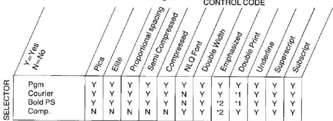
Table 4.10 Mixed Print Modes—Selector Switch/Control Codes
*1. Since near letter quality characters are printed with a double pass, the double print designation is ignored.
*2. If 15 or 17 pitch characters are selected through software, then ESC+E sets emphasis printing. If 15 or 17 pitch characters are selected by the selector switch, then ESC+E is ignored and 15 or 17 pitch characters will be printed.
IBM Proprinter Mode
| Y=Yes N=No | Pica | Elite | Compressed | NLQ Font | Double Width | Emphasized | Overline | Underline | Superscript | Subscript |
| Pica | - | *1 | *1 | Y | Y | Y | Y | Y | Y | Y |
| Elite | *1 | - | *1 | Y | Y | Y | Y | Y | Y | Y |
| Compressed | *1 | *1 | - | Y | Y | *2 | Y | Y | Y | Y |
| NLQ Font | Y | Y | Y | - | Y | Y | Y | Y | Y | Y |
| Double Width | Y | Y | Y | Y | - | Y | Y | Y | Y | Y |
| Emphasized | Y | Y | *2 | Y | Y | - | Y | Y | Y | Y |
| Overline | Y | Y | Y | Y | Y | Y | - | Y | Y | Y |
| Underline | Y | Y | Y | Y | Y | Y | Y | - | Y | Y |
| Superscript | Y | Y | Y | Y | Y | Y | Y | Y | - | N |
| Subscript | Y | Y | Y | Y | Y | Y | Y | Y | N | - |
Table 4.11 Mixed Print Modes—Control Codes Only
*1. Although different character pitches cannot be set simultaneously, they may be mixed on a single line.
*2. Only emphasized characters are printed.
Note: All character modes can be mixed on a single line.
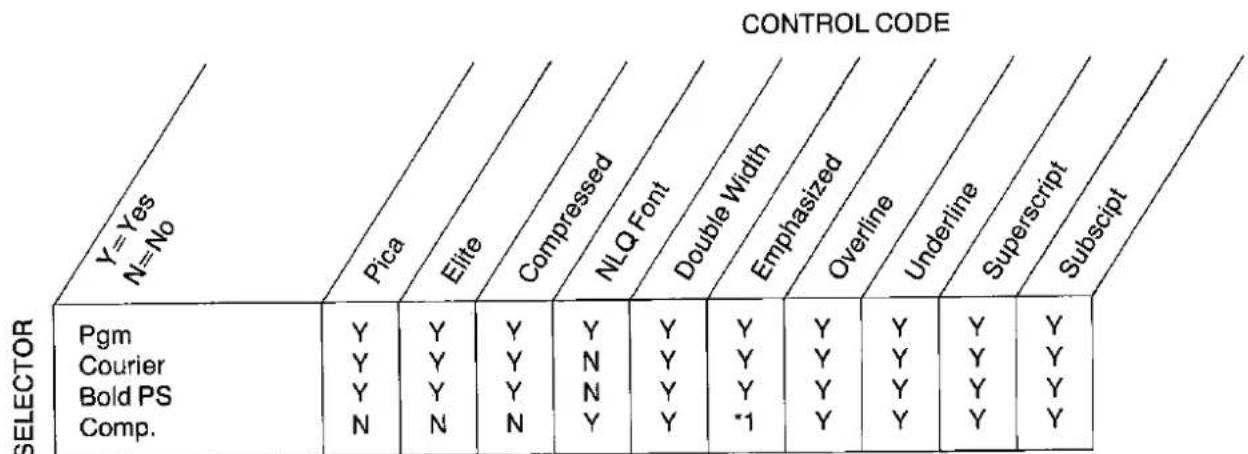
Table 4.12 Mixed Print Modes—Selector Switch/Control Codes
*1. If compressed pitch characters are selected through software, then ESC+E sets emphasis printing. If compressed pitch characters are selected by the selector switch, then ESC+E is ignored and compressed pitch characters will be printed.
4.9 DIP Switches and Control Codes
As explained in Section 3.3, DIP switch settings are read into printer memory when the printer is powered up. Certain printer functions set by these DIP switches can also be set by issuing the appropriate control commands. Table 4.13 illustrates those DIP switch functions which can also be set through software. THE CONTROL COMMAND WILL ALWAYS OVERRIDE THE CORRESPONDING DIP SWITCH SETTING(S).
| SWITCH NO. | FUNCTION | SETTING | ||||
| DIP SWITCH | SOFTWARE | |||||
| SW1SW5SW6SW7(Standard only) | Selection of International Char. Set•USA•France•England•Denmark I•Sweden•Italy•Spain | SW1ONONONONONONONONONONONONONONONONONONONONONONONONONONONONONONONONONONONONONONONONONONONONONONONONONONONONONONONONONONONONONONONONONONONONONONONONONONONONONONONONONONONONONONONONONONONONONONONONONONONONOFOFFOFFOFFOFFOFFOFFOFFOFFOFFOFFOFFOFFOFFOFFOFFOFFOFFOFFOFFOFFOFFOFFOFFOFFOFFOFFOFFOFFOFFOFFOFFOFFOFFOFFOFFOFFOFFOFFOFFOFFOFFOFFOFFOFFOFFOFFOFFOFFOFFOFFOFFOFFOFFOFFOFFOFFOFFOFFOFFOFFOFFOFFOFFOFFOFFOFFOFFOFFOFFOFFOFFOFFOFFOFFOFFOFFOFFOFFOFFOFFOFFOFFOFFOFFOFFOFFOFFOFFOFFOFFOFFOFFOFFOFFOFFOFFOFFOFFOFFOFFFFOFFOFFOFFOFFOFFOFFOFFOFFOFFOFFOFFOFFOFFOFFOFFOFFOFFOFFOFFOFFOFFOFFOFFOFFOFFOFFOFFOFFOFFOFFOFFOFFOFFOFFOFFOFFOFFOFFOFFOFFOFFOFFOFFOFFOFFOFFOFFOFFOFFOFFOFFOFFOFFOFFOFFOFFOFFOFFOFFOFFOFFOFFOFFOFFOFFOFFOFFOFFOFFOFFOFFOFFOFFOFFOFFOFFOFFOFFOFFOFFOFFOFFOFFOFFOFFOFFOFFOFFOFFOFFOFFOFFOFFOFFOFFOFFOFFOFFOFFFFFFFFFFFFFFFFFFFFFFFFFFFFFFFFFFFFFFFFFFFFFFFFFFFFFFFFFFFFFFFFFFFFFFFFFFFFFFFFFFFFFFFFFFFFFFFFFFFFFFFFFFFFFFFFFFFFFFFFFFFFFFFFFFFFFFFFFFFFFFFFFFFFFFFFFFFFFFFFFFFFFFFFFFFFFFFFFFFFFFFFFFFFFFFFFFFFFFFFFFFFFFFFFFFFFFFFFFFFFFFFFFFFFFFFFFFFFFFFFFFFFFFFFFFFFFFFFFFFFFFFFFFFFFFFFFFFFFFFFFFFFFFFFFFFFFFFFFFFFFFFFFFFFFFFFFFFFFFFFFFFFFFFFFFFFFFFFFFFFFFFFFFFFFFFFFFFFFFFFFFFFFFFFFFFFFFFFFFFFFFFFFFFFFFFFFFFFFFFFFFFFFFFFFFFFFFFFFFFFFFFFFFFFFFFFFFFFFFFFFFFFFFFFFFFFFFFFFFFFFFFFFFFFFFFFFFFFFFFFFFFFFFFFFFFFFFFFFFFFFFFFFFFFFFFFFFFFFFFFFFFFFFFFFFFFFFFFFFFFFFFFFFFFFFFFFFFFFFFFFFFFFFFFFFFFFFFFFFFFFFFFFFFFFFFFFFFFFFFFFFFFFFFFFFFFFFFFFFFFFFFFFFFFFFFFFFFFFFFFFFFFFFFFFFFFFFFFFFFFFFFFFFFFFFFFFFFFFFFFFFFFFFFFFFFFFFFFFFFFFFFFFFFFFFFFFFFFFFFFFFFFFFFFFFFFFFFFFFFFFFFFFFFFFFFFFFFFFFFFFFFFFFFFFFFFFFFFFFFFFFFFFFFFFFFFFFFFFFFFFFFFFFFFFFFFFFFFFFFFFFFFFFFFFFFFFFFFFFFFFFFFFFFFFFFFFFFFFFFFFFFFFFFFFFFFFFFFFFFFFFFFFFFFFFFFFFFFFFFFFFFFFFFFFFFFFFFFFFFFFFFFFFFFFFFFFFFFFFFFFFFFFFFFFFFFFFFFFFFFFFFFFFFFFFFFFFFFFFFFFFFFFFFFFFFFFFFFFFFFFFAFFFFFFFFFFFFFFFFFFFFFFFFFFFFFFFFFFFFFFFFFFFFFFFFFFFFFFFFFFFFFFFFFFFFFFFFFFFFFFFFFFFFFFFFFFFFFFFFFFFFFFFFFFFFFFFFFFFFFFFFFFFFFFFFFFFFFFFFFFFFFFFFFFFFFFFFFFFFFFFFFFFFFFFFFFFFFFFFFFFFFFFFFFFFFFFFFFFFFFFFFFFFFFFFFFFFFFFFFFFFFFFFFFFFFFFFFFFFFFFFFFFFFFFFFFFFFFFFFFFFFFFFFFFFFFFFFFFFFFFFFFFFFFFFFFFFFFFFFFFFFFFFFFFFFFFFFFFFFFFFFFFFFFFFFFFFFFFFFFFFFFFFFFFFFFFFFFFFFFFFFFFFFFFFFFFFFFFFFFFFFFFFFFFFFFFFFFFFFFFFFFFFFFFFFFFFFFFFFFFFFFFFFFFFFFFFFFFFFFFFFFFFFFFFFFFFFFFFFFFFFFFFFFFFFFFFFFFFFFFFFFFFFFFFFFFFFFFFFFFFFFFFFFFFFFFFFFFFFFFFFFFFFFFFFFFFFFFFFFFFFFFFFFFFFFFFFFFFFFFFFFFFFFFFFFFFFFFFFFFFFFFFFFFFFFFFFFFFFFFFFFFFFFFFFFFFFFFFFFFFFFFFFFFFFFFFFFFFFFFFFFFFFFFFFFFFFFFFFFFFFFFFFFFFFFFFFFFFFFFFFFFFFFFFFFFFFFFFFFFFFFFFFFFFFFFFFFFFFFFFFFFFFFFFFFFFFFFFFFFFFFFFFFFFFFFFFFFFFFFFFFFFFFFFFFFFFFFFFFFFFFFFFFFFFFFFFFFFFFFFFFFFFFFFFFFFFFFFFFFFFFFFFFFFFFFFFFFFFFFFFFFFFFFFFFFFFFFFFFFFFFFFFFFFFFFFFFFFFFFFFFFFFFFFFFFFFFFFFFFFFFFFFFFFFFFFFFFFFFFFFFFFFFFFFFFFFFFFFFFFFFFFFFFFFFFFFFFFFFFFFFFFFFFFFFFFFFFFFFFFFFFFFFFFFFFFFFFFFFFFFFFFFFFFFFFFFFFFFFFFFFFFFFFFFFFFFFFFFFFFFFFFFFFFFFFFFFFFFFFFFFFFFFFFFFFFFFFFFFFFFFFFFFFFFFFFFFFFFFFFFFFFFFFFFFFFFFFFFFFFFFFFFFFFFFFFFFFFFFFFFFFFFFFFFFFFFFFFFFFFFFFFFFFFFFFFFFFFFFFFFFFFFFFFFFFFFFFFFFFFFFFFFFFFFFFFFFFFFFFFFFFFFFFFFFFFFFFFFFFFFFFFFFFFFFFFFFFFFFFFFFFFFFFFFFFFFFFFFFFFFFFFFFFFFFFFFFFFFFFFFFFFFFFFFFFFFFFFFFFFFFFFFFFFFFFFFFFFFFFFFFFFFFFFFFFFFFFFFFFFFFFFFFFFFFFFFFFFFFFFFFFFFFFFFFFFFFFFFFFFFFFFFFFFFFFFFFFFFFFFFFFFFFFFFFFFFFFFFFFFFFFFFFFFFFFFFFFFFFFFFFFFFFFFFFFFFFFFFFFFFFFFFFFFFFFFFFFFFFFFFFFFFFFFFFFFFFFFFFFFFFFFFFFFFFFFFFFFFFFFFFFFFFFFFFFFFFFFFFFFFFFFFFFFFFFFFFFFFFFFFFFFFFFFFFFFFFFFFFFFFFFFFFFFFFFFFFFFFFFFFFFFFFFFFFFFFFFFFFFFFFFFFFFFFFFFFFFFFFFFFFFFFFFFFFFFFFFFFFFFFFFFFFFFFFFFFFFFFFFFFFFFFFFFFFFFFFFFFFFFFFFFFFFFFFFFFFFFFFFFFFFFFFFFFFFFFFFFFFFFFFFFFFFFFFFFFFFFFFFFFFFFFFFFFFFFFFFFFFFFFFFFFFFFFFFFFFFFFFFFFFFFFFFFFFFFFFFFFFFFFFFFFFFFFFFFFFFFFFFFFFFFFFFFFFFFFFFFFFFFFFFFFFFFFFFFFFFFFFFFFFFFFFFFFFFFFFFFFFFFFFFFFFFFFFFFFFFFFFFFFFFFFFFFFFFFFFFFFFFFFFFFFFFFFFFFFFFFFFFFFFFFFFFFFFFEFFFFFFFFFFFFFFFFFFFFFFFFFFFFFFFFFFFFFFFFFFFFFFFFFFFFFFFFFFFFFFFFFFFFFFFFFFFFFFFFFFFFFFFFFFFFFFFFFFFFFFFFFFFFFFFFFFFFFFFFFFFFFFFFFFFFFFFFFFFFFFFFFFFFFFFFFFFFFFFFFFFFFFFFFFFFFFFFFFFFFFFFFFFFFFFFFFFFFFFFFFFFFFFFFFFFFFFFFFFFFFFFFFFFFFFFFFFFFFFFFFFFFFFFFFFFFFFFFFFFFFFFFFFFFFFFFFFFFFFFFFFFFFFFFFFFFFFFFFFFFFFFFFFFFFFFFFFFFFFFFFFFFFFFFFFFFFFFFFFFFFFFFFFFFFFFFFFFFFFFFFFFFFFFFFFFFFFFFFFFFFFFFFFFFFFFFFFFFFFFFFFFFFFFFFFFFFFFFFFFFFFFFFFFFFFFFFFFFFFFFFFFFFFFFFFFFFFFFFFFFFFFFFFFFFFFFFFFFFFFFFFFFFFFFFFFFFFFFFFFFFFFFFFFFFFFFFFFFFFFFFFFFFFFFFFFFFFFFFFFFFFFFFFFFFFFFFFFFFFFFFFFFFFFFFFFFFFFFFFFFFFFFFFFFFFFFFFFFFFFFFFFFFFFFFFFFFFFFFFFFFFFFFFFFFFFFFFFFFFFFFFFFFFFFFFFFFFFFFFFFFFFFFFFFFFFFFFFFFFFFFFFFFFFFFFFFFFFFFFFFFFFFFFFFFFFFFFFFFFFFFFFFFFFFFFFFFFFFFFFFFFFFFFFFFFFFFFFFFFFFFFFFFFFFFFFFFFFFFFFFFFFFFFFFFFFFFFFFFFFFFFFFFFFFFFFFFFFFFFFFFFFFFFFFFFFFFFFFFFFFFFFFFFFFFFFFFFFFFFFFFFFFFFFFFFFFFFFFFFFFFFFFFFFFFFFFFFFFFFFFFFFFFFFFFFFFFFFFFFFFFFFFFFFFFFFFFFFFFFFFFFFFFFFFFFFFFFFFFFFFFFFFFFFFFFFFFFFFFFFFFFFFFFFFFFFFFFFFFFFFFFFFFFFFFFFFFFFFFFFFFFFFFFFFFFFFFFFFFFFFFFFFFFFFFFFFFFFFFFFFFFFFFFFFFFFFFFFFFFFFFFFFFFFFFFFFFFFFFFFFFFFFFFFFFFFFFFFFFFFFFFFFFFFFFFFFFFFFFFFFFFFFFFFFFFFFFFFFFFFFFFFFFFFFFFFFFFFFFFFFFFFFFFFFFFFFF(F) | SW1SW5SW6SW7ESC+R+0ESC+R+1ESC+R+3ESC+R+4ESC+R+5ESC+R+6ESC+R+7 | SW1SW5SW6SW7ESC+R+0ESC+R+1ESC+R+3ESC+R+4ESC+R+5ESC+R+6ESC+R+7 | SW1SW5SW6SW7ESC+R+0ESC+R+1ESC+R+3ESC+R+4ESC+R+5ESC+R+6ESC+R+7 | SW1SW5SW6SW7ESC+8ESC+9ESC+9ESC+5+1ESC+5+0ESC+N+6ESC+OESC+OESC+6ESC+7ESC+7ESC+=ESC+#ESC+#ESC+#ESC+#ESC+#ESC+#ESC+#ESC+#ESC+#ESC+#ESC+#ESC+#ESC+#ESC+#ESC+#ESC+#ESC+#ESC+#ESC+#ESC+#ESC+#ESC+#ESC+#ESC+#ESC+#ESC+#ESC+#ESC+#ESC+#ESC+#ESC+#ESC+#ESC+#ESC+#ESC+#ESC+#ESC+#ESC+#ESC+#ESC+#ESC+#ESC+#ESC+#ESC+#ESC+#ESC+#ESC+#ESC+#ESC+#ESC+#ESC##ESC+#ESC##ESC##ESC##ESC##ESC##ESC##ESC##ESC##ESC##ESC##ESC##ESC##ESC##ESC##ESC##ESC##ESC##ESC##ESC##ESC##ESC##ESC##ESC##ESC##ESC##ESC##ESC##ESC##ESC##ESC##ESC##ESC##ESC##ESC##ESC##ESC##ESC##ESC##ESC##ESC##ESC##ESC##ESC##ESC##ESC##ESC##ESC##ESC##ESC##ESC##ESC###ESC##ESC##ESC##ESC##ESC##ESC##ESC##ESC##ESC##ESC##ESC##ESC##ESC##ESC##ESC##ESC##ESC##ESC##ESC##ESC##ESC##ESC##ESC##ESC##ESC##ESC##ESC##ESC##ESC##ESC##ESC##ESC##ESC##ESC##ESC##ESC##ESC##ESC##ESC##ESC##ESC##ESC##ESC##ESC##ESC##ESC##ESC##ESC##ESC##ESC###### |
Table 4.13 Software Control of DIP Switch Functions
Note:
- Japan (ESC+R+8), Norway (ESC+R+9), and Denmark II (ESC+R+10) international character sets are software-selectable only.
- The AUTO FEED XT (SW3) setting enables the printer to issue a line feed after a carriage return. By inserting LPRINT CHR\$(10) in the appropriate portions of a program, you can also issue a line feed after a carriage return. Refer to the LF designation, Section 4.7.
5.1 Parallel Interfacing
Communication with a computer is accomplished through a parallel interface based on the Centronics standard.
Specifications:
●data transfer speed: 1000 cps minimum
•synchronization: external STROBE pulse
- logic levels: TTL
●handshaking: BUSY and ACK signals
- connector type: 57-30360 (AMPHENOL) or equivalent
- cable: use a shielded cable 3 meters or less in length.
When the printer is processing data, the BUSY signal is high. The printer will not accept new data from the computer. After the processing is completed, the BUSY signal goes low. (The BUSY signal is also high when the printer is OFF LINE). When this occurs, the ACK signal goes low indicating to the computer that the data has been processed and the printer is ready to accept more data. This handshaking routine occurs each time a character is sent to the printer.
| BUSY | SLCT | PO | ERROR | |
| ON LINE | LOW | HIGH | LOW | HIGH |
| OFF LINE | HIGH | LOW | LOW | LOW |
| PAPER OUT | HIGH | LOW | HIGH | LOW |
Table 5.1 Printer Status Signals
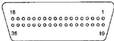
Note: This is not a 57-30360 connector.
Figure 5.1 Parallel Interface Connector (Printer side)
| Signal pin | Return side pin | Signal | Direction |
| 1 | 19 | STB | Input |
| 2 | 20 | DATA 1 | Input |
| 3 | 21 | DATA 2 | |
| 4 | 22 | DATA 3 | |
| 5 | 23 | DATA 4 | |
| 6 | 24 | DATA 5 | |
| 7 | 25 | DATA 6 | |
| 8 | 26 | DATA 7 | |
| 9 | 27 | DATA 8 | |
| 10 | 28 | ACK | Output |
| 11 | 29 | BUSY | Output |
| 12 | PO | Output | |
| 13 | SLCT | Output | |
| 14 | AUTO FEED XT | Input | |
| 15 | |||
| 16 | SG | ||
| 17 | FG | ||
| 18 | +5 V | Output | |
| 31 | 30 | PRIME | Input |
| 32 | ERROR | Output | |
| 33 | SG | ||
| 34 | |||
| 35 | |||
| 36 |
Table 5.2 Connector Pin Configuration
5.2 | Connector pin signals
Notes:
- "INPUT" refers to a signal coming into the printer. "OUTPUT" denotes a signal exiting the printer.
- "RETURN" denotes the return side wire of a twisted pair cable and is connected to signal ground.
- All interface signals are at TTL levels.
STB... STROBE
- This is a synchronizing input signal to read data into the printer.
- This signal is normally high. Data is read in when it goes low.
- The pulse must be low for at least 1 microsecond.
DATA 1-DATA 8
- These are the input signals which carry the 8 data bits of information.
- The signal is read in synchronization with the STROBE pulse. A high level indicates a logical "1".
- The signal must be present 0.5 microsecond before and after the STROBE pulse.
ACK... ACKNOWLEDGE
- This is an output signal to the computer indicating that the printer is ready to receive the next block of data. It is sent out when the BUSY signal drops from high to low. Therefore, it can be thought of as a data request pulse.
●The signal is normally high. When the condition becomes true, the signal goes low. - The ACK signal is automatically sent whenever the printer is switched ON LINE.
BUSY
- This output signal indicates the status of the printer. The signal is high when the printer is busy and cannot receive data.
●The signal is high under the following conditions: - receive buffer full
- printer is processing data
- printer is OFF LINE
- printer is in an error condition
PO... PAPER OUT
●This output signal indicates that there are only 13 lines of paper remaining.
- The signal is normally low and goes high during a "Paper Out" condition.
SLCT... SELECT
-
SELECT is an output signal which indicates the ON LINE or OFF LINE state of the printer. The signal is high in the ON LINE state and low when OFF LINE.
●The printer enters the ON LINE state: -
when the printer is turned on
- when PRIME is received
- when the RESET command is received
- when the ON LINE switch is pressed
●The printer enters the OFF LINE state:
- when the printer is out of paper
- when the printer is switched OFF LINE
AUTO FEED XT (AFXT)
- This input signal determines if a line feed (LF) command will be added to each carriage return (CR).
- When is low, CR+LF action occurs. When is high, only a carriage return is performed.
- DIP SW3 can alter the response by the printer to an AFXT signal. If SW3 is ON, the printer will perform a CR+LF regardless of the level of the incoming signal. When SW3 is OFF, this automatic action is disabled.
SG... SIGNAL GROUND
- The twisted pair return wires (pins 19–30) are connected to signal ground.
FG... FRAME GROUND
●Frame ground is the same as chassis ground.
+5 V
This is for evaluation only. It should not be used to supply power for external equipment.
PRIME
This input signal is used to initialize the printer. The signal is normally high and goes low to reset the printer. It can be received anytime during printer operation.
ERROR
This output signal is an "error" or "fault" condition. Normally high, this signal goes low when an error occurs. An error condition can be caused by:
- a "Paper Out" condition.
- the printer is OFF LINE
- an overload condition exists
Timing Chart
(When normal printing code is received)
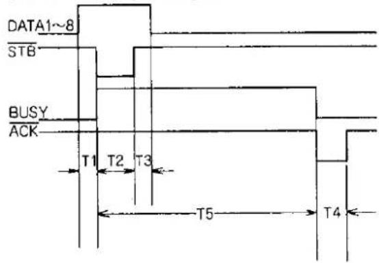
T1... 0.5μs (Min)
T2... 1μs (Min)
T3... 0.5μs (Min)
T4... 5μs (Max)
T5... 1ms or less when not buffer full
1s or less when buffer full
Figure 5.2 Timing Diagram
The printer does not require any routine maintenance. However, reasonable care of the printer will extend its life. The following preventive and periodic measures are recommended:
6.1 Preventive Maintenance
- Keep all liquids away from the printer. Accidental spillage of a liquid into the printer can cause severe damage.
- Do not block the air flow around the printer. Do not place books, paper, or other items on top of the printer.
- Special care should be taken to protect the printer if it is used in an unfriendly environment such as a machine shop, a dusty or sandy area, etc.
- When transporting the printer, be sure the carriage stoppers are in place. This will help prevent damage to the print head.
- The life of the print head can be extended by observing a few simple precautions.
- Do not operate the printer without paper and a ribbon cassette installed.
- Avoid continuous use of the same pins (underline, semi-graphics, etc.) without allowing the print head time to cool.
- Do not obstruct the movement of the print head while in operation.
- If the printer is not going to be used for an extended period, unplug the power cord.
6.2 | Periodic Maintenance
Cleaning the unit is the most important action the user can perform. The frequency of cleaning is dependent upon the environment.
- Turn the power OFF.
- Clean the case and covers with a soft cloth. Use any mild commercial cleaner.
- Remove the top and the smoked plastic covers. Vacuum or dust the inside area of the unit. Be very careful not to damage the flex ribbon cable and the carriage drive belt.
- The platen should be cleaned with denature alcohol only.
- The carriage guide bar can be lubricated with a very light oil.
Ribbon Cassette (KX-P110)
A single ribbon permits the printing of about 3 million characters. When the printing starts to fade, gently push the counter spring in the ribbon cassette hole with the tip of a ballpoint pen or other object. Once the ribbon cassette is mounted onto the carriage and printing is performed for a short time, the characters become thicker.
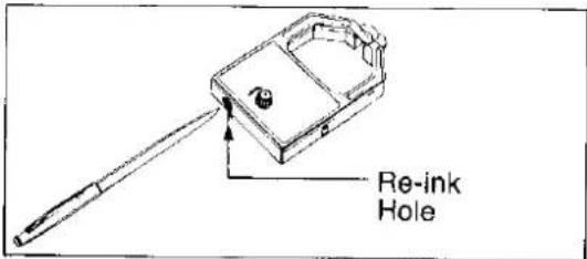
Note:
Do not re-ink the ribbon before printing starts to fade. If the ribbon has too much ink the characters may smear when printed.
- Wear and tear of the print head pins may cause serious damage of the ribbon and printing to fade. In such case the printer needs servicing.
- Dust and paper trash on the carriage shaft and the carriage guide shaft may obstruct the movement of the carriage. Clean them with a soft cloth. Periodical cleaning is necessary for proper operation and extended product life.
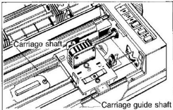
6.3 Troubleshooting
Most problems associated with the printer can be traced to improper setup, installation, or cabling. Table 6.1 will assist the user in identifying and
correcting some of the more common problems. If you need additional help, contact the store from which the unit was purchased.
| SYMPTOM | POSSIBLE CAUSE | PROBABLE SOLUTION |
| Printer Dead | No AC PowerFuse blown | Check Power CordReplace fuse |
| Power on but printer not printing | Printer not ON LINE; out of paper | Press ON LINE switch; replace paper |
| Printer won't go ON LINE | Out of paper | Replace paper |
| Paper slips around platen | Paper feed selector in TRACTOR position. | Set selector to FRICTION |
| Head moves but does not print | Ribbon not installed correctly | Re-inset ribbon |
| Paper bunches up around platen | No reverse tension on paper | Set paper supply lower than printer |
| Continuous Paper/Error indicator flashing | OVERLOAD condition | Carriage travel path blocked; carriage stoppers not removed |
| Printout double-spaced or no spacing | AFXT switch improperly set | Set DIP switchSW3—as required |
| Cannot print ASCII characters with code above 127, italic characters printing | 7 bit/8 bit switch set incorrectly on printer or interface | Set DIP switchSW8—as required |
| Cannot change print mode from computer | Print mode switch set incorrectly | Normal condition.Refer to Section 3.1 |
Table 6.1 Troubleshooting
Standard Mode Character Set
| 0 | 1 | 2 | 3 | 4 | 5 | 6 | 7 | 8 | 9 | A | B | C | D | E | F | |
| 0 | NUL | SP | 0 | @ | P | ' | p | SP | 0 | @ | P | ' | p | |||
| 1 | DC1 | ! | 1 | A | Q | a | q | DC1 | ! | 1 | A | Q | a | q | ||
| 2 | DC2 | " | 2 | B | R | b | r | DC2 | " | 2 | B | R | b | r | ||
| 3 | DC3 | # | 3 | C | S | c | s | DC3 | # | 3 | C | S | c | s | ||
| 4 | DC4 | 4 | D | T | d | t | DC4 | 4 | D | T | d | t | ||||
| 5 | % | 5 | E | U | e | u | % | 5 | E | U | e | u | ||||
| 6 | & | 6 | F | V | f | v | & | 6 | F | V | f | v | ||||
| 7 | BEL | ' | 7 | G | W | g | w | BEL | ' | 7 | G | W | g | w | ||
| 8 | BS | CAN | ( | 8 | H | X | h | x | BS | CAN | ( | 8 | H | X | h | x |
| 9 | HT | ) | 9 | I | Y | i | y | HT | ) | 9 | I | Y | i | y | ||
| A | LF | * | : | J | Z | j | z | LF | * | : | J | Z | j | z | ||
| B | VT | ESC | + | ; | K | [ | k | { | VT | ESC | + | ; | K | [ | k | { |
| C | FF | , | < | L | \ | I | | | FF | , | < | L | \ | I | / | ||
| D | CR | - | = | M | ] | m | } | CR | - | = | M | ] | m | } | ||
| E | SO | . | > | N | ^ | n | ~ | SO | . | > | N | ^ | n | ~ | ||
| F | SI | / | ? | O | _ | o | DEL | SI | / | ? | O | _ | o | DEL |
IBM Character Set 1
| 0 | 1 | 2 | 3 | 4 | 5 | 6 | 7 | 8 | 9 | A | B | C | D | E | F | |
| 0 | NUL | SP | 0 | @ | P | ' | p | á | ≡ | |||||||
| 1 | DC1 | ! | 1 | A | Q | a | q | DC1 | í | ± | ||||||
| 2 | DC2 | " | 2 | B | R | b | r | DC2 | ó | ≥ | ||||||
| 3 | DC3 | # | 3 | C | S | c | s | DC3 | ú | ≤ | ||||||
| 4 | DC4 | 4 | D | T | d | t | DC4 | ñ | \Sigma | |||||||
| 5 | % | 5 | E | U | e | u | Ñ | \sigma | ||||||||
| 6 | & | 6 | F | V | f | v | a | \mu | ÷ | |||||||
| 7 | BEL | , | 7 | G | W | g | w | BEL | o | \gamma | ≈ | |||||
| 8 | BS | CAN | ( | 8 | H | X | h | x | BS | CAN | ¿ | \Phi | ° | |||
| 9 | HT | ) | 9 | I | Y | i | y | HT | \theta | ■ | ||||||
| A | LF | * | : | J | Z | j | z | LF | \Omega | ● | ||||||
| B | VT | ESC | + | ; | K | [ | k | VT | ESC | 1⁄2 | δ | √ | ||||
| C | FF | , | < | L | \ | l | FF | 1⁄4 | \infty | " | ||||||
| D | CR | - | = | M | ] | m | CR | i | \phi | ^2 | ||||||
| E | SO | . | > | N | ^ | n | ~ | SO | << | \epsilon$ | ■ | |||||
| F | SI | / | ? | O | _ | o | SI | >> | ∩ | SP |
IBM Character Set 2
| 0 | 1 | 2 | 3 | 4 | 5 | 6 | 7 | 8 | 9 | A | B | C | D | E | F | ||
| 0 | NUL | SP | 0 | @ | P | ' | p | Ç | É | á | ≡ | ||||||
| 1 | DC1 | ! | 1 | A | Q | a | q | ü | æ | í | ± | ||||||
| 2 | DC2 | " | 2 | B | R | b | r | é | Æ | ó | ≥ | ||||||
| 3 | ♥ | DC3 | # | 3 | C | S | c | s | â | ô | ú | ≤ | |||||
| 4 | ♦ | DC4 | 4 | D | T | d | t | ä | ö | ñ | \Sigma | ||||||
| 5 | ♣ | § | % | 5 | E | U | e | u | à | ò | Ñ | \sigma | J | ||||
| 6 | ♠ | & | 6 | F | V | f | v | å | û | a | \mu | ÷ | |||||
| 7 | BEL | ' | 7 | G | W | g | w | ç | ù | o | \gamma | ≈ | |||||
| 8 | BS | CAN | ( | 8 | H | X | h | x | ê | ÿ | ¿ | \Phi | ° | ||||
| 9 | HT | ) | 9 | I | Y | i | y | ë | Ö | — | \theta | ■ | |||||
| A | LF | * | : | J | Z | j | z | è | Ü | ¬ | \Omega | • | |||||
| B | VT | ESC | + | ; | K | I | k | i | φ | 1⁄2 | δ | √ | |||||
| C | FF | , | < | L | \ | l | | | î | £ | 1⁄4 | \infty | ° | |||||
| D | CR | - | = | M | ] | m | i | ¥ | i | \phi$ | 2 | ||||||
| E | SO | , | > | N | ^ | n | ~ | Ä | Pt | << | ε | ■ | |||||
| F | SI | / | ? | O | _ | o | Å | f | >> | ∩ | SP | ||||||
IBM All Character Chart
| 0 | 1 | 2 | 3 | 4 | 5 | 6 | 7 | 8 | 9 | A | B | C | D | E | F | ||
| 0 | SP | SP | SP | 0 | @ | P | ' | p | Ç | É | á | ≡ | |||||
| 1 | SP | SP | ! | 1 | A | Q | a | q | ü | æ | í | ± | |||||
| 2 | SP | SP | " | 2 | B | R | b | r | é | Æ | ó | ≥ | |||||
| 3 | ♥ | SP | # | 3 | C | S | c | s | å | ð | ú | ≤ | |||||
| 4 | ♦ | ¶ | § | 4 | D | T | d | t | ä | ö | ñ | ||||||
| 5 | ♣ | § | % | 5 | E | U | e | u | à | ò | Ñ | J | |||||
| 6 | ♠ | SP | & | 6 | F | V | f | v | å | û | ÷ | ||||||
| 7 | SP | SP | ' | 7 | G | W | g | w | ç | ù | ≈ | ||||||
| 8 | SP | SP | ( | 8 | H | X | h | x | ē | ÿ | ¿ | ° | |||||
| 9 | SP | SP | ) | 9 | I | Y | i | y | è | Ö | — | ■ | |||||
| A | SP | → | * | : | J | Z | j | z | è | Ü | ¬ | • | |||||
| B | SP | ← | + | ; | K | [ | k | { | ï | ¢ | 1⁄2 | √ | |||||
| C | SP | SP | . | < | L | \ | i | | | î | £ | 1⁄4 | ° | |||||
| D | SP | SP | - | = | M | ] | m | } | i | ¥ | i | ^2 | |||||
| E | SP | SP | . | > | N | ^ | n | ~ | Ä | Pt | << | ■ | |||||
| F | SP | ∅ | / | ? | O | _ | o | SP | Å | ƒ | >> | SP |
International Character Set
| n | 35_0 23_H | 36_0 24_H | 64_0 40_H | 91_0 5B_H | 92_0 5C_H | 93_0 5D_H | 94_0 5E_H | 96_0 60_H | 123_0 7B_H | 124_0 7C_H | 125_0 7D_H | 126_0 7E_H | |
| USA | 0 | # | @ | [ | \ | ] | ^ | ' | | | ~ | |||
| FRANCE | 1 | # | à | ° | ç | § | ^ | ' | é | ù | è | .. | |
| 2 | Ineffective | ||||||||||||
| ENGLAND | 3 | £ | @ | [ | \ | ] | ^ | ' | | | ~ | |||
| DENMARK I | 4 | # | @ | Æ | ∅ | Å | ^ | ' | æ | ø | å | ~ | |
| SWEDEN | 5 | # | ø | É | Å | Ö | Å | Ü | é | ä | ö | å | ü |
| ITALY | 6 | # | @ | ° | \ | é | ^ | ù | à | ò | è | i | |
| SPAIN | 7 | Pt | @ | i | Ñ | ¿ | ^ | ' | .. | ñ | } | ~ | |
| *JAPAN | 8 | # | @ | [ | ¥ | ] | ^ | ' | | | ~ | |||
| *NORWAY | 9 | # | ø | É | Æ | ∅ | Å | Ü | é | æ | ø | å | ü |
| *DENMARK II | 10 | # | É | Æ | ∅ | Å | Ü | é | æ | ø | å | ü | |
*Accessible only through software
\*Italic International Character Set
| LOCATION | CHAR. | LOCATION | CHAR. | LOCATION | CHAR. | LOCATION | CHAR. | ||||
| DEC | HEX | DEC | HEX | DEC | HEX | DEC | HEX | ||||
| 128 | 80 | à | 137 | 89 | 146 | 92 | AE | 155 | 9B | ö | |
| 129 | 81 | è | 138 | 8A | ñ | 147 | 93 | æ | 156 | 9C | ü |
| 130 | 82 | ù | 139 | 8B | α | 148 | 94 | ∅ | 157 | 9D | É |
| 131 | 83 | ò | 140 | 8C | Pt | 149 | 95 | ø | 158 | 9E | é |
| 132 | 84 | i | 141 | 8D | Å | 150 | 96 | 159 | 9F | ¥ | |
| 133 | 85 | ° | 142 | 8E | à | 151 | 97 | Å | 255 | FF | ∅ |
| 134 | 86 | £ | 143 | 8F | ç | 152 | 98 | Ö | |||
| 135 | 87 | j | 144 | 90 | § | 153 | 99 | Ü | |||
| 136 | 88 | ¿ | 145 | 91 | ß | 154 | 9A | ä | |||
*Accessible only in Standard Mode
Proportional Spacing Tables
Standard Mode Characters
| ASCII code | Char. | Width |
| 0 | A | 12 |
| 1 | B | 12 |
| 2 | C | 11 |
| 3 | D | 10 |
| 4 | E | 8 |
| 5 | F | 12 |
| 6 | G | 12 |
| 7 | H | 5 |
| 8 | I | 12 |
| 9 | J | 12 |
| 10 | K | 11 |
| 11 | L | 12 |
| 12 | M | 12 |
| 13 | N | 12 |
| 14 | O | 12 |
| 15 | P | 11 |
| 16 | Q | 10 |
| 17 | R | 11 |
| 18 | S | 12 |
| 19 | T | 12 |
| 20 | U | 12 |
| 21 | V | 12 |
| 22 | W | 8 |
| 23 | X | 12 |
| 24 | Y | 12 |
| 25 | Z | 12 |
| 26 | A | 12 |
| 27 | B | 10 |
| 28 | C | 11 |
| 29 | D | 12 |
| 30 | E | 12 |
| 31 | F | 12 |
| 32 | G | 12 |
| 33 | H | 5 |
| 34 | I | 8 |
| 35 | J | 12 |
| 36 | K | 12 |
| 37 | L | 12 |
| 38 | M | 12 |
| 39 | N | 5 |
| 40 | O | 7 |
| 41 | O | 7 |
| 42 | P | 12 |
| 43 | Q | 12 |
| 44 | R | 12 |
| 45 | S | 12 |
| 46 | T | 6 |
| 47 | U | 10 |
| 48 | V | 12 |
| 49 | W | 12 |
| 50 | X | 12 |
| 51 | Y | 12 |
| 52 | Z | 12 |
| 53 | A | 12 |
| 54 | B | 12 |
| 55 | C | 12 |
| 56 | D | 12 |
| 57 | E | 12 |
| 58 | F | 12 |
| 59 | G | 12 |
| 60 | H | 12 |
| 61 | I | 12 |
| 62 | J | 10 |
| 63 | 12 |
| ASCII code | Char. | Width |
| 64 | @ | 12 |
| 65 | A | 12 |
| 66 | B | 12 |
| 67 | C | 12 |
| 68 | D | 12 |
| 69 | E | 12 |
| 70 | F | 12 |
| 71 | G | 12 |
| 72 | H | 12 |
| 73 | I | 8 |
| 74 | J | 11 |
| 75 | K | 12 |
| 76 | L | 12 |
| 77 | M | 12 |
| 78 | N | 12 |
| 79 | O | 12 |
| 80 | P | 12 |
| 81 | Q | 12 |
| 82 | R | 12 |
| 83 | S | 12 |
| 84 | T | 12 |
| 85 | U | 12 |
| 86 | V | 12 |
| 87 | W | 12 |
| 88 | X | 10 |
| 89 | Y | 12 |
| 90 | Z | 10 |
| 91 | I | 8 |
| 92 | J | 10 |
| 93 | K | 8 |
| 94 | L | 12 |
| 95 | M | 12 |
| 96 | n | 11 |
| 97 | o | 12 |
| 98 | p | 11 |
| 99 | q | 11 |
| 100 | r | 11 |
| 101 | s | 12 |
| 102 | t | 11 |
| 103 | u | 12 |
| 104 | v | 12 |
| 105 | w | 13 |
| 106 | x | 10 |
| 107 | y | 12 |
| 108 | z | 10 |
| 109 | w | 13 |
| 110 | u | 12 |
| 111 | y | 12 |
| 112 | z | 10 |
| 113 | u | 9 |
| 114 | y | 12 |
| 115 | s | 12 |
| 116 | t | 11 |
| 117 | u | 12 |
| 118 | y | 12 |
| 119 | w | 13 |
| 120 | x | 10 |
| 121 | y | 12 |
| 122 | z | 10 |
| 123 | t | 12 |
| 124 | u | 12 |
| 125 | y | 12 |
| 126 | z | 12 |
| 127 | e | 12 |
| ASCII code | Char. | Width |
| 128 | 11 | |
| 129 | 11 | |
| 130 | 11 | |
| 131 | 11 | |
| 132 | 8 | |
| 133 | ^ | 8 |
| 134 | 12 | |
| 135 | 10 | |
| 136 | 11 | |
| 137 | N | 12 |
| 138 | 12 | |
| 139 | 12 | |
| 140 | 12 | |
| 141 | A | 12 |
| 142 | 11 | |
| 143 | 11 | |
| 144 | S | 12 |
| 145 | 11 | |
| 146 | AE | 12 |
| 147 | 12 | |
| 148 | 12 | |
| 149 | 11 | |
| 150 | 9 | |
| 151 | A | 12 |
| 152 | O | 12 |
| 153 | U | 12 |
| 154 | 11 | |
| 155 | 11 | |
| 156 | 12 | |
| 157 | E | 12 |
| 158 | 11 | |
| 159 | 12 | |
| 160 | 12 | |
| 161 | 10 | |
| 162 | 10 | |
| 163 | 12 | |
| 164 | 11 | |
| 165 | % | 12 |
| 166 | \& | 12 |
| 167 | · | 6 |
| 168 | ( | 8 |
| 169 | ) | 8 |
| 170 | 12 | |
| 171 | + | 12 |
| 172 | · | 7 |
| 173 | - | 12 |
| 174 | · | 7 |
| 175 | 10 | |
| 176 | O | 12 |
| 177 | 12 | |
| 178 | 12 | |
| 179 | 2 | 12 |
| 180 | 3 | 12 |
| 181 | 4 | 12 |
| 182 | 5 | 12 |
| 183 | 6 | 12 |
| 184 | 8 | 12 |
| 185 | 9 | 12 |
| 186 | 7 | 7 |
| 187 | 7 | |
| 188 | 10 | |
| 189 | = | 11 |
| 190 | 9 | |
| 191 | 11 |
| ASCII code | Char. | Width |
| 192 | @ | 12 |
| 193 | A | 12 |
| 194 | B | 12 |
| 195 | C | 12 |
| 196 | D | 12 |
| 197 | E | 12 |
| 198 | F | 12 |
| 199 | G | 12 |
| 200 | H | 12 |
| 201 | I | 10 |
| 202 | J | 12 |
| 203 | K | 12 |
| 204 | L | 10 |
| 205 | M | 12 |
| 206 | N | 12 |
| 207 | O | 12 |
| 208 | P | 12 |
| 209 | Q | 12 |
| 210 | R | 12 |
| 211 | S | 12 |
| 212 | T | 12 |
| 213 | U | 12 |
| 214 | V | 12 |
| 215 | W | 12 |
| 216 | X | 12 |
| 217 | Y | 12 |
| 218 | Z | 12 |
| 219 | ( 7 \ 1 \ 1 \ 1 \ 1 \ 1 \ 1 \ 1 \ 1 \ 1 \ 1 \ 1 \ 1 \ 1 \ 1 \ 1 \ 1 \ 1 \ 1 \ 1 \ 1 \ 1 \ 1 \ 1 \ 1 \ 1 \ 1 \ 1 \ 1 \ 1 \ 1 \ 1 \ 1 \ 1 \ 1 ) | |
| 220 | ||
| 221 | ||
| 222 | ||
| 223 | ||
| 224 | ||
| 225 | ||
| 226 | ||
| 227 | ||
| 228 | ||
| 229 | ||
| 230 | ||
| 231 | ||
| 232 | ||
| 233 | ||
| 234 | ||
| 235 | ||
| 236 | ||
| 237 | ||
| 238 | ||
| 239 | ||
| 240 | ||
| 241 | ||
| 242 | ||
| 243 | ||
| 244 | ||
| 245 | ||
| 246 | ||
| 247 | ||
| 248 | ||
| 249 | ||
| 250 | ||
| 251 | ||
| 252 | ||
| 253 | ||
| 254 | ||
| 255 |
Unit: 1120 inch (0.21 mm)
IBM Graphics Characters
Effective only when the print mode selector is set to "Bold PS".
| ASCII code | Char. | Width |
| 3 | ♥ | 12 |
| 4 | ♦ | 12 |
| 5 | ♣ | 12 |
| 6 | ♠ | 12 |
| 20 | ¶ | 12 |
| 21 | § | 10 |
| 26 | → | 12 |
| 27 | ← | 12 |
| 31 | ∅ | 12 |
| 128 | Ç | 12 |
| 129 | ü | 11 |
| 130 | é | 12 |
| 131 | ä | 12 |
| 132 | ä | 12 |
| 133 | ä | 12 |
| 134 | ä | 12 |
| 135 | ç | 11 |
| 136 | ö | 12 |
| 137 | õ | 12 |
| 138 | è | 12 |
| 139 | i | 8 |
| 140 | i | 8 |
| 141 | i | 8 |
| 142 | Ä | 12 |
| 143 | Ä | 12 |
| 144 | É | 12 |
| 145 | æ | 12 |
| 146 | Æ | 12 |
| 147 | ö | 10 |
| 148 | ö | 10 |
| 149 | ö | 10 |
| 150 | ü | 11 |
| 151 | ü | 11 |
| 152 | y | 11 |
| 153 | Ö | 12 |
| 154 | Ü | 12 |
| 155 | ¢ | 11 |
| 156 | £ | 12 |
| 157 | ¥ | 12 |
| 158 | Pt | 12 |
| 159 | f | 12 |
| 160 | á | 12 |
| 161 | i | 8 |
| 162 | ö | 10 |
| 163 | ü | 11 |
| 164 | ñ | 11 |
| 165 | Ñ | 12 |
| 166 | a | 12 |
| 167 | ø | 12 |
| 168 | ¿ | 12 |
| 169 | ¬ | 12 |
| 170 | 1⁄2 | 12 |
| 171 | 1⁄4 | 12 |
| 172 | i | 5 |
| 173 | << | 12 |
| 174 | >> | 12 |
| 175 | ||
| 224 | α | 12 |
| 225 | β | 12 |
| 226 | Γ | 12 |
| 227 | π | 12 |
| 228 | Σ | 12 |
| ASCII code | Char. | Width |
| 229 | 12 | |
| 230 | 12 | |
| 231 | 12 | |
| 232 | 12 | |
| 233 | 12 | |
| 234 | 12 | |
| 235 | 12 | |
| 236 | 12 | |
| 237 | 12 | |
| 238 | 12 | |
| 239 | 12 | |
| 240 | 12 | |
| 241 | ± | 12 |
| 242 | ≥ | 12 |
| 243 | ≤ | 12 |
| 246 | ÷ | 12 |
| 247 | ≈ | 12 |
| 248 | ^o | 8 |
| 249 | ■ | 12 |
| 250 | ● | 12 |
| 251 | v^- | 12 |
| 252 | n | 8 |
| 253 | z | 8 |
| 254 | ■ | 12 |
| 255 | SP | 12 |
Unit: 1120 inch (0.21 mm)
DIP Switch Settings
| SWITCH NUMBER | FUNCTION | ON | OFF | POSITION WHEN SHIPPED |
| SW1 | Printer Mode | Standard Mode | IBM Proprinter Mode | ON |
| SW2 | Paper Out Detector | Ineffective | Effective | OFF |
| SW3 | AUTO FEED XT | Fixed Internally | Not Fixed Internally | OFF |
| SW4 | Skip Perforation | 1 inch (25.4 mm) Skip | No Skip | OFF |
| SW5 SW6 SW7 | Character Set | SW1=ON: See International Character Set Chart SW1=OFF: See IBM Proprinter Mode Chart | OFF OFF ON | |
| SW8 | 7 bit/8 bit | 7 bit | 8 bit | OFF |
DIP Switch Settings
| SW5 | SW6 | SW7 | INTERNATIONAL CHARACTER SET |
| ON | ON | ON | USA |
| OFF | ON | ON | FRANCE |
| ON | OFF | ON | ENGLAND |
| OFF | OFF | ON | ENGLAND |
| ON | ON | OFF | DENMARK I |
| OFF | ON | OFF | SWEDEN |
| ON | OFF | OFF | ITALY |
| OFF | OFF | OFF | SPAIN |
International Character Set
| SWITCH NUMBER | FUNCTION | ON | OFF |
| SW5 | Automatic CR | Causes Automatic CR on LF, VT, ESC+J | Prevents Automatic CR on LF, VT, ESC+J |
| SW6 | Zero font | 0 | 0 |
| SW7 | Character Chart | Set 2 | Set 1 |
IBM Proprinter Mode
Download Character Matrix Blanks (for Standard Mode)
Make copies of this page first.
Then use blank matrices to design your download characters.
Download Character Matrix Blanks: Draft (for IBM Proprinter mode)
-9×11-
Make copies of this page first.
Then use blank matrices to design your download characters.
Software Commands (Standard mode)
| FONT SELECTION | Page | |
| Name | Function | |
| ESC+4 | Selects Italic printing | 4-4 |
| ESC+5 | Releases Italic printing | 4-4 |
| ESC+x+n | Selects print font | 4-5 |
| ESC+S+0 | Selects superscript printing | 4-6 |
| ESC+S+1 | Selects subscript printing | 4-6 |
| ESC+T | Releases sub/superscript printing | 4-6 |
| CHARACTER PITCH SELECTION | Page | |
| Name | Function | |
| ESC+P | Sets 10 cpi (pica pitch) draft printing | 4-9 |
| ESC+M | Sets 12 cpi (elite pitch) draft printing | 4-10 |
| ESC+n | Sets 10 cpi NLQ printing | 4-12 |
| ESC+o | Sets 12 cpi NLQ printing | 4-13 |
| SI | Sets 17 cpi (compressed) printing | 4-14 |
| ESC+SI | Sets 17 cpi (compressed) printing | 4-14 |
| DC2 | Releases compressed printing | 4-14 |
| ESC+p+1 | Sets proportional spacing | 4-15 |
| ESC+p+0 | Releases proportional spacing | 4-15 |
| ESC+w+n | Sets 10, 12, 15, 17 cpi or proportional spacing | 4-17 |
| ESC+!+n | Sets certain pitches based upon value of n | 4-18 |
| CHARACTER HIGHLIGHT SELECTION | Page | |
| Name | Function | |
| ESC+E | Sets emphasis printing | 4-24 |
| ESC+F | Releases emphasis printing | 4-24 |
| ESC+G | Sets double printing | 4-25 |
| ESC+H | Releases double printing | 4-25 |
| SO | Sets single-line double width printing | 4-26 |
| DC4 | Releases single-line double width printing | 4-26 |
| ESC+SO | Sets single-line double width printing | 4-26 |
| ESC+W+1 | Sets double width printing | 4-27 |
| ESC+W+0 | Releases double width printing | 4-27 |
| ESC+-+1 | Sets underlining | 4-28 |
| ESC+-+0 | Releases underlining | 4-28 |
| ESC+!+n | Sets highlighting based upon value of n | 4-30 |
Software Commands (Standard mode)
| CHARACTER SET SELECTION | Page | |
| Name | Function | |
| ESC+R+n | Selects international character set | 4-31 |
| ESC+6 | Sets italic international character set | 4-33 |
| ESC+7 | Releases italic international character set | 4-33 |
| BIT IMAGE (GRAPHICS) MODE SELECTION | Page | |
| Name | Function | |
| ESC+K+n1+n2 | Sets standard density (480 dots/line) | 4-41 |
| ESC+L+n1+n2 | Sets double density (960 dots/line) | 4-41 |
| ESC+Y+n1+n2 | Sets double density/double speed (960 dots/line) | 4-42 |
| ESC+Z+n1+n2 | Sets quadruple density (1920 dots/line) | 4-43 |
| ESC+X+m+n1+n2 | Sets 8-pin bit image mode selection(480, 576, 640, 720, 960, 1152, 1920 dots/line) | 4-44 |
| ESC+^+m+n1+n2 | Sets 9-pin bit image mode selection(480, 576, 640, 720, 960, 1152, 1920 dots/line) | 4-45 |
| ESC+?+n+m | Reassigns graphics mode density | 4-46 |
| PAPER FEED SELECTION Amount Page | ||
| Name | Fuction | |
| ESC+0 | Sets paper feed to 1/8 inch (3.2 mm) | 4-48 |
| ESC+1 | Sets paper feed to 7/72 inch (2.47 mm) | 4-48 |
| ESC+2 | Sets paper feed to 1/6 inch (4.2 mm) | 4-49 |
| ESC+A+n | Sets paper feed to n/72 inch | 4-50 |
| ESC+3+n | Sets paper feed to n/216 inch | 4-51 |
| Execution Page | ||
| Name | Function | |
| LF | Feeds paper one line | 4-53 |
| FF | Feeds paper to next top of form position | 4-53 |
| ESC+J+n | Executes one-line paper feed of n/216 inch | 4-54 |
| ESC+f+1+n | Feeds paper “n” lines | 4-55 |
Software Commands (Standard mode)
PAGE FORMAT CONTROL
Page
| Name | Function | |
| ESC+C+0+n | Sets page length in inches | 4-56 |
| ESC+C+n | Sets page length in lines | 4-57 |
| ESC+l+n | Sets left margin | 4-59 |
| ESC+Q+n | Sets right margin | 4-60 |
| ESC+a+0 | Enables left alignment | 4-62 |
| ESC+a+1 | Enables auto centering | 4-62 |
| ESC+a+2 | Enables right alignment | 4-63 |
| ESC+a+3 | Enables auto justification | 4-64 |
| ESC+N+n | Sets skip perforation | 4-65 |
| ESC+O | Releases skip perforation | 4-65 |
| TABULATION | Horizontal | Page |
| Name | Function | |
| ESC+D+n1+...+n,+0 | Sets horizontal tab | 4-66 |
| ESC+D+0 | Releases horizontal tab | 4-66 |
| ESC+e+0+n | Sets horizontal tab every “n” positions | 4-66 |
| HT | Executes horizontal tab | 4-67 |
| Vertical | Page | |
| Name | Function | |
| ESC+B+n1+...+n,+0 | Sets vertical tab | 4-68 |
| ESC+B+0 | Releases vertical tab | 4-68 |
| ESC+e+1+n | Sets vertical tab every “n” lines | 4-68 |
| VT | Executes vertical tab | 4-69 |
| ESC+/+n | Selects VFU channel | 4-71 |
| ESC+b+m+n1+...+n,+0 | Sets VFU tabulation | 4-71 |
| ESC+b+m+0 | Releases VFU tabulation | 4-71 |
Software Commands (Standard mode)
| CARRIAGE CONTROL | Page | |
| Name | Function | |
| BS | Prints, then backspaces one character | 4-74 |
| CR | Prints a line, then returns carriage | 4-75 |
| ESC+< | Homes print head | 4-75 |
| ESC+U+1 | Sets single direction printing | 4-76 |
| ESC+U+0 | Releases single direction printing | 4-76 |
| ESC+s+1 | Sets half speed printing | 4-76 |
| ESC+s+0 | Releases half speed printing | 4-76 |
| ESC+f+0+n | Skips “n” spaces on a line | 4-77 |
| DATA CONTROL | Page | |
| Name | Function | |
| CAN | Clears data in buffer | 4-78 |
| DC1 | Selects printer remotely | 4-79 |
| DC3 | Deselects printer remotely | 4-79 |
| DEL | Deletes last printable character | 4-80 |
| ESC+> | Sets MSB on | 4-80 |
| ESC+= | Sets MSB off | 4-81 |
| ESC+# | Cancels MSB setting | 4-82 |
| ESC+I+1 | Selects undefined code printing | 4-83 |
| ESC+I+0 | Releases printing code from undefined code locations | 4-83 |
| DOWNLOADABLE CHARACTER SELECTION | Page | |
| Name | Function | |
| ESC+y+loc+D1+D2+...+D9 | Defines download draft font | 4-86 |
| ESC+z+loc | Cancels download character | 4-86 |
Software Commands (Standard mode)
MISCELLANEOUS
Page
| Name | Function | |
| BEL | Sounds the buzzer | 4-89 |
| ESC | First byte of multi-byte control codes | 4-89 |
| NUL | Last byte of certain multi-byte control codes | 4-90 |
| ESC+@ | Initializes the printer | 4-90 |
| ESC+9 | Enables paper-out detection | 4-93 |
| ESC+8 | Disables paper-out detection | 4-93 |
| ESC+i+1 | Sets incremental (view) printing | 4-93 |
| ESC+i+0 | Releases incremental (view) printing | 4-93 |
Software Commands (IBM Proprinter mode)
| FONT SELECTION | Page | |
| Name | Function | |
| ESC+S+0 | Selects superscript printing | 4-6 |
| ESC+S+1 | Selects subscript printing | 4-6 |
| ESC+T | Releases sub/superscript printing | 4-6 |
| ESC+I+0 | Selects draft font print mode | 4-7 |
| ESC+I+2 | Selects NLQ font print mode | 4-7 |
| ESC+I+4 | Selects download code print (draft) | 4-7 |
| ESC+I+6 | Selects download code print (NLQ) | 4-7 |
| ESC+G | Selects NLQ printing | 4-8 |
| ESC+H | Releases NLQ printing | 4-8 |
| CHARACTER PITCH SELECTION | Page | |
| Name | Function | |
| ESC+: | Sets 12 cpi (elite pitch) printing | 4-11 |
| DC2 | Releases elite and compressed printing | 4-11 |
| SI | Sets 17 cpi (compressed) printing | 4-14 |
| ESC+SI | Sets 17 cpi (compressed) printing | 4-14 |
| CHARACTER HIGHLIGHT SELECTION | Page | |
| Name | Function | |
| ESC+E | Sets emphasis printing | 4-24 |
| ESC+F | Releases emphasis printing | 4-24 |
| SO | Sets single-line double width printing | 4-26 |
| DC4 | Releases single-line double width printing | 4-26 |
| ESC+SO | Sets single-line double width printing | 4-26 |
| ESC+W+1 | Sets double width printing | 4-27 |
| ESC+W+0 | Releases double width printing | 4-27 |
| ESC+-+1 | Sets underlining | 4-28 |
| ESC+-+0 | Releases underlining | 4-28 |
| ESC+_+1 | Sets overlining | 4-29 |
| ESC+_+0 | Releases overlining | 4-29 |
A
Acknowledge (ACK) 3-1, 5-2
Alarm 3-2
All character printing 4-91, 4-92
ASCII tables A-1
Automatic line feed 4-52
B
Backspace (BS) 4-74
BASIC 4-1, 4-2, 4-3
Bell (BEL) 4-89
Bi-directional printing 1-1, 4-76
Bit image: graphics 4-36\~4-46
reassignment 4-46
selection 4-36, 4-44, 4-45
Buffer clear 4-78
BUSY 3-1,5-2
C
Cancel (CAN) 4-78
Carriage control commands 4-74
Carriage return 4-75
Character highlight commands 4-24
Character pitch commands 4-9
Character set commands 4-31
Compressed:
pitch release 4-14
pitch setting 4-14
subscript 4-6
superscript 4-6
D
Data control commands 4-78
Delete (DEL) 4-80
Detectors: out of paper 3-2, 3-3 overheat 3-2
Device control (DC1–DC4) 4-14, 4-26, 4-79
DIP switches: chart 3-3
function 3-3
location 3-3
software control of 4-96
Dot density 4-36
Double printing 4-25
Double width printing 4-26, 4-27
Download: character commands 4-86, 4-88 matrix blanks D-1, D-2
Draft: font 4-4, 4-9 mode 3-1
E
Elite pitch 1-1, 4-10, 4-11,
4-13,4-21
Emphasis printing 4-24
ERROR signal 5-3
Escape (ESC) 4-1, 4-89
Escape sequences 4-1
F
Font selection commands 4-4
Form feed (FF) command 2-5, 3-1, 4-53
Form feed switch 3-1
Form length command (See page length command)
Friction feed 2-4
G
Graphics: bit image 4-36
block 1-1,4-5,4-12, 4-13,4-28
double density 4-41
double speed 4-42
IBM 4-5, 4-12, 4-13, 4-28, 4-34, 4-35
quad density 4-43
standard density 4-41
8-pin 4-44
9-pin 4-45
H
Half-speed printing 4-76
Hex dump 3-5
Hexadecimal entry 4-2
Home print head command 4-75
Horizontal: spacing 4-77
tab execute 4-67
tab set 4-66
1
IBM character set 4-34, 4-35
Incremental printing 4-93
Indicator lights 3-1
Initialization 3-4
Input format 4-3
Interface connector 5-1
Interface signals 5-2
International characters 1-1, 3-3, 4-31, 4-83, A-5
Italics 1-1,4-4
Italic int'l characters 4-33, A-5
L
Line feed (LF) command 4-53
Line feed switch 3-1
M
Maintenance, preventive 6-1
Maintenance, periodic 6-1
Margin, left 4-59
Margin, right 4-60
Margin set 4-61
Mixing print modes 4-60
Most significant bit (MSB): cancel 4-82 set 4-80, 4-81
N
Near letter quality (NLQ) 3-1, 4-5, 4-8,
4-12, 4-13
Null (NUL) command 4-90
0
On Line/Off Line 3-1
Overlining 4-29
Overload detector 3-2
P
Page format commands 4-56
Page length commands 4-56, 4-57
Paper:
feed commands 4-47
installation 2-3
out detector 3-2
out detect command 4-93
out indicator 1-2
out signal 5-1,5-2
perforation skip 4-65
separator 2-2
Pica pitch 4-9, 4-12
Power switch 2-3, 3-1
Print:
head gap 2-5
mode select switch 3-1
Printer reset command 4-90
Programmable:
paper feed—n/72 inch 4-50
paper feed —n/216 inch 4-51
paper feed—n/216 inch,
single line 4-54
pitch 4-17
pitch/highlighting 4-18, 4-30
Proportional spacing 3-1,4-15
R
Ribbon installation 2-2
Remote printer deselect 4-79, 4-84
Remote printer select 4-79
S
SELECT signal 5-3
Self test 3-5
Shift In (SI) 4-14
Shift Out (SO) 4-26, 4-27
Signal ground 5-3
Single direction printing 4-76
Skip perforation 4-65
Software commands index E-1
Spacing: horizontal 4-77
proportional 4-15
vertical 4-55
Specifications 1-3
Standard density graphics 4-41
STROBE signal 5-2
Subscript font 4-6
Superscript font 4-6
Switches:
form feed 3-1
line feed 3-1
On Line 3-1
print mode selector 3-1
T
Tabulation: commands 4-66 horizontal 4-66, 4-67 initial clear 4-73 vertical 4-68
Top of form (Top of page) 2-5, 4-58
Tractors 2-4
Troubleshooting 6-2
U
Undefined code printing 4-83
Underlining command 4-28
V
Vertical: format unit 4-71 spacing 4-68 tab execute 4-69 tab set 4-68
View printing (See incremental printing)
MEMO
Matsushita Electric Trading Co., Ltd.
P.O. Box 288, Central Osaka, Japan
- WARNING:
- IMPORTANT
- Operating Instructions
- Panasonic
- TABLE OF CONTENTS
- Section
- Page
- INTRODUCTION
- INSTALLATION
- OPERATION
- SOFTWARE COMMANDS
- INTERFACING
- MAINTENANCE
- Table
- Figure
- Product Overview
- Unpacking and Inspection
- | Site Requirements
- | Initial Setup
- Removing the printer covers
- Removing the carriage stoppers
- Mounting the ribbon cassette
- Mounting the paper separators
- Installing the paper
- Single Sheet
- Fanfold Paper
- Aligning the top of form
- Adjusting the printing head gap
- Switches and Indicators
- Power switch
- On-line switch
- Form feed switch
- Line feed switch
- Print mode selector switch
- Paper out indicator
- Detectors
- Paper out detector
- Overload detector
- Over heat detector
- DIP Switches
- PAPER OUT DETECTOR SW2
- AUTO FEED XT SW3
- SKIP PERFORATION SW4
- CHARACTER SET SW5, 6 & 7.
- 7/8 BIT CODE SELECTION SW8
- | Initialization
- Power up sequence
- Initialization
- Self Test
- | Hex. Dump
- Receive Buffer
- | Replacing the Covers
- Introduction
- Control Codes
- Entering Control Codes through Commercial Software Packages
- Entering Control Codes Directly from the Keyboard
- Entering Control Codes from Within a Program
- LPRINT CHR\$(15)
- Entering Hexadecimal Code
- Control Codes
- FONT SELECTION
- ITALIC FONT:
- Comments:
- NEAR LETTER QUALITY (NLQ) FONT:
- (Standard Mode only)
- SUPERSCRIPT FONT:
- SUBSCRIPT FONT:
- PRINT MODE SELECT:
- Comment:
- NLQ PRINTING:
- CHARACTER PITCH SELECTION
- DRAFT PICA PITCH:
- DRAFT ELITE PITCH:
- ELITE PITCH:
- NEAR LETTER QUALITY—PICA PITCH:
- NEAR LETTER QUALITY—ELITE PITCH:
- COMPRESSED PITCH:
- Example:
- PROPORTIONAL SPACING:
- PROGRAMMABLE PITCH:
- PROGRAMMABLE PITCH/HIGHLIGHTING:
- CHARACTER HIGHLIT SELECTION
- EMPHASIS PRINTING:
- EMPHASIZED CHARACTERS
- DOUBLE PRINTING:
- DOUBLE WIDTH PRINTING—SINGLE LINE:
- DOUBLE WIDTH PRINTING:
- UNDERLINING:
- OVERLINING:
- CHARACTER SET SELECTION
- INTERNATIONAL CHARACTER SET:
- ITALIC INTERNATIONAL CHARACTERS:
- IBM CHARACTER SET I:
- IBM CHARACTER SET II:
- BIT IMAGE (GRAPHICS) MODE SELECTION
- 8-Pin Bit Image Mode
- 9-Pin Bit Image Mode (Standard Mode only)
- STANDARD DENSITY GRAPHICS:
- DOUBLE DENSITY GRAPHICS:
- DOUBLE SPEED, DOUBLE DENSITY GRAPHICS:
- QUADRUPLE DENSITY GRAPHICS:
- 8-PIN BIT IMAGE MODE SELECTION:
- 9-PIN BIT IMAGE MODE SELECTION:
- BIT IMAGE MODE REASSIGNMENT:
- PAPER FEED CONTROL
- •PAPER FEED AMOUNT•
- / 8 INCH PAPER FEED:
- 7/72 INCH PAPER FEED:
- INCH PAPER FEED:
- n/72 INCH PAPER FEED:
- n/216 INCH PAPER FEED:
- AUTOMATIC LINE FEED MODE:
- •PAPER FEED EXECUTION•
- LINE FEED (LF):
- FORM FEED (FF):
- n-LINE PAPER FEED:
- PAGE FORMAT CONTROL
- PAGE LENGTH (INCHES):
- PAGE LENGTH (LINES):
- TOP OF FORM:
- LEFT MARGIN:
- RIGHT MARGIN:
- MARGIN SET:
- LEFT ALIGNMENT:
- AUTO CENTERING:
- RIGHT ALIGNMENT:
- AUTO JUSTIFICATION:
- (DRAFT)
- (NLQ)
- (NLQ-PROPORTIONAL SPACING)
- SKIP PERFORATION:
- TABULATION
- • Horizontal •
- HORIZONTAL TAB STOP SETTING:
- HORIZONTAL TAB UNIT SETTING:
- HORIZONTAL TAB EXECUTION:
- • Vertical •
- VERTICAL TAB STOP SETTING:
- VERTICAL TAB UNIT SETTING:
- VERTICAL TAB EXECUTION:
- VFU CHANNEL SELECTION:
- VFU SETTING:
- ALL TAB INITIAL CLEAR:
- CARRIAGE CONTROL
- BACKSPACE:
- CARRIAGE RETURN:
- HOME PRINT HEAD:
- SINGLE DIRECTION:
- HALF SPEED PRINTING:
- n-SPACE CARRIAGE MOVEMENT:
- DATA CONTROL
- CANCEL:
- REMOTE PRINTER SELECT:
- REMOTE PRINTER DESELECT:
- DELETE:
- MSB ON:
- MSB OFF:
- MSB CANCEL:
- UNDEFINED CODE PRINTING:
- REMOTE DESELECT PRINTER:
- DOWNLOADABLE CHARACTER SELECTION
- Standard Mode
- DOWNLOADABLE CHARACTER DEFINITION:
- IBM Proprinter Mode
- DOWNLOADABLE CHARACTER DEFINITION: (IBM Proprinter Mode only)
- MISCELLANEOUS
- BELL:
- ESCAPE:
- NULL:
- RESET PRINTER:
- ALL CHARACTER CHART PRINTING (Continuous): (IBM Proprinter Mode only)
- ALL CHARACTER CHART PRINTING (Single): (IBM Proprinter Mode only)
- PAPER-OUT DETECTION:
- INCREMENTAL (VIEW) PRINTING:
- | Mixing Print Modes
- DIP Switches and Control Codes
- Note:
- Parallel Interfacing
- Specifications:
- | Connector pin signals
- Notes:
- STB... STROBE
- DATA 1-DATA 8
- ACK... ACKNOWLEDGE
- BUSY
- PO... PAPER OUT
- SLCT... SELECT
- AUTO FEED XT (AFXT)
- SG... SIGNAL GROUND
- FG... FRAME GROUND
- +5 V
- PRIME
- ERROR
- Preventive Maintenance
- | Periodic Maintenance
- Ribbon Cassette (KX-P110)
- Troubleshooting
- IBM Character Set 1
- IBM Character Set 2
- IBM All Character Chart
- International Character Set
- \*Italic International Character Set
- Proportional Spacing Tables
- Download Character Matrix Blanks: Draft (for IBM Proprinter mode)
- Software Commands (Standard mode)
- A
- B
- C
- D
- E
- F
- G
- H
- 1
- L
- M
- N
- 0
- P
- R
- S
- T
- U
- V
- MEMO
Marke : PANASONIC
Modell : KX-P1082
Kategorie : Drucker