RM24100-L - Nicht kategorisiert Chenbro Micom - Kostenlose Bedienungsanleitung
Finden Sie kostenlos die Bedienungsanleitung des Geräts RM24100-L Chenbro Micom als PDF.


Benutzerfragen zu RM24100-L Chenbro Micom
0 Frage zu diesem Gerät. Beantworten Sie die, die Sie kennen, oder stellen Sie Ihre eigene.
Eine neue Frage zu diesem Gerät stellen
Laden Sie die Anleitung für Ihr Nicht kategorisiert kostenlos im PDF-Format! Finden Sie Ihr Handbuch RM24100-L - Chenbro Micom und nehmen Sie Ihr elektronisches Gerät wieder in die Hand. Auf dieser Seite sind alle Dokumente veröffentlicht, die für die Verwendung Ihres Geräts notwendig sind. RM24100-L von der Marke Chenbro Micom.
BEDIENUNGSANLEITUNG RM24100-L Chenbro Micom
RM24100 QUICK INSTALLATION GUIDE
Major Components
text_image
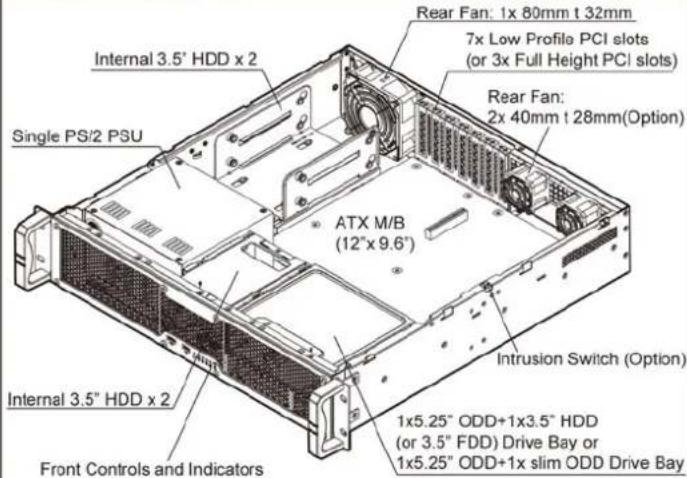
Rear Fan: 1x 80mm t 32mm 7x Low Profile PCI slots (or 3x Full Height PCI slots) Rear Fan: 2x 40mm t 28mm(Option) ATX M/B (12" x 9.6") Single PS/2 PSU Intrusion Switch (Option) 1x5.25" ODD+1x3.5" HDD (or 3.5" FDD) Drive Bay or 1x5.25" ODD+1x slim ODD Drive Bay Internal 3.5" HDD x 2 Front Controls and IndicatorsFront Panel Controls and Indicators
text_image
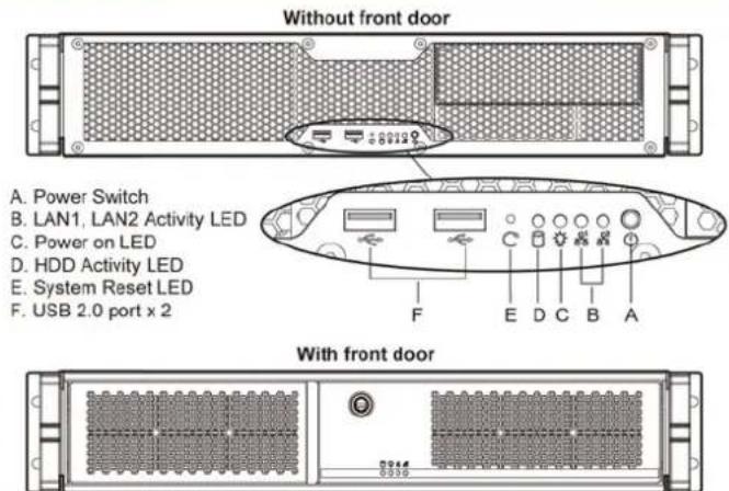
Without front door A. Power Switch B. LAN1, LAN2 Activity LED C. Power on LED D. HDD Activity LED E. System Reset LED F. USB 2.0 port x 2 With front doorMaintaining Front Door Filter
text_image
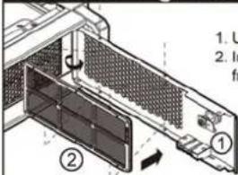
1. U 2. In fr ① ②- Unlock the front door and take out the filters to clean
- Insert two filters on both left and right sides of the front door with four anchoring points
Rear Window Configuration
text_image
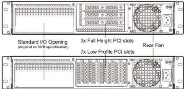
Standard I/O Opening (depend on M/B specification) 3x Full Height PCI slots 7x Low Profile PCI slots Rear FanNotice: Please refer to QIG of RM23608 for installing PCI riser cards.
Top Cover Opening
text_image
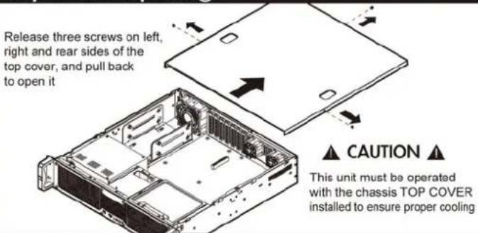
Release three screws on left, right and rear sides of the top cover, and pull back to open it ▲ CAUTION ▲ This unit must be operated with the chassis TOP COVER installed to ensure proper coolingInstalling Internal 3.5" HDD
text_image
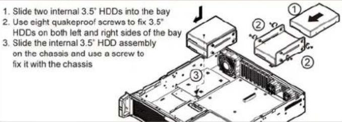
1. Slide two internal 3.5° HDDs into the bay 2. Use eight quakeproof screws to fix 3.5° HDDs on both left and right sides of the bay 3. Slide the internal 3.5° HDD assembly on the chassis and use a screw to fix it with the chassisInstalling PS/2 power supply
text_image
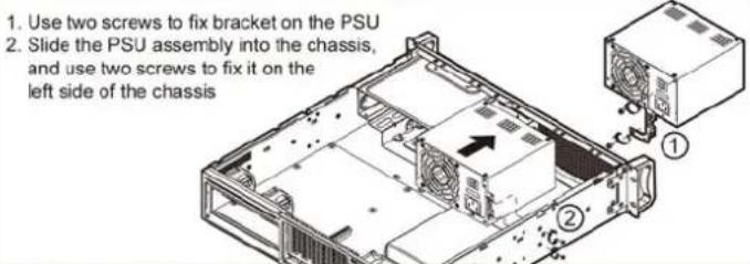
1. Use two screws to fix bracket on the PSU 2. Slide the PSU assembly into the chassis, and use two screws to fix it on the left side of the chassisInstalling Internal 2.5" HDD
text_image
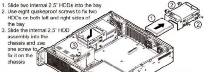
1. Slide two internal 2.5" HDDs into the bay 2. Use eight quakeproof screws to fix two HDDs on both left and right sides of the bay 3. Slide the internal 2.5" HDD assembly into the chassis and use one screw to fix it on the chassisInstalling 5.25"/3.5" Drive Bay(with 3.5" HDD or FDD)
Installing 5.25" ODD
- Release two screws on top of the drive bay to take it out from the chassis
- Release one screw at the right side of the drive bay
- Take out the upper front cover
- Slide the 5.25" ODD into the drive bay assembly
- Use eight screws to fix on both left and right sides of the drive bay
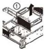
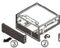
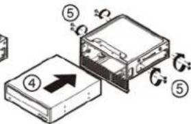
text_image
Diagram showing a device with numbered components and directional arrows indicating motion or assembly.Installing 3.5" HDD
Slide 3.5" HDD into drive bay, and use four quakeproof screws to fix it at the bottom of the drive bay
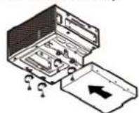
Installing FDD
- Remove the lower front cover of the drive bay
- Slide FDD into drive bay
- Use four screws to fix it on both left and right sides of the drive bay
text_image
Diagram showing three labeled mechanical or electronic components with directional arrows indicating movement or assembly.Installing 5.25"/3.5" Drive Bay
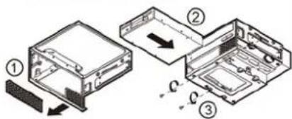
- Slide the 5.25"/3.5" drive bay into the chassis
- Use two screws to fix it on the chassis
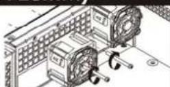
Installing Rear Fan (2 x 40mm t 28mm)
Use two screws to fix the fan assembly (fan+ finger guard) on rear window
Installing Intrusion Switch
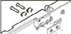
Use two screws to fix the intrusion switch with a bracket on the chassis