RM22300-L - Server Chenbro Micom - Kostenlose Bedienungsanleitung
Finden Sie kostenlos die Bedienungsanleitung des Geräts RM22300-L Chenbro Micom als PDF.


Benutzerfragen zu RM22300-L Chenbro Micom
0 Frage zu diesem Gerät. Beantworten Sie die, die Sie kennen, oder stellen Sie Ihre eigene.
Eine neue Frage zu diesem Gerät stellen
Laden Sie die Anleitung für Ihr Server kostenlos im PDF-Format! Finden Sie Ihr Handbuch RM22300-L - Chenbro Micom und nehmen Sie Ihr elektronisches Gerät wieder in die Hand. Auf dieser Seite sind alle Dokumente veröffentlicht, die für die Verwendung Ihres Geräts notwendig sind. RM22300-L von der Marke Chenbro Micom.
BEDIENUNGSANLEITUNG RM22300-L Chenbro Micom
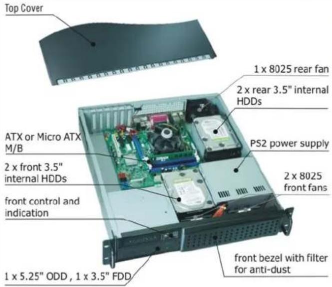
Major Components
text_image
Top Cover 1 x 8025 rear fan 2 x rear 3.5" internal HDDs PS2 power supply ATX or Micro ATX M/B 2 x front 3.5" internal HDDs front control and indication 2 x 8025 front fans 1 x 5.25" ODD , 1 x 3.5" FDD front bezel with filter for anti-dustFront Panel Controls and Indicators
text_image
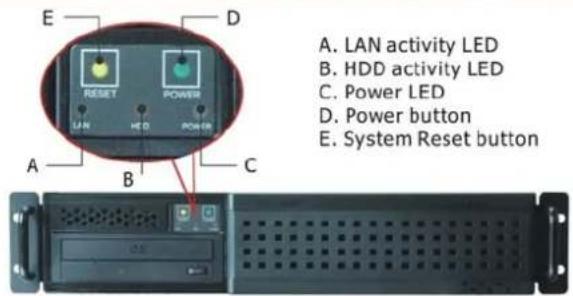
A. LAN activity LED B. HDD activity LED C. Power LED D. Power button E. System Reset buttonRear Window Configuration
text_image
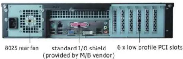
8025 rear fan standard I/O shield (provided by M/B vendor) 6 x low profile PCI slotsTop Cover Opening
text_image
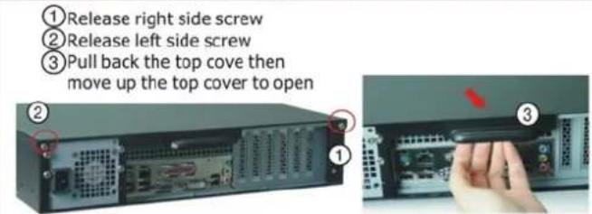
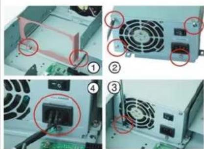
① Release right side screw ② Release left side screw ③ Pull back the top cove then move up the top cover to openPS2 Power Supply Installation
text_image
Four-panel photo showing computer power drive components with red annotations highlighting specific parts in each image.① Release two screws then move out the PSU bracket from chassis bottom
② Attach with four screws to fix the PSU on the PSU bracket
③ Install whole assembly and attach with original two screws to fix
④ Insert three power pins on the AC socket of PSU
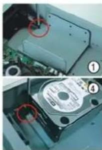
Rear 3.5" Internal HDD (2 pcs) Installation
natural_image
Close-up of a mechanical device showing internal components and a close-up view (no visible text or symbols)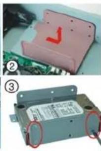
natural_image
Two-panel image showing a pink plastic enclosure with a red checkmark on top, and an electronic device with a label and red ring (no readable text or symbols)① Release one screw
② Slide by arrow sign until hook released then take out the HDD bracket from chassis bottom
③ Attached with 8 pcs screws on the both sides of bracket to fix the two HDDs
④ Slide back and attached with original screw to fix whole HDD bracket on the chassis bottom
Front 3.5" Internal HDD (2 pcs) Installation
natural_image
Two-panel photo showing a computer case with an open drive and a close-up of a battery pack (no visible text or symbols)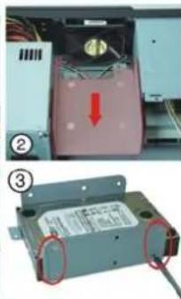
text_image
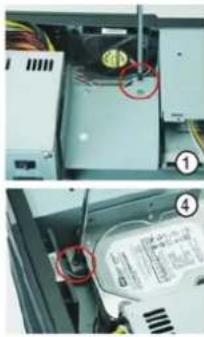
Technical diagram showing a device with labeled components and a red arrow indicating a downward motion or force direction.① Release one screw
② Slide by arrow sign until hook released then take out the HDD bracket from chassis bottom
③ Attached with 8 pcs screws on the both sides of bracket to fix the two HDDs
④ Slide back and attached with original screw to fix whole HDD bracket on the chassis bottom
5.25" / 3.5" Drive Bay Installation
natural_image
Two-panel image showing a device with a red circle highlighting a component, and a close-up of a mechanical part with a red arrow indicating a force or motion (no visible text or symbols)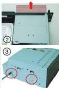
natural_image
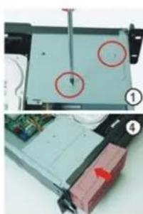
Two views of a printer with a paper feeding into a slot, showing internal components and a red arrow indicating motion (no text or symbols present)① Release two screws on the top side of drive bay
② Pull out the whole drive bay from chassis front site
③ Attached with 4 pcs screws on the both sides of bracket to fix FDD Attached with 8 pcs screws on the both sides of bracket to fix ODD
④ Push back and attached with original two screws on the top side of drive bay
ATX Mother Board Installation
natural_image
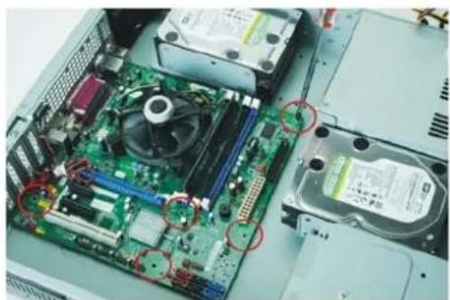
Interior view of a computer motherboard showing CPU socket, RAM slots, and drive bays (no text or symbols visible)① Install M/B and align with mounting hole on the chassis bottom
② Attached with screws to fix M/B on the chassis bottom