
FP2L - Ferngesteuertes spielzeug FUTABA - Kostenlose Bedienungsanleitung
Finden Sie kostenlos die Bedienungsanleitung des Geräts FP2L FUTABA als PDF.


Benutzerfragen zu FP2L FUTABA
0 Frage zu diesem Gerät. Beantworten Sie die, die Sie kennen, oder stellen Sie Ihre eigene.
Eine neue Frage zu diesem Gerät stellen
Laden Sie die Anleitung für Ihr Ferngesteuertes spielzeug kostenlos im PDF-Format! Finden Sie Ihr Handbuch FP2L - FUTABA und nehmen Sie Ihr elektronisches Gerät wieder in die Hand. Auf dieser Seite sind alle Dokumente veröffentlicht, die für die Verwendung Ihres Geräts notwendig sind. FP2L von der Marke FUTABA.
BEDIENUNGSANLEITUNG FP2L FUTABA
Futaba®
DIGITAL PROPORTIONAL
RADIO CONTROL
text_image
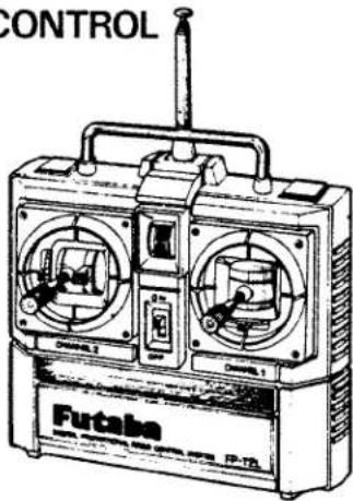
CONTROL Futaba FP-TLINSTRUCTION MANUAL
FP-2L

FUTABA CORPORATION OF AMERICA
FUTABACORPORATION
D60304
FEATURES OF FP-2L
TRANSMITTER FP-T2L
- New stick mechanism. The left-hand stick changes the neutral position in 5 steps by moving the netral lever and is extremely easy to use.
- Level meter tells the state of the battery voltage at a glance.
- Can be easily modified for NiCd battery use.
- All channel survo reverse switches, are very convenient whenever reversing is necessary.
RECEIVER FP-R2GS
- Miniature type, light weight, rugged construction.
- Crystal is replaceable from the outside. (Except "J" Series)
- 3P mini-connectors are compatible with existing sets.
SERVO FP-S28
- New indirect drive/completely sealed potentiometer substantially improves vibration and shock resistance, and neutral accuracy.
- Unique Futaba power-saving custom IC provides high starting torque narrow dead band, and excellent trackability.
- Fiberglass PBT (polybutylene terephthalate) servo case is mechanically strong and is invulnerable to glow fuel.
●Strong polyacetyl resin precision servo gear featuring smooth operation, accurate neutral, and minimal backlash.
- Fiberglass epoxy PC board with THRU-THE-HOLE plating improves the servo amp vibration and shock resistance.
- Thick film gold plated connector pins eliminate the problem of faulty contact, improve reliability against shock and vibration.
- Special pad grommets simplify mounting of the servo, and are extremely vibration-resistant.
● Four kind of special adjustable horn are available.
- High 48.7oz-in (3.5 kg-cm) output torque is perfect for almost all models.
Thank you for buying a Futaba digital proportional radio control set. Please read this manual carefully before using your new set.

FUTABA CORPORATION OF AMERICA
555 West Victoria Street, Compton, Calif. 90220, U.S.A
Phone: 213-537-9610 Telex: 23-0691227 Facsimile: 213-637-8529
FUTABA CORPORATION
Tokyo Office: Daido Bldg. 3-1-16, Sotokanda, Chiyoda-ku, Tokyo, Japan
Phone:(03)255-5881 Telex:J26532
Printed in Japan 84052099
SET CONTENTS AND RATINGS
(Specifications are subject to change without prior notice.)
| FP-2L | |
| Transmitter | FP-T2L |
| Receiver | FP-R2GS |
| Servo | FP-S28x2 |
| Switch, battery holder, etc. |
TRANSMITTER FP-T2L
Operating system: 2 stick (neutral free setting
Transmitting frequency: 27MHz band
Modulation system: AM (amplitude modulation)
Power requirement: 10.5V, AA penlight battery x 7
Current drain: 100mA
RECEIVER FP-R2GS
Receiving frequency: 27MHz band
Intermediate frequency: 455kHz
Selectivity: 3kHz/-3dB
Range: 500m on the ground, 1000m in the air with FP-T2L
Power requirement: 4.0 \~ 6.6V, flashlight battery x 4, shared with servo
Current drain: 6V 10mA
Dimensions: 37 x 53.5 x 19mm
Weight: 38g
SERVO FP-S28
Control system: +pulse width control
Operating angle: Rotary system one-side 45^ or greater (including trim)
Power requirement: 4.8 or 6.0V
(shared with receiver)
Current drain: 6.0V, 8mA (at : dle)
Output torque: 48.7oz-in (3.5kg-cm)
Operating Speed: 0.24 sec/60°
Dimensions: 1.59 x 0.79 x 1.59 inch
(40.5 × 20 × 40.5mm)
Weight: 1.87oz (53g)
* Subject to change without notice.
HANDLING THE TRANSMITTER FP-T2L
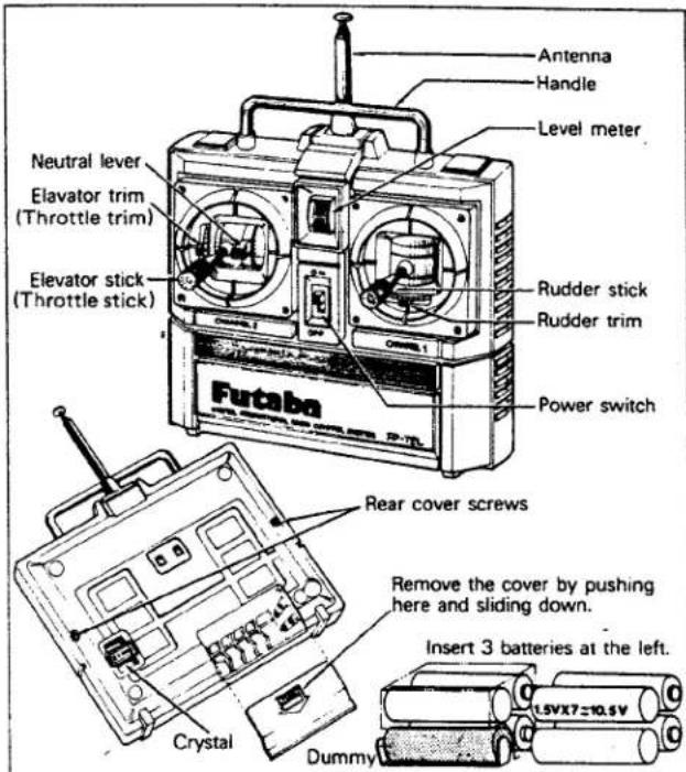
- The below figures show the names of each part of the transmitter. Memorize the names and functions before using your set.
- Remove the battery cover on the rear of the set and load the 7 penlight batteries as shown in the figure, being sure that the polarities are correct.
- Extend the antenna fully and set the power switch to ON. The pointer of the level meter should deflect to the green zone. If it does not deflect, or deflects very little, check the batteries and their connections and polarity.
- If the level meter pointer deflects to the red zone, the receiving range will be short. Therefore, replace the batteries whenever the pointer drops to the boundary between the red and green zones.
- The trim lever fine adjusts the rudder. Use it for neutral adjustment and to correct the flying posture after mounting of the mechanism. After test flight, keep the trim lever in the neutral position as much as possible and adjust pushrod linkage for correction.
●The neutral position of the left-hand elevator stick (engine control stick) can be selected in 5 steps by shifting the neutral lever as shown in the figure. Adjust it to match the particular applications. - Replace the crystal by removing the crystal holder at the rear of the transmitter. AM, crystal, transmitter (T), receiver (R).
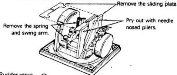
●The elevator stick is a self-neutral type. To change it to a ratchet type, remove th sliding plate as illustrated in the figure, then remove the spring and swing arm.
HANDLING THE FP-R2GS RECEIVER AND FP-S28 SERVO
- Load the four penlight batteries into the battery holder in the correct polarity, and tighten the cover coin screw.
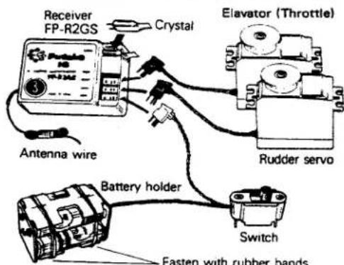
- Connect the servo and switch securely as illustrated in the figure. Then extend the transmitter and receiver antenna fully.
- Set the transmitter power switch to ON; then set the receiver switch to ON.
The servo stops near the neutral position.
Operate the transmitter sticks and check that the servos faithfully follow movement of the sticks.
- Set the pushrod at each servo horn and check that the direction of operation of each rudder coincides with that of the transmitter controls.
- Operate each servo horn over its operating range, being sure that the pushrods do not bind or bend.
Applying unreasonable force to the servo horn will adversely affect the servo and quickly drain the batteries. Be sure the operating range of the rudder is larger than the fully stroke (including the trim component) of the servo travel. Mount servos so that the servo horns of each servo move smoothly and do not interfere with each other even when the trim lever and stick lever are operated in the same direction simultaneously.
●Pay careful attention to noise.
Intermittent contact of metal parts due to engine vibration, etc. will generate noise and cause the receiver servos to operate erroneously.
We recommend the use of noiseless parts.
- When installing the switch harness, drill a rectangular hole somewhat larger than the full stroke of the switch knob and mount the switch so that it can be turned ON and OFF smoothly and positively. This also applies when the switch is mounted in the fuselage and turned ON and OFF
text_image
Antenna Handle Level meter Neutral lever Elavator trim (Throttle trim) Elevator stick (Throttle stick) Rudder stick Rudder trim Power switch Futaba Rear cover screws Remove the cover by pushing here and sliding down. Insert 3 batteries at the left. Crystal DummyModification from self-neutral to ratchet
text_image
Remove the spring and swing arm. Remove the sliding plate. Pry out with needle nosed pliers.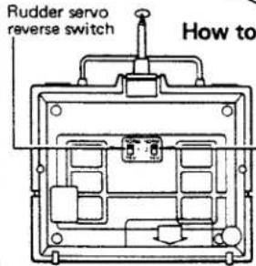
text_image
Rudder servo reverse switch How toAll the switches shown are in normal positions at upper side of switch. Each servo reverse switch is to reverse direction of servo.
Throttle servo reverse switch
After completion of assembly, if servo moves to opposite direction against transmitter stick movement, apply servo reversing switch.
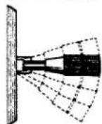
Neutral lever operation
The neutral position of the stick lever can be adjusted in 5 steps as illustrated in the figure by moving the neutral lever.
text_image
Receiver FP-R2GS Crystal Antenna wire Battery holder Switch Fasten with rubber bands Elavator (Throttle) Rudder servofrom the outside with wire, etc. Mount the switch where it will not come into direct contact with engine oil, dust, etc.
● Never cut the receiver antenna; even though it may seem too long.
- When using the receiver and servos in a boat or automobile, waterproof and dustproof the radio compartment. After use, open the radio compartment to prevent condensation.
text_image
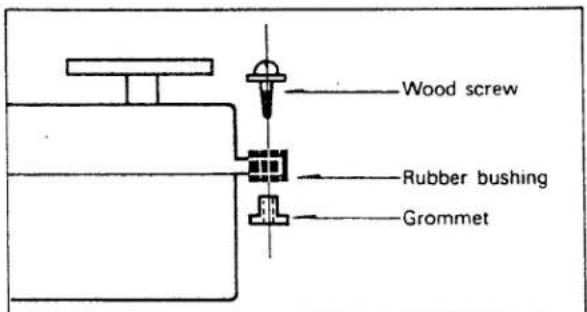
Wood screw Rubber bushing Grommet- After mounting and checking each part, range check the system by extending the transmitter to its shortest length and the receiver antenna to its full length. The model should operate at a distance of 20 30m . The rudders (servos) should faithfully follow the operations performed at the transmitter.
●The crystal can be changed from outside the receiver case. Always use Futaba pair crystals. - Install the servos securely. Use servo trays for easy and convenient installation of servo. When installing the servo directly to wood, use an eyelet and flat washers as illustrated in the figure.
●A spare horn is supplied with the set. Use it as needed.
●Pack the receiver in sponge rubber and wrap the rubber with rubber bands.
Mount the receiver at the center where it will not be affected by engine vibrations and will not directly touch the fuselage.
- If the receiver is to be used near water, such as in a boat or seaplane, waterproof it by placing it in a plastic bag and sealing the mouth of the bag with rubber bands. After use, immediately remove the receiver from the bag to prevent condensation.
- Also pack the receiver and servo batteries in sponge rubber and wrap the sponge with rubber bands. When used in an airplane, shifting of the batteries will change the center of gravity of the plane. After positioning the batteries, fasten them securely. Waterproof the connectors in the same manner as the receiver.
- Fasten the servo and switch leads with the same rubber bands used to wrap the receiver.
● Futaba three-wire servos can be used with any Futaba transmitter and receiver combination. (Except "J" series) - After mounting and checking all the parts, take your set to your hobby dealers, or an experienced radio control enthusiast, and ask them to inspect it and explain the handling and precautions for radio control models.
- To enjoy your radio control model to the fullest, always follow the instructions of an experienced radio control enthusiast and strictly obey all safety regulations.
MODIFICATION TO NICKEL-CADMIUM BATTERY
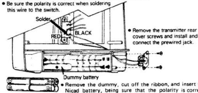
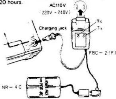
●Using the Futaba FBPK-4 (L Series NiCd battery charger set), modify the transmitter power supply as shown in the figure.
● A nickel-cadmium battery (NR4C) can be used as the receiver and servo power supply without any modification.
text_image
Be sure the polarity is correct when soldering this wire to the switch. Solder RED BLACK Remove the transmitter rear cover screws and install and connect the prewired jack. Dummy battery Remove the dummy, cut off the ribbon, and insert the Nicad battery, being sure that the polarity is corre- Remove the transmitter rear cover blind plate and install the cover with the screws.
- Normally, charge the battery for about 15 hours. If the battery has not been used for a long time, charge it for 20 hours.
text_image
20 hours. AC110V (220V - 240V) Charging jack Rx Tx FBC - 2 (F) NR - 4 CHandling the nickel-cadmium battery
Since the battery contact may be faulty when the battery cannot be charged, or discharges quickly, remove the battery from the battery holder and wipe the (+) and (−) contact surfaces shown in the figure with a dry cloth (do not use an organic solvent, etc.). To prevent malfunctions due to faulty battery contact, it is suggested that the battery be removed and cleaned about once every 1 to 2 months.
(Note) Because the battery contact surfaces are made of nickel plated iron, do not clean them with a file, sandpaper, etc.; otherwise the surfaces may rust.
GUARANTEE
Your NEW FUTABA Digital Proportional R/C system is guaranteed against defects in workmanship and material for 180 days from the date of purchase when the attached registration card is returned to us within ten days of purchase.
This Guarantee is null and void if the R/C system has been improperly handled, damaged in a crash, or tampered with and does not cover the replacement of plastic housings or electronic components damaged due to the use of improper voltages.
When service is required, please take your equipment to your local authorized service station or ship it directly to us. All postage, shipping, and insurance charges must be paid by the user.
Futaba Digital Proportional Frequencies (FOR U.S.A.)
Frequency Channel No. Flag Color
| 26-27MHz · Aircraft/Car/Boat | 75MHz · Car & Boat only | ||||
| 26.995 | - | Brown | 75.430 | 62 | Blue-Red (Top Flag/Ribbon-BottomFlag/Ribbon) |
| 27.045 | - | Red | |||
| 27.095 | - | Orange | 75.470 | 64 | Blue-Yellow |
| 27.145 | - | Yellow | 75.510 | 66 | Blue-Blue |
| 27.195 | - | Green | 75.550 | 68 | Blue-Grey |
| 27.255 | - | Blue | 75.590 | 70 | Purple-Black |
| 75.670 | 74 | Purple-Yellow | |||
| 72/75MHz · Aircraft only *Shared | 75.710 | 76 | Purple-Blue | ||
| 72.030 | 12 | Brown-Red (Top Flag/Ribbon-BottomFlag/Ribbon) | 75.750 | 78 | Purple-Grey |
| 75.790 | 80 | Grey-Black | |||
| 72.080 | - | White/Brown | 75.830 | 82 | Grey-Red |
| 72.160* | - | White/Blue | 75.870 | 84 | Grey-Yellow |
| 72.240 | - | White/Red | |||
| 72.320* | - | White/Purple | 53MHz · Aircraft/Car/Boat - FCC Amatuer License Required | ||
| 72.400 | - | White/Orange | 53.100 | -- | Black/Brown |
| 72.550 | 38 | Orange-Grey | 53.200 | -- | Black/Red |
| 72.590 | 40 | Yellow-Black | 53.300 | -- | Black/Orange |
| 72.630 | 42 | Yellow-Red | 53.400 | -- | Black/Yellow |
| 72.670 | 44 | Yellow-Yellow | 53.500 | -- | Black/Green |
| 72.710 | 46 | Yellow-Blue | |||
| 72.750 | 48 | Yellow-Grey | |||
| 72.790 | 50 | Green-Black | 53.600 | -- | Black/Blue |
| 72.830 | 52 | Green-Red | 53.700 | -- | Black/Purple |
| 72.870 | 54 | Green-Yellow | 53.800 | -- | Black/Grey |
| 72.910 | 56 | Green-Blue | |||
| 72.960* | - | White/yellow | |||
| 75.640 | - | White/Green | |||
| 26.995 | - | Brown |
| 27.045 | - | Red |
| 27.095 | - | Orange |
| 27.145 | - | Yellow |
| 27.195 | - | Green |
| 27.255 | - | Blue |
72/75MHz - Aircraft only *Shared
| 72.030 | 12 | Brown-Red (Top Flag/Ribbon-Bottom Flag/Ribbon) |
| 72.080 | - | White/Brown |
| 72.160* | - | White/Blue |
| 72.240 | - | White/Red |
| 72.320* | - | White/Purple |
| 72.400 | - | White/Orange |
| 72.550 | 38 | Orange-Grey |
| 72.590 | 40 | Yellow-Black |
| 72.630 | 42 | Yellow-Red |
| 72.670 | 44 | Yellow-Yellow |
| 72.710 | 46 | Yellow-Blue |
| 72.750 | 48 | Yellow-Grey |
| 72.790 | 50 | Green-Black |
| 72.830 | 52 | Green-Red |
| 72.870 | 54 | Green-Yellow |
| 72.910 | 56 | Green-Blue |
| 72.960* | - | White/yellow |
| 75.640 | - | White/Green |
| 53MHz - Aircraft/Car/Boat - FCC Amatuer License Required | ||
| 53.100 | - | Black/Brown |
| 53.200 | - | Black/Red |
| 53.300 | - | Black/Orange |
| 53.400 | - | Black/Yellow |
| 53.500 | - | Black/Green |
| 53.600 | - | Black/Blue |
| 53.700 | - | Black/Purple |
| 53.800 | - | Black/Grey |
- The frequency of Futaba digital proportional sets can be changed among bands (1) \~ (6) on the 27MHz band only.
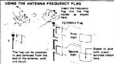
● However, a 27MHz band set cannot be changed to 72MHz band, and vice versa. - Therefore, always attach the correct frequency flag to the end of the transmitter antenna. Each frequency band has its own designated color, as stated in the left. The
frequency flag is intended for identification purposes.
- Also change the frequency flag when frequency is changed.
- Futaba paired crystals are precisely matched. Always use a Futaba crystal set (transmitter, receiver) when changing the frequency.
- It is illegal to change crystals of transmitter on the 72-75MHz bands in the U.S.A.
FOR OTHER MARKETS, FOLLOWING FREQUENCIES ARE AVAILABLE.
| FP-2L | ||
| AM | FM | |
| 27MHz Band | ○ | X |
| 29MHz Band | ○ | X |
| 35MHz Band | ○ | X |
| 40MHz Band | ○ | X |
| 53/60MHz Band | X | X |
| 72/75MHz Band | ○ | X |
The authorized frequencies on each countries are as follows:
| England . . . . . . . .27 & 35MHz AM and FM |
| Sweden. . . . . . . .27 & 35MHz AM and FM |
| Scandinavian countries . . .27, 35 and 40MHz AM/FM |
| Australia | 29MHz |
| U.S.A. | 27 & 72MHz (amonly) |
text_image
USING THE ANTENNA FREQUENCY FLAG Insert the frequency flag into the flag holder as shown here. 72/15MHz Flag First digit Second digit Stable or glue with cyano-alkylate ribbon here. The flag can be attached to and removed from the end of the antenna with one touch.Splined Horn
This horn permits shifting of the servo neutral position at the servo horn. Setting and shifting the neutral position
a) Angle divisions
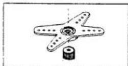
1) The splined horn has 25 segments. The amount of change per segment is: 360 ÷ 25 = 14.4^
2) The minimum adjustable angle is determined by the number of arms or number of the hoies. For four arms, the minimum adjustable angle is:
$$ 3 6 0 ^ {\circ} \div \frac {(2 4 \times 4)}{\text { Number of divisions }} = 3. 6 ^ {\circ} $$
b) Effect
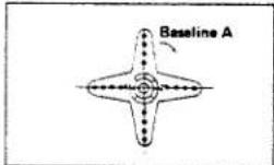
To shift the holes center line to the right (clockwise) relative to baseline A, shift arm 2 to the position of arm 1 and set it to the position closest to baseline A.
[Example] For a four arm horn, the angular shift per segment is 14.4^ . The shift to the right is 90^ - (14.4 × 6) = 3.6^
To shift by the same angle in the opposite direction, use the opposite arm number.
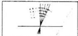
For a six arm horn, turn the arm counterclockwise and set arm 2 to the position of arm 1. The adjustable angle is 60^ - (14.4 × 4) = 2.4^ . Arm 3 shift 4.8^ to the right, arm 6 shifts 2.4^ to the left, and arm 4 shifts 7.2^ to the right and left.
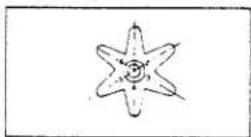


horn A (FSH-6X)

horn B (FSH-6S)
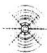
horn C (FSH-6R)

horn D (FSH-6W)
text_image
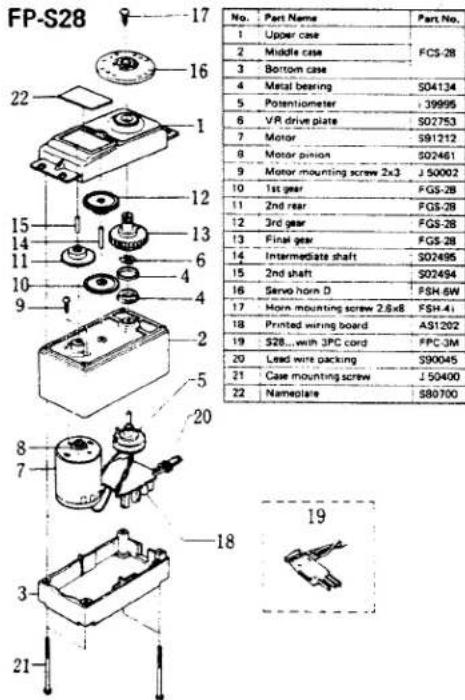
FP-S28 17 16 22 1 15 14 11 10 9 2 5 20 8 7 3 21 12 13 6 4 4 16 No. Part Name Part No. 1 Upper case FCS-28 2 Middle case 3 Bottom case 4 Metal bearing S04134 5 Potentiometer 39995 6 VR drive plate S02753 7 Motor S91212 8 Motor pinion S02461 9 Motor mounting screw 2x3 J S00002 10 1st gear FGS-28 11 2nd rear FGS-28 12 3rd gear FGS-28 13 Final gear FGS-28 14 Intermediate shaft S02495 15 2nd shaft S02494 16 Servo horn D FSH-6W 17 Horn mounting screw 2.8x8 FSH-41 18 Printed wiring board AS1202 19 S28...with 3PC cord FPC-3M 20 Lead wire packing S90045 21 Case mounting screw J S04000 22 Namovlar S80700REPAIR SERVICE
- When requesting repair of trouble that has occurred suddenly of from long use, describe the trouble symptoms in as much detail as possible.
This will facilitate detection of the trouble point and shorten the repair period greatly. - Defects caused by faulty materials or workmanship will be corrected free of charge.
- This limited warranty is null and void if the set has been tampered with or disassembled. Refer to warranty statement for details.
WORLD SALES & SERVICE FACILITIES:
Australia: FUTABA SALES AUSTRALIA PTY. LTD., MELBOUÈNE, TEL: 211-4788
Argentina: MODELISMO AERONAUTICO DEGA SRL BUENOS ALBES TEL 293-2299
Canada: UDISCO LTD, MONTREAL TEL: 481-8109
Chile: HOBBY LANDIA, SANTIAGO TEL. 743957
Denmark: FUTABA IMPORT DENMARK, COPENHAGEN TEL. 02-91-01-01
England: RIPMAX LIMITED. LONDON TEL 01-8048272
Finland: NORSS OLYNELSINKLI TEL 09-530214
Finland: NORES OY; HELSINKT TEL 90-5203
Greece: C.&G. MACHIYIANNIS CO., PIRAEUS
TEL: 021-4175191
Hong Kong: RADAR CO. LTD. TEL: 3-680507
Italy: R.C.S. RADIO CONTROL SYSTEM, CREMONA
TEL: 0372-20588
Lebanon: KHAIRALLAH MODELCRAFT, BEIRUT TEL: 226-681
New Zealand: AMALGAMATED WIRELESS (AUSTRALIA)
N.Z. LTD., WELLINGTON TEL. 58-979
Norway: MODEL HOBBY A/S, OSLO TEL: 442015
Singapore: SINGAPORE HOBBY SUPPLIES TEL: 430337
South Africa: REDIPAK (PTY.) LTD., JOHANNESBURG
TEL: 211511
Spain: HOBBY & TOY INTERNATIONAL. LAS PALMAS
TEL: 216930
Sweden: RADIO CONTROL CENTER, JONKOPING
TEL: 226-145360
U.S.A.: FUTABA CORPORATION OF AMERICA, CALIFORNIA, TEL. 213.537.9610
W. Germany: ROBBE MODELLSPORT GMBH. GREBENHAIN TEL 06644 7041