
FP2PBK - Ferngesteuertes spielzeug FUTABA - Kostenlose Bedienungsanleitung
Finden Sie kostenlos die Bedienungsanleitung des Geräts FP2PBK FUTABA als PDF.


Benutzerfragen zu FP2PBK FUTABA
0 Frage zu diesem Gerät. Beantworten Sie die, die Sie kennen, oder stellen Sie Ihre eigene.
Eine neue Frage zu diesem Gerät stellen
Laden Sie die Anleitung für Ihr Ferngesteuertes spielzeug kostenlos im PDF-Format! Finden Sie Ihr Handbuch FP2PBK - FUTABA und nehmen Sie Ihr elektronisches Gerät wieder in die Hand. Auf dieser Seite sind alle Dokumente veröffentlicht, die für die Verwendung Ihres Geräts notwendig sind. FP2PBK von der Marke FUTABA.
BEDIENUNGSANLEITUNG FP2PBK FUTABA
INSTRUCTION MANUAL

text_image
BEC BATTERY ELIMINATOR CIRCUITRY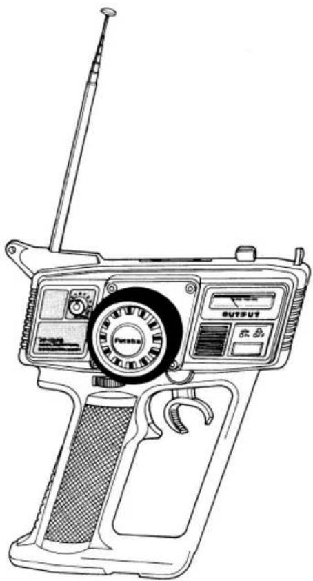
natural_image
Line drawing of a vintage handheld device with control panel and antenna (no text or symbols)FP-2PB
natural_image
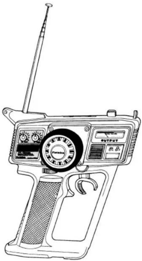
Line drawing of a portable radio device with control panel and antenna (no text or symbols)FP-2PBK
natural_image
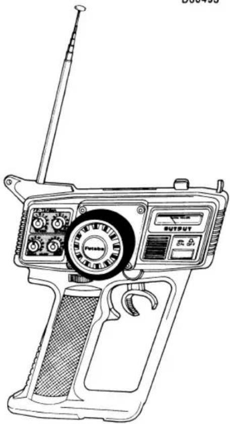
Line drawing of a vintage manual gun device with control panel and trigger (no text or symbols)FP-2PBKA
FP-2PB
FP-2PBK
FP-2PBKA
- FP-2PB/2PBK/2PBKA is a high performance 2 channel digital proportional R/C set and has built-in BEC (Battery Eliminator Circuitry) system.
Since the power of receiver and servo power is supplied from the running Nicd battery, there is no troublesome wiring and the vehicle can be made lighter.
Thank you for puchasing a Futaba digital proportional radio control set. Please read this manual carefully before using your set.
CONTENTS
FEATURES 1
COMPOSITION AND RATINGS 1
TRANSMITTER FP-T2PB/T2PBK/T2PBKA 2
LOADING THE PENLIGHT BATTERIES.... 5
CRYSTAL REPLACEMENT 5
STEERING TRIMMER ADJUSTMENT 6
RECEIVER AND SERVOS 7
FOR ELECTRIC MOTOR CAR 9
DIGITAL PROPORTIONAL FREQUENCIES (FOR USA) 10
CONVERSION TO NICAD SYSTEM FP-2PBKA ONLY 11
SERVO FP-S148 FP-S9601 12
GUARANTEE/REPAIR SERVICE 12
FP-S132H WHEN NOT RUNNING.... 13
SPLINED HORN 13
FEATURES OF FP-2PB/2PBK/2PBKA
FP-2PB/2PBK/2PBKA has a BEC function
●The BEC (Battery Eliminator Circuitry) system is a high performance constant voltage circuit (regulator). Since the running Nicd battery can also be used as the receiver servo power supply, there is no troublesome wiring and the vehicle can be made lighter.
●The FP-2PB/2PBK/2PBKA is the highest class pistol grip type AM 2 channel digital proportional R/C set.
TRANSMITTER
- Newly designed cockpit type control panel.
- Easy to use size and design based on human engineering.
- Mechanical ATL (Adjustable Throttle Limiter) on throttle trigger. Because the reverse (brake) stroke of the throttle trigger can be mechanically varied continuously, reverse (brake) linkage is easy.
- Throttle ATV
The throttle servo travel volume can be adjusted and set with two trimers, independently. (FP-T2PBKA)
- Steering rate adjuster. The left and right servo throws can be adjusted simultaneously even while running (T2PBK/T2PBKA)
- Servo reverse switches (steering & throttle). Since each servo can be switched between forward and reverse from the outside of the transmitter, linkage hookup is extremely easy.
- Level meter shows the state of the battery at a glance.
• Crystal can be changed from the outside. (Except 72/75 MHz)
RECEIVER FP-R112JE
● High performance AM 2 channel receiver with BEC in which miniature size and light weight have been achieved by using integrated circuits. (20% thinner and 20% lighter than the FP-R102JE)
- New RF circuit improves intermodulation interference substantially.
● Futaba full custom IC improves reliability considerably.
● Newly designed case is easy to install.
● High performance BEC system allows use with power supply voltages up to 8.4 V.
RECEIVER FP-R102H
- Small, lightweight, and rugged high-performance 2-channel AM receiver miniaturized by careful use of the space between components on the PC board.
- Connector w/lead wire comes out from the same side so that waterproofing and mounting in the model are easy.
•FUTABA custom IC decoder increases reliability. - New type miniature high reliability crystal socket pins increase reliability and allow replacement of the crystal from the outside of the receiver.
- Thick film gold plated connector pins eliminate poor contact and improve reliability against shock.
SERVO FP-S148, S9601, S132H HIGH NEUTRAL LOW PROFILE SERVO
- Vibration and shock resistance have been improved further by using a direct wiring system which directly connects the servo amp, motor and potentiometer. (S148, S9601)
- The height of the servo has been reduced and high torque, high speed, and smooth movement equal to that of the coreless servo have been realized by using a new small, high-performance motor. (Output torque 42 oz-in <3 kg-cm> operating speed 0.22 sec/60°). (S148)
- New indirect drive/completely sealed potentiometer substantially improves vibration and shock resistance, and neutral accuracy.
- Unique Futaba power-saving custom IC provides high starting torque narrow dead band, and excellent trackability.
- Fiberglass PBT (polybutylene terephthalate) servo case is mechanically strong and is invulnerable to glow fuel.
- Strong polyacetyl resin precision servo gear featuring smooth operation, accurate neutral, and minimam backlash.
- Fiberglass epoxy PC board with THRU-THE-HOLE plating improves the servo amp bivration and shock resistance.
- Thick placted connector pins eliminate the problem of faulty contact, improve reliability against shock and vibration, and prevent reverse insertion.
- Special pad grommets simplify mounting of the servo, and are extremely vibration-resistant.
- Seven kind of special adjustable horns are available.
- High 42 oz-in (3kg-cm) output torque is perfect for almost all models. (S148)
- High operating speed of 0.13 sec/60° makes it perfect when especially high speed is necessary. (S132H)
● High quality double ball bearing servos using the highest quality coreless motor. Output torque 33.3 oz-in (2.4 kg-cm)
Nominal operating speed 0.15 sec/60° (S9601)
COMPOSITION AND RATINGS
●COMPOSITION
| FP-2PB | FP-2PBK | FP-2PBKA | |
| Transmitter | FP-T2PB x 1 | FP-T2PBK x 1 | FP-T2PBKA x 1 |
| Receiver | FP-R112JEx 1 | FP-R112JEx 1 | FP-R112JEx 1 or FP-R102H x 1 |
| Servo | FP-S148 x 2 | FP-S148 x 2 | FP-S148 x 2, FP-S9601 x 2 or FP-S132H x 2 |
| Battery holder | R2-BSS · N | ||
| Others | Switch, frequency flag, spare horn | ||
●RATINGS
| TRANSMITTER FP-T2PB/T2PBK/T2PBKA | |
| Operating system | Pistol grip, wheel type |
| Transmitting frequency | 27 MHz band, 75 MHz band |
| Modulation type | AM (Amplitude Modulation) |
| Power requirement | 12.0 V, penligh battery x 8 |
| Current drain | 170 mA |
| RECEIVER FP-R112JE | |
| Receiving frequency | 27 MHz band, 75 MHz band |
| Intermediate frequency | 455 kHz |
| Power supply voltage | 4.8 V to 8.4 V (built-in BEC) |
| Current drain | 8.4 V/10 mA, 4.8 V/30 mA (no signal) |
| Dimensions | 1.87 x 1.24 x 0.62 in (47.6 x 31.5 x 15.7 mm) (excluding protruding parts and antenna) |
| Weight | 0.72 oz (20.5 g) |
| Receiving range | 330 yards (300 m) on the ground when FP-T2PBK used (At the best conditions) |
| RECEIVER FP-R102H | |
| Receiving frequency | 27MHz, 75MHz bands |
| Intermediate frequency | 455KHz |
| Receiving range | 150m on the ground using the FP-T2PBKA |
| Power requirement | 4.8V or 6.0V (shared with servos) |
| Current drain | 6V, 11mA |
| Dimensions | 1.09x1.52x0.66 in.(27.8x38.8x16.9mm) |
| Weight | 0.77 oz (22g) (27MHz)0.80 oz (23g) (75MHz) |
| SERVO FP-S146 | |
| Control system | +pulse width control |
| Operating angle | One side 45° or more |
| Power requirement | 4.8 V – 6 V |
| Current drain (IDLE) | 6.0 V, 8 mA (at idle) |
| Output torque | 42 oz. in. (3 kg·cm) |
| Operating speed | 0.22 sec/60° |
| Dimensions | 1.59 x 0.77 x 1.4 in.(40.4 x 19.8 x 36 mm) |
| Weight | 1.56 oz. (44.4 g) |
Ratings are subject to change without prior notice.
| SERVO FP-S132H | |
| Operating system | Pulse width control, 1.520 s neutral |
| Operating angle | Rotary type, one side 40° or greater (including trim) |
| Power requirement | 4.8 or 6.0V (shared with receiver) |
| Current drain | 6.0V, 8mA (at idle) |
| Output torque | 25.02 oz-in (1.8 kg-cm) |
| Operating speed | 0.13 sec/60° |
| Dimensions | 1.46x0.71x1.20 in (37x18x30.5 mm) |
| Weight | 1.13 oz (32g) |
| SERVO FP-S9601 | |
| Control system | *pulse width control 1520 =s neutral |
| Operating angle | One side 45° min (including trim) |
| Power supply | 6.0 V, shard with receiver |
| Current drain | 6.0 V 12mA (at idle) |
| Output torque | 33.3 oz-in (2.4 kg-cm) |
| Operating speed | 0.15 sec/60' |
| Dimensions | 1.22x0.63x1.19 in (31x16x30.2 mm) |
| Weight | 1.09 oz (31g) |
TRANSMITTER FP-T2PB/T2PBK/T2PBKA
• Nomenclature
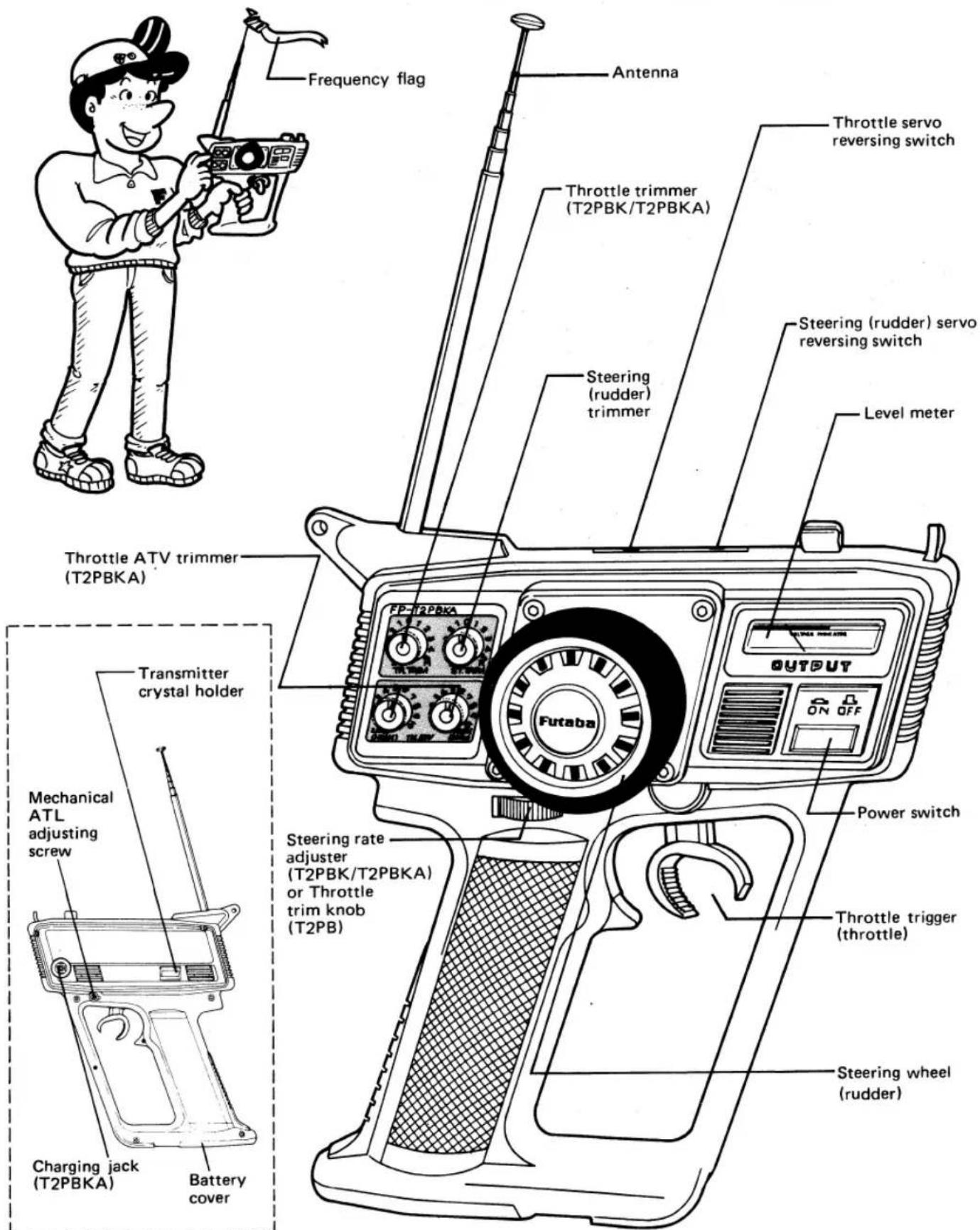
- The name of each part of the transmitter is shown in the figure. Learn them before operating your set.
When running the vehicle, extend the antenna fully.
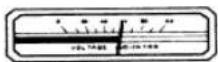
Before using the set, check the remaining battery capacity by checking the level meter.
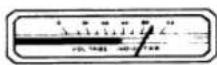
Good
Caution
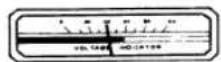
No good
Change the battery.
text_image
Frequency flag Antenna Throttle servo reversing switch Throttle trimmer (T2PBK/T2PBKA) Steering (rudder) servo reversing switch Steering (rudder) trimmer Level meter Throttle ATV trimmer (T2PBKA) Transmitter crystal holder Mechanical ATL adjusting screw Charging jack (T2PBKA) Battery cover Steering rate adjuster (T2PBK/T2PBKA) or Throttle trim knob (T2PB) Power switch Output Futaba Throttle trigger (throttle) Steering wheel (rudder)▲ The servo reversing switches are assumed to be in the normal position in the descriptions below. When the reversing switches are in the reverse position, servo operation is the opposite of that described here.
- Steering wheel (rudder) Steering (rudder) operation.
- Throttle trigger (throttle lever) Engine control/motor control operation.
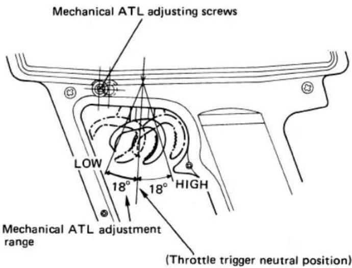
Mechanical ATL (Adjustable Throttle Limiter) adjusting screws
- Mechanical ATL allows mechanical setting of the reverse (brake) stroke of the throttle trigger.
- Loosen this screw with a small Phillips screwdriver and set the throttle trigger to the desired reverse (brake) stroke, then retighten the screw.
- Because the reverse (brake) stroke is continuously variable, reverse side linkage is easy. The adjustment range is 0 to 100% of the reverse stroke.
text_image
Mechanical ATL adjusting screws LOW 18° 18° HIGH Mechanical ATL adjustment range (Throttle trigger neutral position)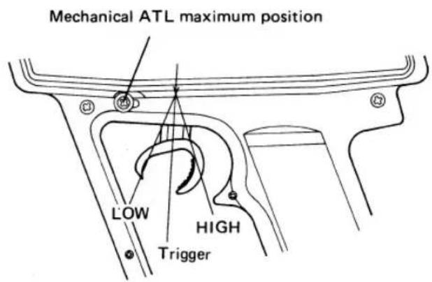
text_image
Mechanical ATL maximum position LOW HIGH Trigger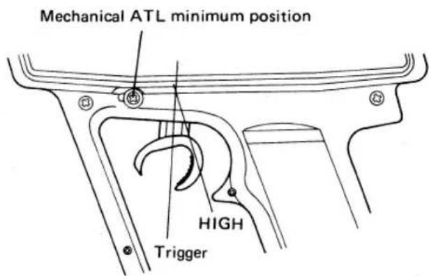
text_image
Mechanical ATL minimum position HIGH Trigger
The throttle trigger can be operated over its full stroke. The throttle servo operates as shown in the figure.

The throttle trigger can be operated only at the high side of the neutral position. The throttle as shown in the figure.
The throttle trigger reverse (brake) stroke can be adjusted over this range with the mechanical ATL adjusting screws.
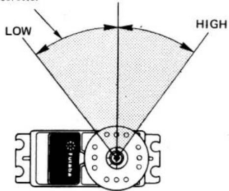
text_image
LOW HIGHThrottle servo
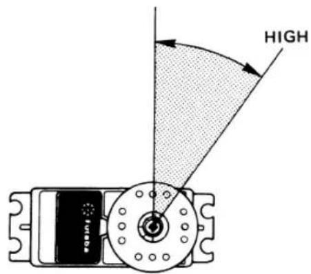
text_image
HIGHThrottle servo
• Steering (rudder) trimmer
Steering (rudder) fine adjustment.
• Steering rate adjuster (T2PBK/T2PBKA)
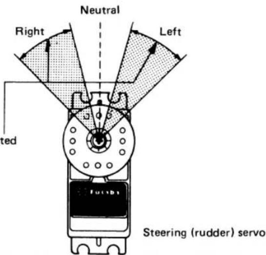
The steering servo deflection angle can be freely set as shown in the figure with this ratchet type adjuster. It is installed where the deflection angle can be easily adjusted to match the course even while running.
The deflection angle can be adjusted within this range, 30%–100%. : Only for FP-T2PBK/T2PBKA
text_image
Neutral Right Left tted Steering (rudder) servo- Throttle trimmer
Throttle (engine control) fine adjustment.
- Steering (rudder) servo reversing switch
Reverses the direction of operation of the steering servo.
- Throttle servo reversing switch
Reverses the direction of operation of the throttle servo.
| The positions of the servo reversing switches are:Left side (NORM): NormalRight side (REV): Reverse | |
| NORM REV | NORM REV |
| Throttle servoreversing switch | Steering (rudder) servoreversing switch |
- Power switch
When this switch is pressed once, the power is turned on and the pointer of the level meter deflects. When the switch is pressed again, the power is turned off.
- Throttle ATV trimmer
ATV... Adjustable Travel Volume.
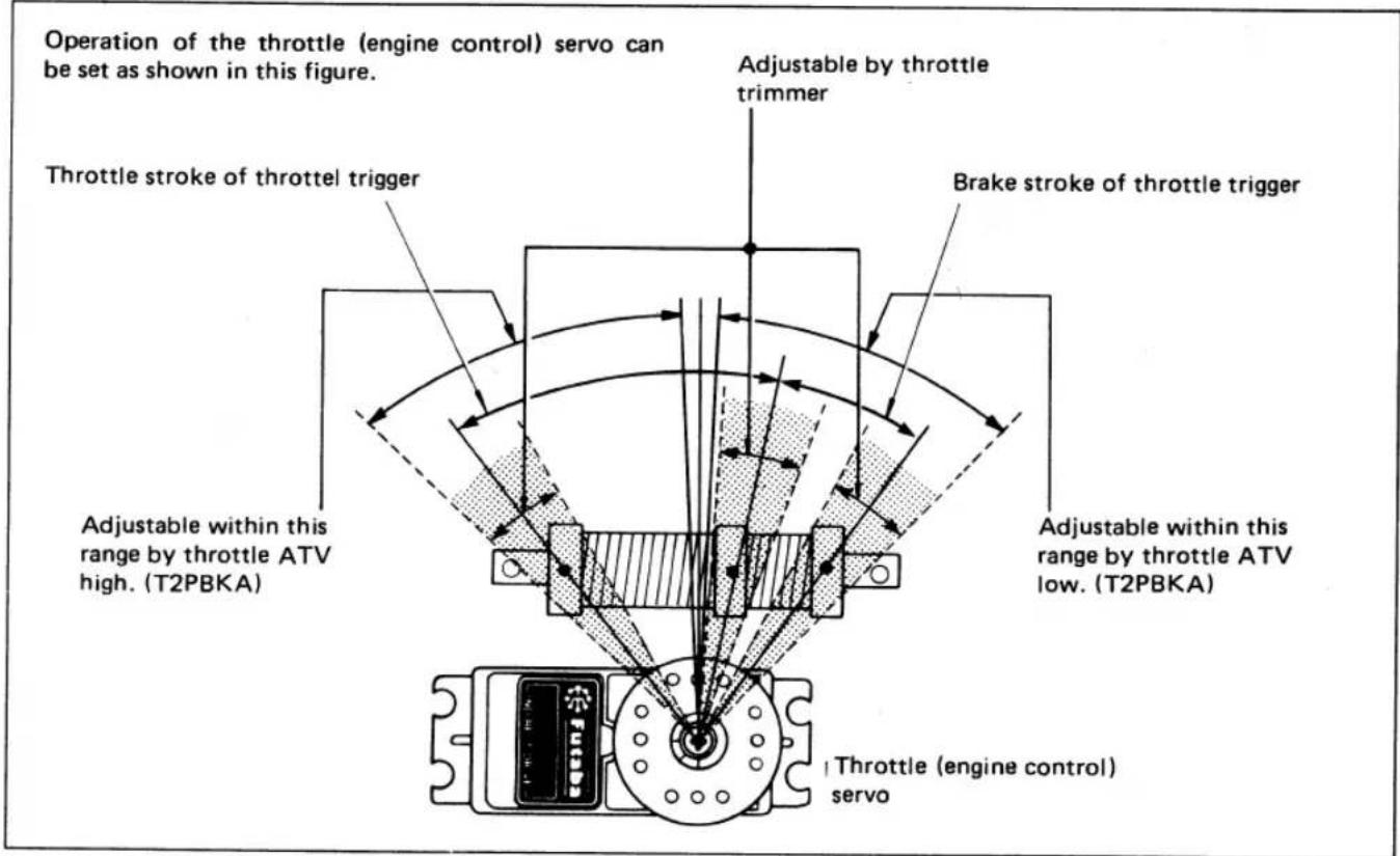
Throttle ATV is a device which permits independent adjustment of the throttle servo left and right sides (from neutral) as shown in this figure with trimmers Low (High) and High (Low). (FP-T2PBKA)
ATV is the abbreviation for Adjustable Travel Volume and is an extremely convenient device by which steering servo travel volume can be adjusted freely with two trimmers prouded.
The relationship between two trimmers does not change even when servo is reversed.
: Only for FP-T2PBKA.

text_image
LOW (HIGH) TH.ATV HIGH (LOW) Futaba INDIRECT DRIVE Futaba INDIRECT DRIVE Throttle Servo▲LOADING THE PENLIGHT BATTERIES
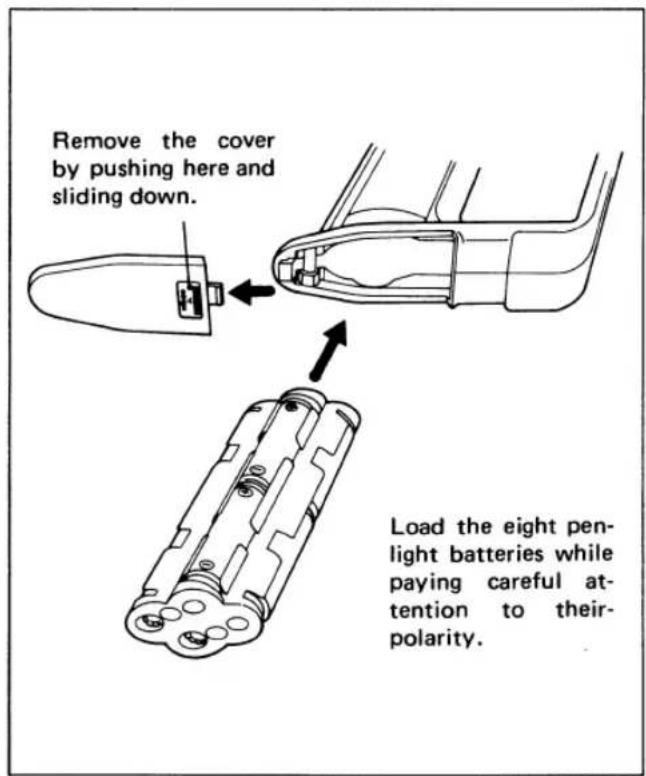
- Remove the battery cover at the bottom and insert eight penlight batteries in the correct polarity.
text_image
Remove the cover by pushing here and sliding down. Load the eight pen- light batteries while paying careful at- tention to their- polarity.- Battery cover
When loading or changing the eight penlight batteries, remove this cover as shown in the figure.
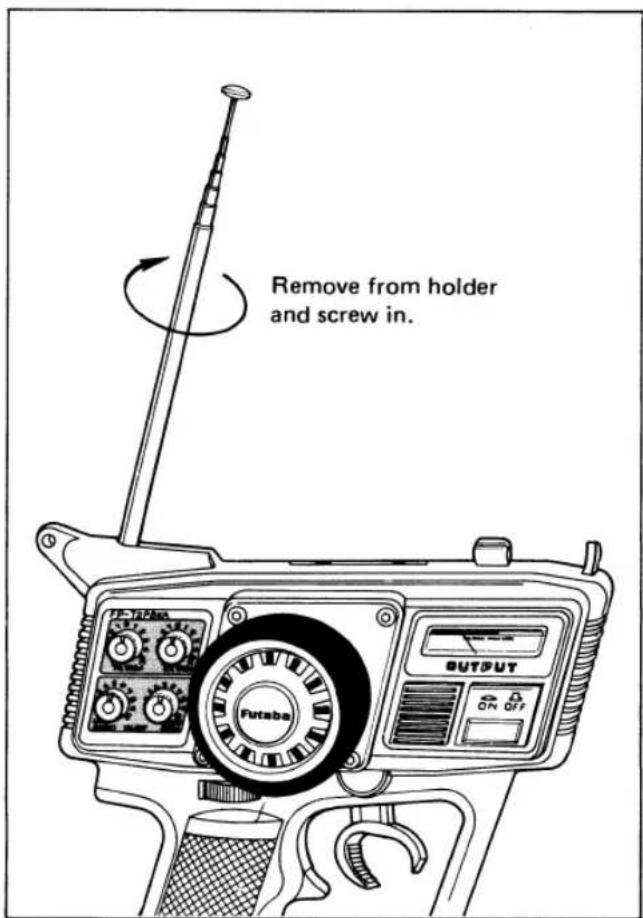
- The antenna
The antenna is 95 cm long. Install it as shown in the figure.
text_image
Remove from holder and screw in. PUTABA OUTPUT ON OFF• Transmitter crystal
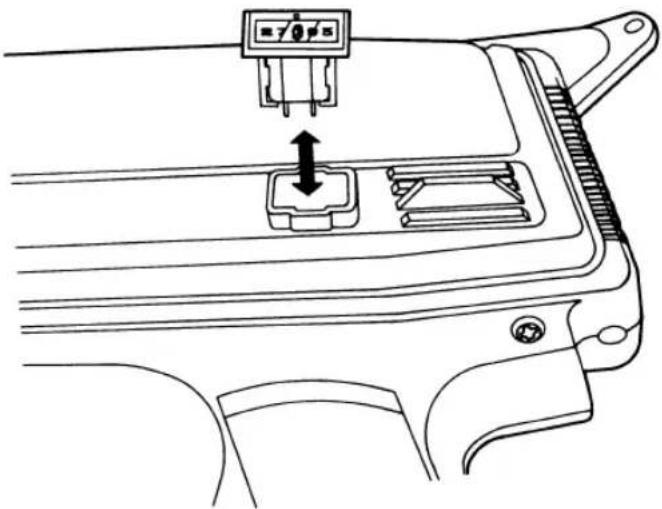
When changing the frequency, change the crystal. Use the AM crystal (transmitter and receiver pair) sold by Futabe. The transmitter crystal is marked TX and the receiver crystal is marked RX.
You can not change from one band to another (27 MHz to 75 MHz) simply by chansing crystals.
natural_image
Line drawing of a car interior showing a connector with an arrow pointing to a component (no text or symbols present)- Level meter
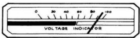
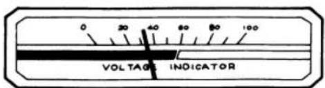
When the power switch is turned on, the meter pointer should move to the silver zone. If the pointer approaches the boundary between the silver and red zones, the battery voltage is low and the signal range will become shorter. When the meter pointer stops at the boundary between the silver and red zones, change the batteries.
- Extend the antenna fully and set the power switch to ON.
The level meter pointer should deflect to the silver zone. If the pointer does not move, or moves very little, check for poor battery contact, incorrect battery polarity, or faulty batteries.
text_image
0 30 40 60 80 100 VOLTAGE INDICATOR- If the pointer of the level meter deflects to the red zone, the range of the radio waves will become short. When the pointer drops to the boundary between the silver and red zones, change the batteries.
text_image
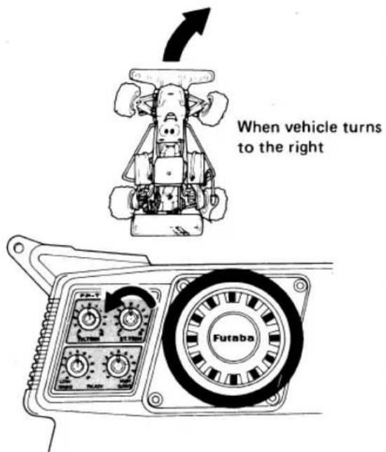
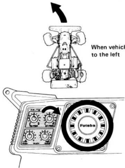
0 30 40 80 80 100 VOLTAGE INDICATOR- The trim knobs are used to fine adjust the steering angle. They are used to adjust the neutral position and for correcting the running posture after the mechanism is mounted. After test running, make corrections with the rod adjuster, etc. and operate the set with the trim knobs in the neutral position as much as possible.
▲ Steering Trim Knob Adjustment
In order to make vehicle run straight
text_image
When vehicle turns to the right FutabaMove the trim knob slowly to the left so that the vehicle runs straight.
In order to make vehicle run straight
text_image
When vehicle to the left FutabaMove the trim knob slowly to the right so that the vehicle runs straight.
*Adjust the trim knob so that the vehicle runs straight on a smooth road.
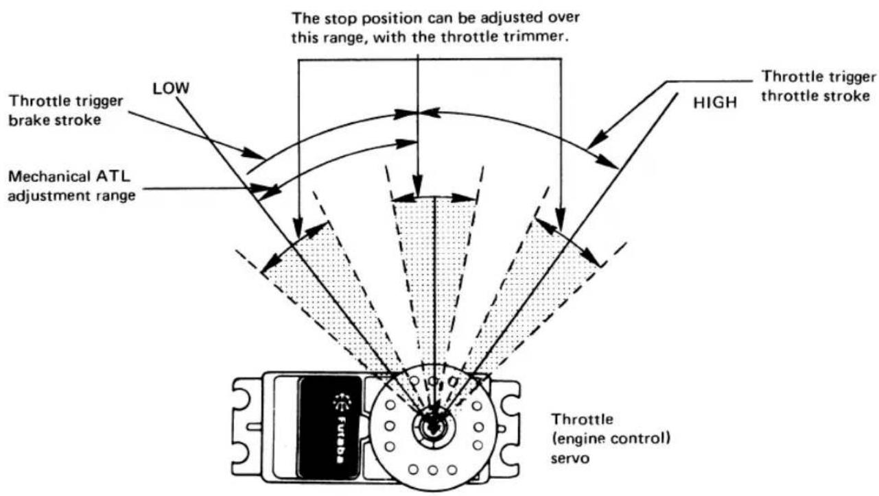
The throttle trim knob is used to fine adjust the speed controller stop position, etc.
text_image
The stop position can be adjusted over this range, with the throttle trimmer. THrottle trigger brake stroke LOW Mechanical ATL adjustment range HIGH Throttle trigger throttle stroke Throttle (engine control) servoThe throttle servo deflection can be adjusted at the transmitter as shown in the figure.
RECEIVER FP-R112JE AND SERVO FP-S148/S9601/S132H
text_image
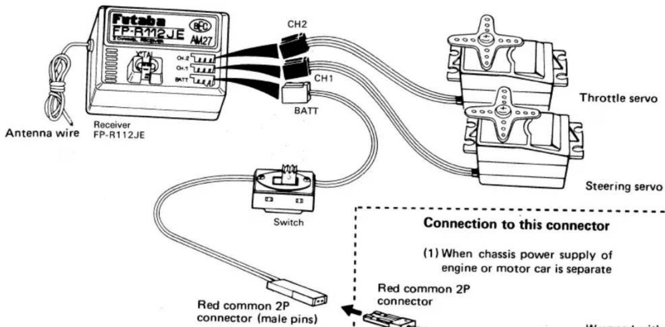
Futaba FP-R112JE AM27 CH2 CH1 BATT Antenna wire Receiver FP-R112JE Switch Red common 2P connector (male pins) Ch3 CH1 BATT Throttle servo Steering servo Connection to this connector (1) When chassis power supply of engine or motor car is separate Red common 2P connector Wrapped withConnect the servo and switch as shown in the figure and extend the transmitter and receiver antenna fully.
Connection to this connector
(1) When chassis power supply of engine or motor car is separate
Red common 2P connector
text_image
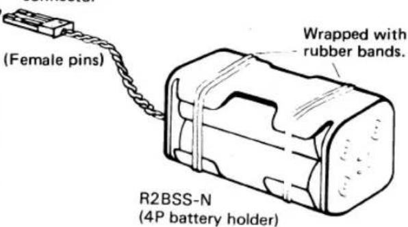
(Female pins) Wrapped with rubber bands. R2BSS-N (4P battery holder)(3) When motor car uses an ordinary common power supply
Rec common 2P connector

text_image
(Female pins)Buy the red common 2P connector from the kit manufacturer and connect to the controller.
Pin 1: Minus
Pin 2: Plus
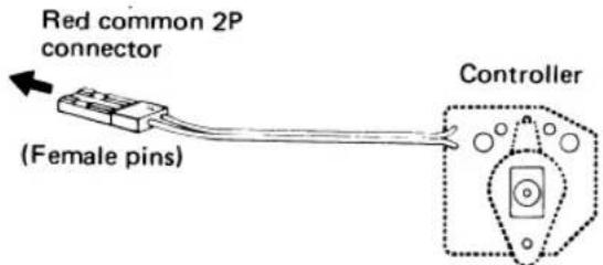
(2) When motor car uses a special BEC system (common power supply specifications)
text_image
Red common 2P connector (Female pins) ControllerConnect to the red common 2P connector of the controller.
The Futabe BEC system can also use a common power supply with the conventional four penlight batteries system (separate power supply).
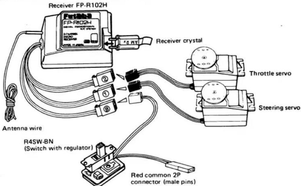
RECEIVER FP-R102H AND SERVO FP-S132H
text_image
Receiver FP-R102H FP-R102H SIGNAL PROFESSIONAL K/C PRESS 2 CHANNEL MOSO RECOR R4SW-BN Antenna wire R4SW-BN (Switch with regulator) Receiver crystal Throttle servo Steering servo Red common 2P connector (male pins)Connect the servo and switch as shown in the figure and extend the transmitter and receiver antenna fully.
●A common power supply regulator and diode may also be supplied with the speed controller, depending on the vehicle kit. Since they cause a voltage drop, always remove them.
- Set the transmitter power switch to ON, then set the receiver power switch to ON. The servos stop near the neutral position. Operate the transmitter wheel/trigger and check if each servo faithfully follows operation of the wheel/ trigger.

natural_image
Cartoon illustration of a person using a handheld device with a large eye symbol (no text or symbols present)From transmitter when switch turned on
natural_image
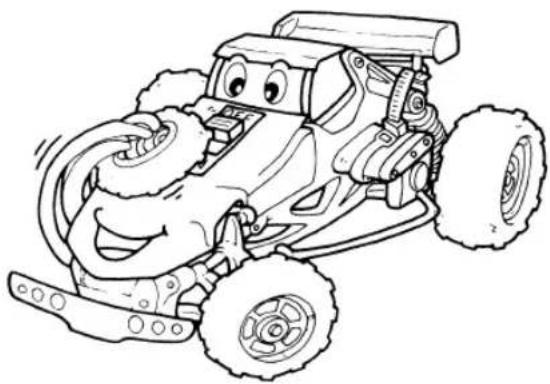
Cartoon illustration of a smiling off-road vehicle with wheels and motion blur (no text or symbols)From receiver when switch turned off
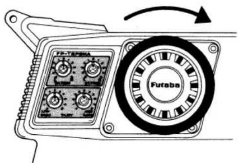
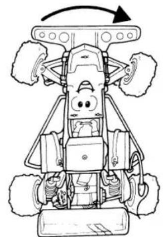
- Connect the pushrod to each servo horn, then check if the direction of travel of each servo matches the transmitter operation.
text_image
FP-TEPINA FutabaWhen the transmitter steering wheel was turned to the right
natural_image
Top-down line drawing of a cartoon-style off-road vehicle with wheels and a smiling face (no text or symbols)Vehicle also steers to the right
▲ FOR ELECTRIC MOTOR CAR
text_image
Operation of the throttle (engine control) servo can be set as shown in this figure. Adjustable by throttle trimmer Throttle stroke of throttle trigger Brake stroke of throttle trigger Adjustable within this range by throttle ATV high. (T2PBKA) Adjustable within this range by throttle ATV low. (T2PBKA) Throttle (engine control) servo- Operate each servo over its full travel and check if the pushrod binds or is too loose. Applying unreasonable force to the servo horn will adversely affect the servo and quickly drain the battery. Be especially careful when using 8.4 V.
● Always make the full stroke (including trim) of the servo horns somewhat larger than the full travel. Adjust the servo horns so that they move smoothly even when the trim knobs and wheel/trigger are operated simultaneously in the same direction. - Be alert for noise.
Always solder a noise killing capacitor to the running motor. If metal parts touch each other due to vibration, noise will be generated and cause the receiver servos to operate erroneously. We recommend the use of noiseless parts.
text_image
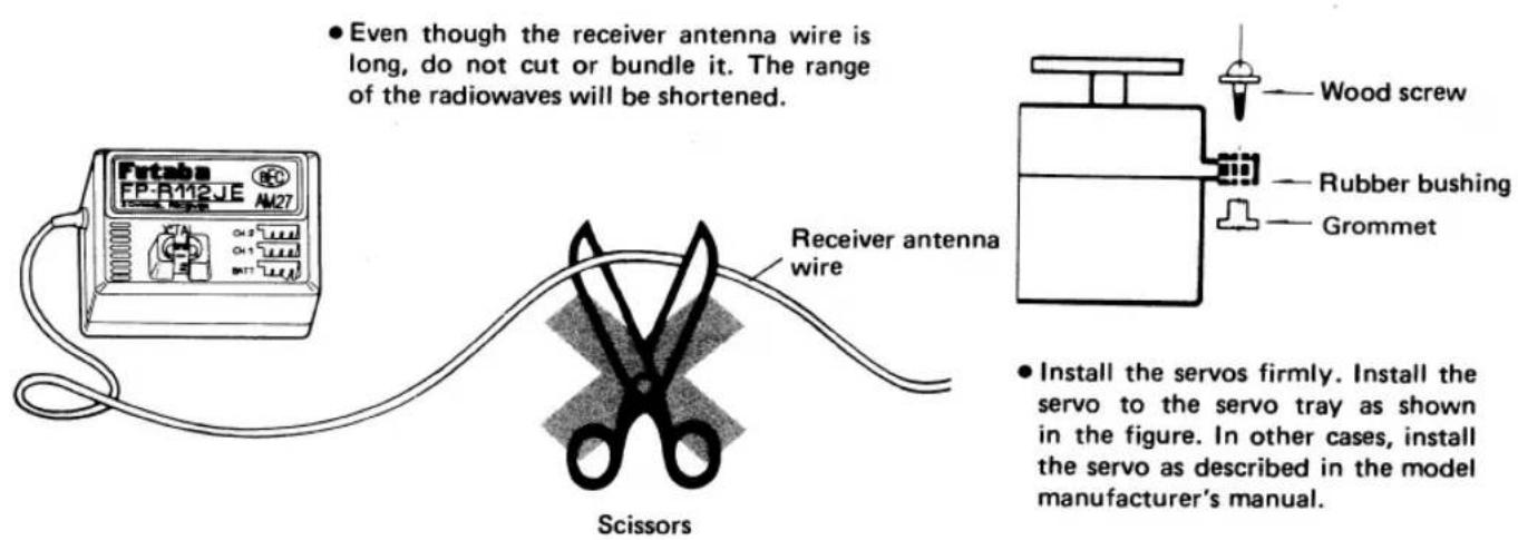
• Even though the receiver antenna wire is long, do not cut or bundle it. The range of the radiowaves will be shortened. Receiver antenna wire Scissors • Install the servos firmly. Install the servo to the servo tray as shown in the figure. In other cases, install the servo as described in the model manufacturer's manual.- A spare horn in provided. Use it as required.
- Wrap the receiver in sponge rubber and wrap rubber bands around the sponge rubber. Mount the receiver so it is not exposed to vibration, does not touch the frame, and does not move.
- When the receiver is installed on a board or used where it may be splashed with mud and water, place it in a plastic bag, etc. and wrap a rubber band around the open end of the bag to waterproof and dustproof the receiver. After use, remove the receiver from the bag to prevent condensation. Please remember that melted snow turns to water.
- Use the rubber bands wrapped around the receiver to hold the servo and switch leads.
- After mounting is complete, recheck each part, then check the transmitting range by making the transmitter antenna as short as possible and extending the receiver antenna fully and operating the set from a distance of 20 m to 30 m. The movement of each servo should follow the movement of the transmitter wheel/trigger.
- The crystal can be changed from the outside of the receiver case. Always use a Futaba transmitter and receiver crystal pair as the replacement crystals.
▲Digital Proportional Frequencies (FOR U.S.A.)
- The frequency of Futaba digital proportional sets can be changed within their own band. There are 2 different bands for you to choose from (27 MHz and 72-75 MHz.) Please see chart listed below for specific frequency and its intended use. Please note there are specific frequencies allocated for aircraft only and surface only use.
- The frequency can be changed within the same BAND by using a precisely matched pair of Futaba crystals. However, Futaba recommends that you return your system to our factory service department for frequency changing, as tuning may be necessary for proper operation, Changing frequency from one band to another is NOT possible.
● Always change frequency flag when frequency is changed. The frequency flag is to be attached to the top of antenna and the channel designation to the base. (See Drawing) - It is illegal to change crystals on 72-75 MHz bands in the U.S.A. unless performed by a licensed technician.
▲Antena Frequency Flag
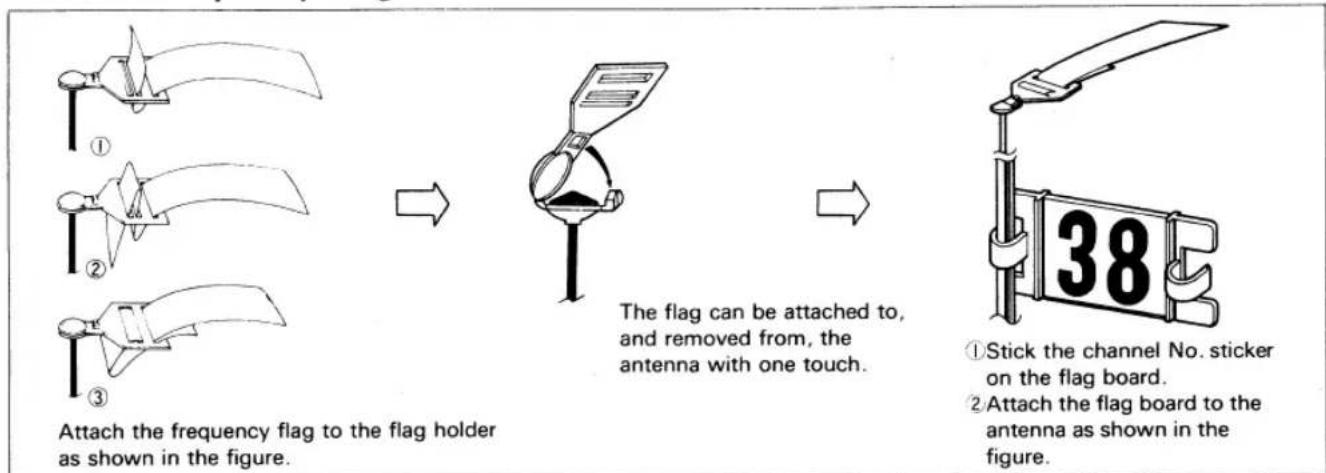
flowchart
graph LR
    A["①"] --> B["②"]
    B --> C["③"]
    C --> D["Attach the frequency flag to the flag holder as shown in the figure."]
    D --> E["The flag can be attached to, and removed from, the antenna with one touch."]
    E --> F["The flag can be attached to, and removed from, the antenna with one touch."]
    F --> G["Attach the flag board to the antenna as shown in the figure."]
    G --> H["①Stick the channel No. sticker on the flag board.<br>②Attach the flag board to the antenna as shown in the figure."]
▲ Frequency, Channel No., Flag Color (FOR U.S.A.)
| 26-27MHz-Aircraft/car/boat | 72MHz-Aircraft only | ||||||
| Color | |||||||
| 26.995 | Brown | *72.010 | 11 | *72.410 | 31 | *72.810 | 51 |
| 27.045 | Red | 72.030 | 12 | 72.430 | 32 | 72.830 | 52 |
| 27.095 | Orange | *72.050 | 13 | *72.450 | 33 | *72.850 | 53 |
| 27.145 | Yellow | 72.070 | 14 | 72.470 | 34 | 72.870 | 54 |
| 27.195 | Green | *72.090 | 15 | *72.490 | 35 | *72.890 | 55 |
| 27.255 | Blue | 72.110 | 16 | *72.510 | 36 | 72.910 | 56 |
| *72.130 | 17 | *72.530 | 37 | *72.930 | 57 | ||
| 50/53MHz-Aircraft/car/boat-Fcc Amature | 72.150 | 18 | 72.550 | 38 | *72.950 | 58 | |
| Licence required (2 and 3 channels not produced on these frequencies.) | *72.170 | 19 | *72.570 | 39 | *72.970 | 59 | |
| 72.190 | 20 | 72.590 | 40 | *72.990 | 60 | ||
| Channel No. | *72.210 | 21 | *72.610 | 41 | |||
| 50.800 | RC00 | 72.230 | 22 | 72.630 | 42 | ||
| *50.820 | RC01 | *72.250 | 23 | *72.650 | 43 | ||
| 50.840 | RC02 | 72.270 | 24 | 72.670 | 44 | ||
| *50.860 | RC03 | *72.290 | 25 | *72.690 | 45 | ||
| 50.880 | RC04 | 72.310 | 26 | 72.710 | 46 | ||
| *50.900 | RC05 | *72.330 | 27 | *72.730 | 47 | ||
| 50.920 | RC06 | 72.350 | 28 | 72.750 | 48 | ||
| *50.940 | RC07 | *72.370 | 29 | *72.770 | 49 | ||
| 50.960 | RC08 | 72.390 | 30 | 72.790 | 50 | ||
| *50.980 | RC09 | ||||||
| 75MHz-Car/boat only | |||||||
| Color | |||||||
| 53.100 | Black-Brown | *75.410 | 61 | *75.610 | 71 | *75.810 | 81 |
| 53.200 | Black-Red | 75.430 | 62 | 75.630 | 72 | 75.830 | 82 |
| 53.300 | Black-Orange | *75.450 | 63 | *75.650 | 73 | *75.850 | 83 |
| 53.400 | Black-Yellow | 75.470 | 64 | 75.670 | 74 | 75.870 | 84 |
| 53.500 | Black-Green | *75.490 | 65 | *75.690 | 75 | *75.890 | 85 |
| 53.600 | Black-Blue | 75.510 | 66 | 75.710 | 76 | 75.910 | 86 |
| 53.700 | Black-Violet | *75.530 | 67 | *75.730 | 77 | *75.930 | 87 |
| 53.800 | Black-Gray | 75.550 | 68 | 75.750 | 78 | 75.950 | 88 |
| *75.570 | 69 | *75.770 | 79 | *75.970 | 89 | ||
| *Effective JAN 1.1991 | 75.590 | 70 | 75.790 | 80 | 75.990 | 90 | |
CONVERSION TO NICAD SYSTEM FP-2PBKA ONLY (OPTIONAL)
To use a nicad battery with this set, modify the set with the optional FBPK-18 (2PBKA nicad battery conversion set).
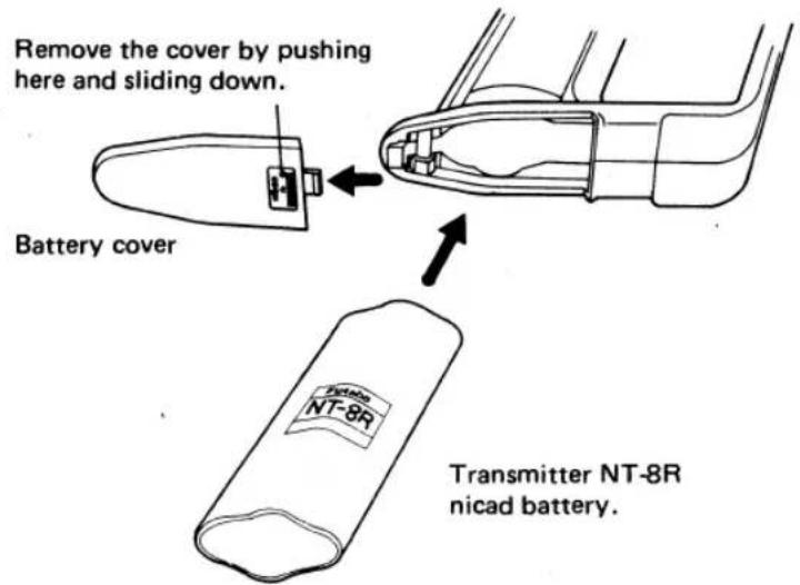
(1) Remove the battery cover as shown in this figure. Then install the transmitter NT-8R nicad battery and install the battery cover.
text_image
Remove the cover by pushing here and sliding down. Battery cover Transmitter NT-8R nicad battery.(2) Charging and how to use
(a) Connect the power plug of the FBC-8B (4) battery charger to the transmitter charging connector. Connect the 3PC red male connector to the receiver and servo NR-4QB nicad battery. Plug the battery charger into a 120 VAC outlet as shown in this figure.
(b) Normally recharge the battery for about 15 hours. If the battery has not been used for some time or is new, discharge and recharge it 2 or 3 times before use.
(c) If the battery is left discharged for a long time, its capacity will decrease and the life of the battery will be shortened. After use, recharge the battery before storing it.
(d) Always recharge the battery before use.
(e) A fully charged battery can be used for about two hours at 10 minutes/running.

text_image
Battery charger Type FBC-8B (4) NR-4QB Charging connectorLIMITED WARRANTY
Your new FUTABA Digital Proportional R/C System is warranted to the original purchaser for one full year from the date of purchase against defects in material and workmanship. During this period Futaba will repair or replace, at our discretion, the defective component. This warranty does not apply to any unit which has been improperly installed, handled, abused, damaged in a crash, nor to any unit which has been repaired or altered by unauthorized agencies. Under no circumstances will the buyer be entitled to consequential or incidental damages. This Limited Warranty gives you specific legal rights; you may also have other rights which vary from state to state. Batteries and plastic housings are not covered by warranty.
REPAIR SERVICE
- When requesting repair of trouble that has occurred suddenly from long use, describe the trouble symptoms in as much detail as possible. This will facilitate detection of the trouble point and shorten the repair period greatly.
- Defects caused by faulty materials or workmanship will be corrected free of charge. Refer to warranty statement for details.
FP-S148
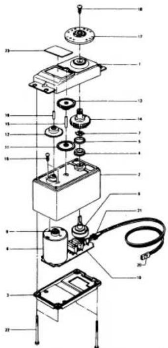
text_image
Exploded view diagram of an electrical device with numbered components and labeled parts| No. | Part name | Pars No. | No. | Part name | Part No. |
| 1. | upper case | FCS-48 | 13. | 3rd gear | FGS-48 |
| 2. | Middle case | FCS-48 | 14. | Final gear | FGS-48 |
| 3. | Bottom case | FCS-48 | 15. | Intermediate shaft | S02495 |
| 4. | Metal bearing | S04137 | 16. | 2nd shaft | S02494 |
| 5. | Metal bearing | S04136 | 77 | Servo horn D | FSH-6W |
| 6. | Potentiometer | I39668 | 18. | Binding head tapping screw 2.6x8 | FSH-41 |
| 7. | Potentiometer drive plate | S02753 | 19. | Printed wiring board S148 | AS1157 |
| 8. | Motor | S91239 | 20. | S148 3PB-WRB300G | AT2453 |
| 9. | Motor pinion | S02461 | 21. | w gum bush | S90045 |
| 10. | Screw | J50002 | 22. | pan head truss screw | S50360 |
| 11. | 1st gear | FGS-48 | 23. | Nameplate S148 | S60099 |
| 12. | 2nd gear | FGS-48 | |||
FP-S9601
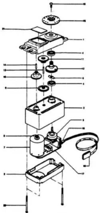
text_image
Exploded view diagram of a mechanical assembly with labeled components in Chinese| No. | Part name | Part No. | No. | Part name | Part No. |
| 1. | Upper case | FCS-35 | 12. | Final gear | FGS-9601 |
| 2. | Middle case | FCS-35 | 13. | Intermediate shaft | S04285 |
| 3. | Bottom case | FCS-35 | 14. | 2nd shaft | S02767 |
| 4. | Ball bearing | S04130 | 15. | Servo horn D | FSH-6W |
| 5. | Potentiometer | I39995 | 16. | Horn mounting screw | FSH-41 |
| 6. | VR drive plate | S05626 | 17. | Printed wiring board | AS1317 |
| 7. | Coreless motor | S91260 | 18. | 3PB-WRB-170 | AL0705 |
| 8. | Motor pinion | S05532 | 19. | Lead wire packing | S90045 |
| 9. | 1st gear | FGS-9601 | 20. | Case mounting screw | J40070 |
| 10. | 2nd gear | FGS-9601 | 21. | Nameplate | S60193 |
| 11. | 3rd gear | FGS-9601 | |||
FP-S132H
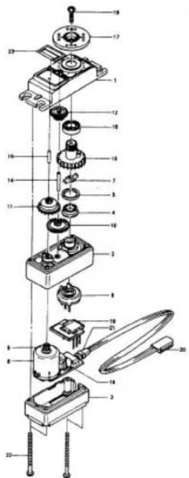
text_image
Exploded view diagram of a mechanical assembly with numbered parts for identification| No. | Part name | Part No. | No. | Part name | Part No. |
| 1. | Upper case | S05820 | 14. | Intermediate shaft | S02480 |
| 2. | Middle case | S05842 | 15. | 2nd shaft | S02481 |
| 3. | Bottom case | S05843 | 16. | Ball bearing | S04130 |
| 4. | Metal bearing | S04137 | 17. | Servo horn D | S01239 |
| 5. | Metal bearing | S04136 | 18. | Horn mounting screw | J55178 |
| 6. | Potentiometer | I 39668 | 19. | S132HA Printed wiring board | AMS110048 |
| 7. | VR drive plate | S05626 | 20. | S132H 3PB-WRB-300 | AT2238 |
| 8. | Motor | S91249 | 21. | Lead wire packing | S90045 |
| 9. | Motor pinion | S02788 | 22. | Case mounting screw | J50083 |
| 10. | 1st gear | S02787 | 23. | S132H Name-plate | S60128 |
| 11. | 2nd gear | S03250 | |||
| 12. | 3rd gear | S03252 | |||
| 13. | Final gear | S03254 | |||
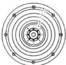
▲ SPLINED HORNS
This horn permits shifting of the servo neutral position at the servo horn. Setting and shifting the neutral position.
a) Angle divisions
1) The splined horn has 25 segments. The amount of change per segment is; 360 ÷ 25 = 14.4^
2) The minimum adjustable angle is determined by the number of arms or number of the holes. For four arms, the minimum adjustable angle is:
$$ 3 6 0 ^ {\circ} \div \frac {(2 5 \times 4)}{\text { Number of divisions }} = 3. 6 ^ {\circ} $$
b) Effect
To shift the holes center line to the right (clockwise) relative to baseline A, shift arm 2 to the position of arm 1 and set it to the position closet to baseline A.
[Example] For a four arm horn, the angular shift per segment is 14.4^ . The shift to the right is 90^ - (14.4 × 6) = 3.6^
To shift by the same angle in the opposite direction, use the opposite arm number.
For a six arm horn, turn the arm counterclockwise and set arm 2 to the position of arm 1. The adjustable angle is 60^ - (14.4 × 4) = 2.4^ .
Arm 3 shift 4.8^ to the right, arm 6 shifts 2.4^ to the left, and arm 4 shifts 7.2^ to the right and left.
▲ WHEN VEHICLE WILL NOT BE USED
Be sure and release the connector of running Nicd battery except when you are on the way to the starting line.
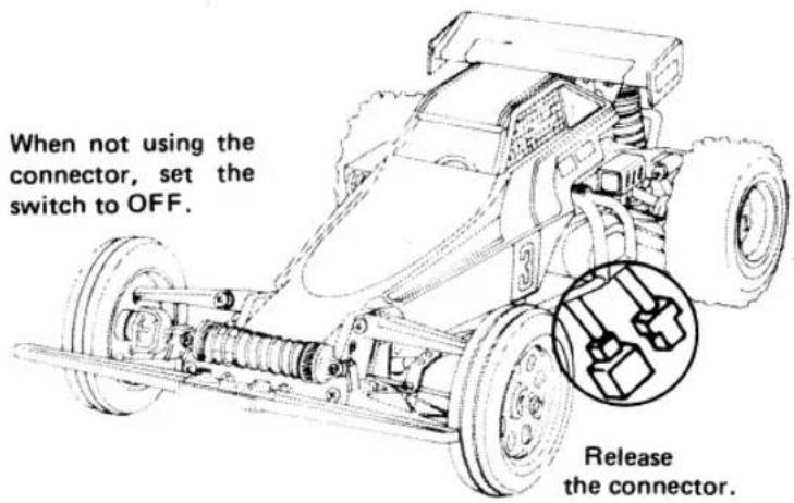
text_image
When not using the connector, set the switch to OFF. Release the connector.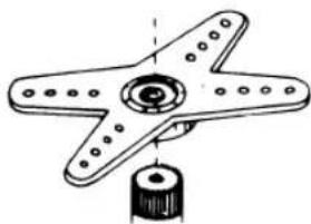
natural_image
Technical line drawing of a star-shaped mechanical component with a central hub and a cylindrical base (no text or symbols)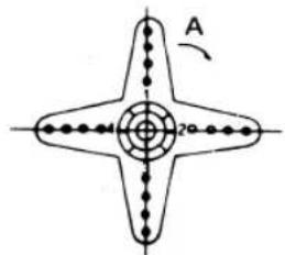
text_image
A 20°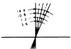
text_image
14 4 10 8 1 2 3 6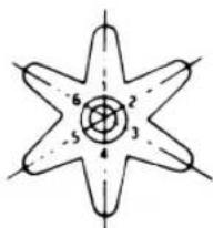
text_image
6 2 5 3The following splined horns are optional.
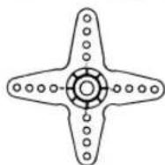
HORN A
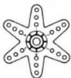
HORN B
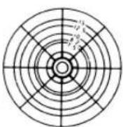
HORN C
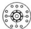
HORN D
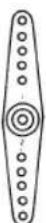
HORN E
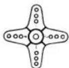
HORN F
natural_image
Concentric circular diagram with evenly spaced nodes and radial lines, no text or symbols presentHORN G
IMPORTANT : Receiver Antenna Routing
To obtain the best possible range (car to transmitter distance) and reduce the possibility of interference, please observe these antenna routing instructions.
Failure to follow these guidelines can result in loss of control or limited range.
1) NEVER cut your receiver's antenna wire. Your system has been precisely tuned to the full length of the stock antenna.
2) Excess antenna wire should NOT be tightly coiled. To safely store the excess wire make an antenna shortener from a small piece of stiff cardboard. This will provide maximum reception and prevent tangling and breakage of the wire.
3) When routing the antenna wire to the antenna tube keep the wire away from battery and speed control wiring. The high power of the NiCd battery creates electrical "noise" which can cause interference.
SNOW IS WATER
Remember that operating your FX10 on snow or in wet areas is not recommended. Melted snow becomes water which will damage or short out your system's electronics.
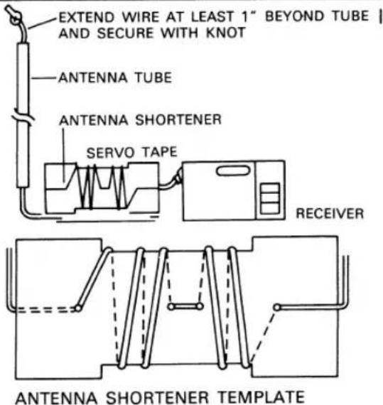
text_image
EXTEND WIRE AT LEAST 1" BEYOND TUBE | AND SECURE WITH KNOT ANTENNA TUBE ANTENNA SHORTENER SERVO TAPE RECEIVER ANTENNA SHORTENER TEMPLATE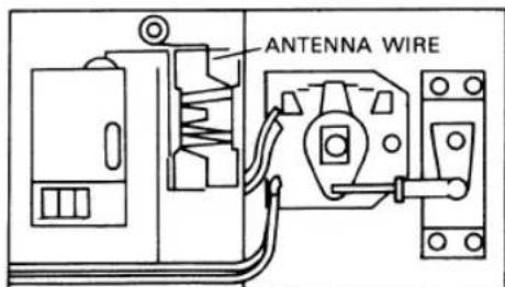
text_image
ANTENNA WIREKEEP ANTENNA WIRE AWAY FROM POWER WIRES

FUTABA CORPORATION OF AMERICA
4 Studebaker, Irvine California 92718, U.S.A.
Phone:714-455-9888 Telex:23-0691227 Facsimile:714-455-9899
FUTABA CORPORATION
Tokyo Office: INAGAKI BLDG., 3F 1-21-3, Kanda sudacho, Chiyoda-ku, Tokyo, Japan.
Phone:(03)3255-6811 Facsimile:(03)3255-6880