CC-132 - Rückfahrkamera TREBS - Kostenlose Bedienungsanleitung
Finden Sie kostenlos die Bedienungsanleitung des Geräts CC-132 TREBS als PDF.


Benutzerfragen zu CC-132 TREBS
0 Frage zu diesem Gerät. Beantworten Sie die, die Sie kennen, oder stellen Sie Ihre eigene.
Eine neue Frage zu diesem Gerät stellen
Laden Sie die Anleitung für Ihr Rückfahrkamera kostenlos im PDF-Format! Finden Sie Ihr Handbuch CC-132 - TREBS und nehmen Sie Ihr elektronisches Gerät wieder in die Hand. Auf dieser Seite sind alle Dokumente veröffentlicht, die für die Verwendung Ihres Geräts notwendig sind. CC-132 von der Marke TREBS.
BEDIENUNGSANLEITUNG CC-132 TREBS
User manual
2.4GHz Wireless Rearview Parking System with Color LCD Monitor
Model No.: CC-132
natural_image
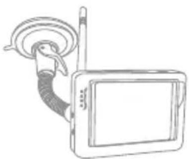
Line drawing of a portable electronic device with antenna and cable (no text or symbols)OLA-132

CONTENTS
Foreword 1
Packing List 1
Structure 2
Installation 3
Specifications 8
FCC Information Back cover
*Trebs is not responsible for any damage resulting from installation and use of this product.
*2.4 GHz devices as e.g. cell phones, navigation, bluetooth and Wi-Fi system scan have influence on the performance of this product.
FOREWORD
CONGRATULATIONS. The CC-132 is a camera car rearview system with 3.6" TFT-LCD monitor. The Rearview Camera, when used as described, will give you years of dependable service in your car, truck, RV, or mini-van. We have taken numerous measures in quality control to ensure that your product arrives in top condition, and will perform to your satisfaction.
PACKING LIST
①
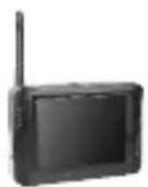
②
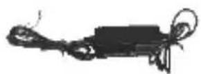
③
④

⑤
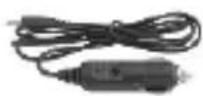
⑥
⑦
⑧
⑨
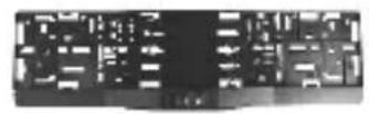
① Rearview Camera
② Monitor
③ Wireless Transmission Box
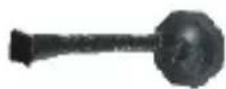
⑦ Suction Holder
⑨ Cable Ties
④ Sheet Metal Screws
⑤ In-Line Wire Connectors
⑥ Power Adapter
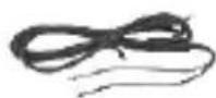
⑧ Monitor Wiring Harness
STRUCTURE
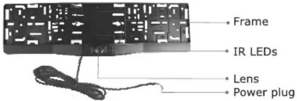
Rearview Camera
text_image
Frame IR LEDs Lens Power plugWireless Transmission Box

text_image
Power Wire Wireless Transmission Box Connect Wire Rearview CameraTFT-LCD Monitor
text_image
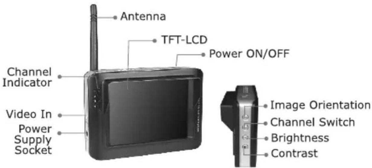
Antenna TFT-LCD Power ON/OFF Channel Indicator Video In Power Supply Socket Image Orientation Channel Switch Brightness ContrastINSTALLATION
Installation of the camera:
- Loosen the license plate bolt or screw, and then remove the license plate on the rear of your car.
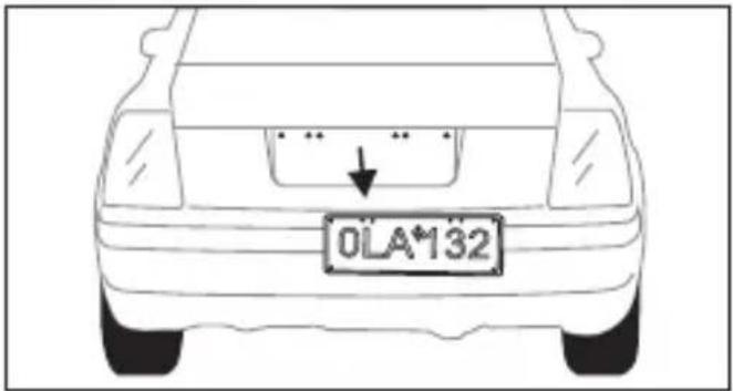
text_image
OLA*132- Drill one hole for power cable in the middle of below license plate, where the camera will exist.
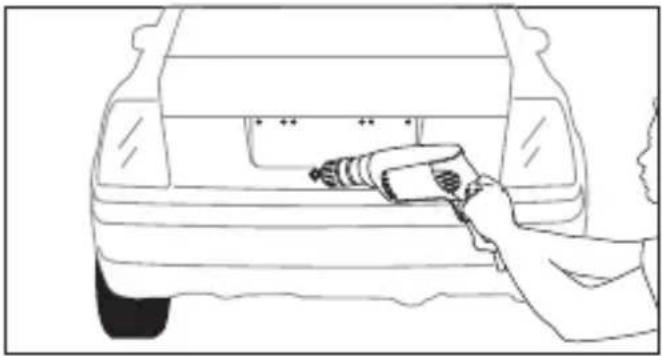
natural_image
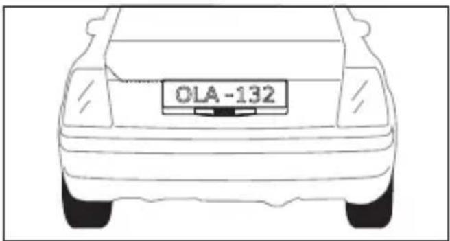
Line drawing of a car back view with a hand holding a handheld tool (no text or symbols)- Install the frame camera with bolt/screw, and adjust the camera to a suitable angle. Tow the power wire into the car through the interstices of the car.
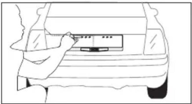
natural_image
Line drawing of a car front view showing the dashboard and seat area (no text or symbols)- Install the license plate to the frame.
natural_image
Front view of a car with a license plate (OLA-132) on the back, no text or symbols on the bodyWireless Transmission Box Installation
1. Wiring Connector Diagram
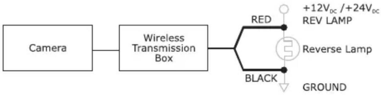
flowchart
graph LR
    A["Camera"] --> B["Wireless Transmission Box"]
    B --> C["Red"]
    C --> D["+12V_DC / +24V_DC REV LAMP"]
    B --> E["Reverse Lamp"]
    B --> F["BLACK"]
    F --> G["GROUND"]
2. Basic Installation
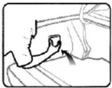
1). Find proper spaces for install the transmission box.
natural_image
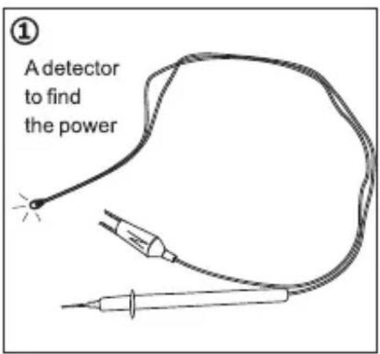
Line drawing of a hand holding a small object, possibly a tool or device, with no visible text or symbols.2). A detector to find the power: how to find the power from the reverse light?
Introductions: black clamp connects to the ground wire. Use the red pen to find the power from the reverse light until the LED light is on. Then connect our red power line to the power from the reverse light, and the black to the ground wire.
text_image
① A detector to find the power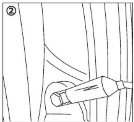
natural_image
Line drawing of a car interior with a handheld device, no text or symbols present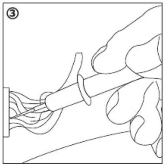
natural_image
Line drawing of a hand pouring liquid into a container with a syringe (no text or symbols)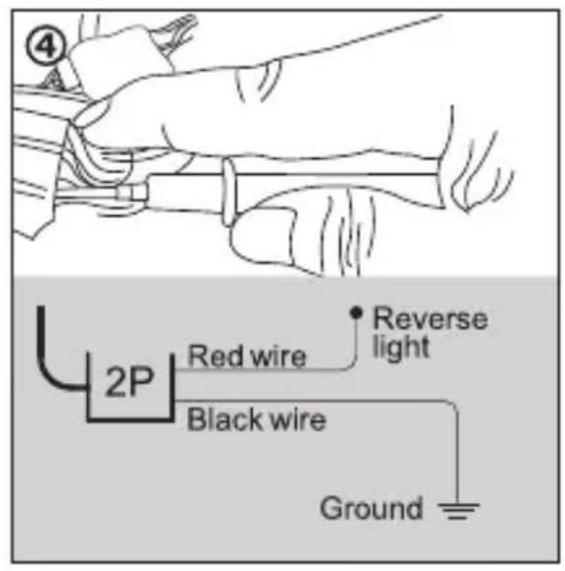
text_image
4 2P Red wire Reverse light Black wire Ground3. In-Line Wire Connector Instructions
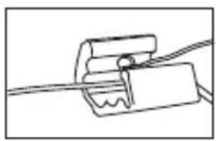
You do not need to use the In-Line Wire Connectors. The Transmission Box can be wired directly to the reverse light circuit by stripping the reverse light wires then twisting Transmission Box wires to the exposed reverse light wires. Once connected, wrap with electrical tape. DO NOT attempt this if you are not knowledgeable with electrical installation practices.

natural_image
Pure mechanical assembly diagram showing a clamping mechanism with no text or symbolsInsert the existing wire to be tapped.
natural_image
Simple line drawing of a mechanical clamp or bracket with a wire, no text or symbols presentInsert the wire to be attached.
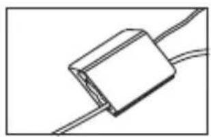
natural_image
Simple line drawing of a rectangular object with two wires extending from it (no text or symbols)Crimp tap then close lock
Installation of the monitor:
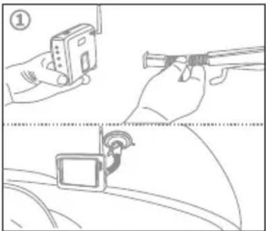
- Use the suction holder to install the monitor. The suction holder is stamped on the front window glass.
- Connect power of the monitor. There are two methods as below:
A: According to the same steps, find power from the car power circuit in front, and connect the cables correctly.
B: Use the cigarette lighter adapter included in the package to get the power.
text_image
Diagram illustrating car safety instructions with labeled steps and hand positions for monitoring and tracking.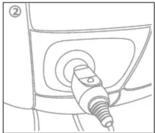
natural_image
Line drawing of a car charging plug (no text or symbols)Test The System
- Engage the parking brake and turn the ignition key to the ON position.
DO NOT start the vehicle. Put the gear shift into reverse.
-
The camera will start sending signal, and the monitor will detect the signal and turn itself ON. If the monitor does not come ON press the ON/OFF button.
-
If the image does not match your rear view mirror, press the top button on the monitor to change the image until it matches your rearview mirror.
-
When you take the gear shift out of reverse, the camera will automatically turn OFF, and the monitor will shut down.
Route all wire behind interior panels or under carpeting so they are hidden.
Use supplied cable ties to neatly gather any excess wire.
Keep camera lens and monitor clean to ensure optimum picture quality.
SPECIFICATIONS
| Items | CC-132 | |
| Camera + Wireless Transmission Box | Imaging Sensor | CMOS |
| Total Pixels | 720×480(NTSC); 720×576(PAL) | |
| Modulation Mode | FM | |
| Bandwidth | 18MHz | |
| Transmission Frequency | 2414,2432,2450,2468MHz | |
| Horizontal View Angle | 80 degree | |
| Transmission Power | 2mW/FCC,10wm/CE | |
| Minimum Illumination | 0 Lux (IR ON) | |
| IR Night Range | 4m | |
| Power Supply | Supplied By Transmission Box | |
| Consumption Current (Max.) | 120mA | |
| Dimensions (W x D x H) | 525×148×45(mm) | |
| Weight (about) | 264g | |
| Receiver | LCD Screen Type | 3.6" TFT-LCD |
| Effective Pixels | 320 × 240 | |
| Video System | NTSC/PAL | |
| Color Configuration | R.G.B.delta | |
| Received Sensitivity | ≤-85dBm | |
| Power Supply Voltage | +12/+24Vdc | |
| Consumption Current (Max.) | 250mA | |
| Unobstructed Effective Range(Min.) | 50m | |
| Dimensions(W x D x H) | 108 ×37×75(mm) | |
| Weight (About) | 165g | |
| Operating Temperature | -10°C~+50°C/+14°F~+122°F | |
| Operating Humidity (Max.) | 85%RH |
* Channel Frequency: CH1=2,414MHz; CH2=2,432MHz;
CH3=2,450MHz; CH4=2,468MHz, only CH4 is available.
* The actual transmission range may vary according to the weather, location, interference and building construction.
* All the specifications are subject to minor change without prior notice.
CAUTIONS
- The apparatus shall not be exposed to dripping or splashing and that no objects filled with liquids, such as vases, shall be placed on the apparatus.
- Turn off the camera/receiver if the system is not in use.
- The adapter is used as the disconnect device from the mains. The adapter shall remain readily operable.
- The camera/receiver can only be completely disconnected from the mains by unplug the adapter.
- Do not cut the DC power cable of the apparatus to fit with another power source.
- Attention should be drawn to the environment aspects of battery disposal.
The graphics included are subject to minor change without notice.
FCC INFORMATION
This device complies with part15 of the FCC Rules. Operation is subject to the following two conditions:
(1) this device may not cause harmful interference,
(2) this device must accept any interference received, including interference that may cause undesired operation.
Changes or modifications not expressly approved by the party responsible for compliance could void the user's authority to operate the equipment.
EU Environmental Protection
Waste electrical products should not be disposed of with household waste. Please recycle where facilities exist. Check with your Local Authority or retailer for recycling advice.