MCP401RC - Schalter Ei Electronics - Kostenlose Bedienungsanleitung
Finden Sie kostenlos die Bedienungsanleitung des Geräts MCP401RC Ei Electronics als PDF.


Benutzerfragen zu MCP401RC Ei Electronics
0 Frage zu diesem Gerät. Beantworten Sie die, die Sie kennen, oder stellen Sie Ihre eigene.
Eine neue Frage zu diesem Gerät stellen
Laden Sie die Anleitung für Ihr Schalter kostenlos im PDF-Format! Finden Sie Ihr Handbuch MCP401RC - Ei Electronics und nehmen Sie Ihr elektronisches Gerät wieder in die Hand. Auf dieser Seite sind alle Dokumente veröffentlicht, die für die Verwendung Ihres Geräts notwendig sind. MCP401RC von der Marke Ei Electronics.
BEDIENUNGSANLEITUNG MCP401RC Ei Electronics

Electronics®
MCP401RC Manual Call Point
PLEASE NOTE: The MCP401RC is designed for use with the following models of Smoke/Heat/CO Alarms - Ei161RC, 164RC, 166RC, 141, 144, 146, 151TL, 154TL, 156TLH, 261ENRC, 261DENRC.
When the black spot on the front face of the MCP401RC is pressed, an alarm signal will be sent along the interconnect line and all interconnected alarms will sound. The MCP401RC switch element can be reset using the plastic key supplied.
text_image
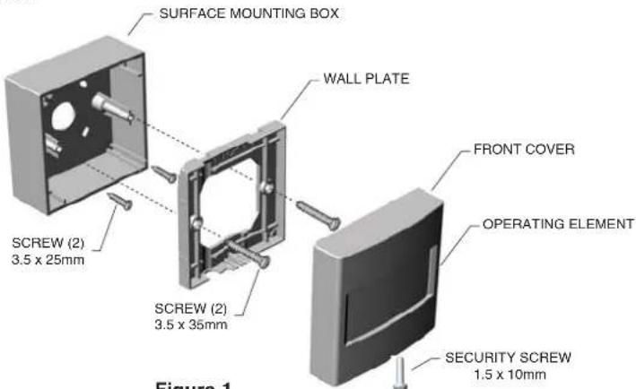
SURFACE MOUNTING BOX WALL PLATE FRONT COVER OPERATING ELEMENT SCREW (2) 3.5 x 25mm SCREW (2) 3.5 x 35mm SECURITY SCREW 1.5 x 10mm Figure 1Figure 1
Installation & Wiring
WARNING: This Manual Call Point should be installed by a qualified electrician in accordance with the Requirements for Electrical Installations published by the Institute of Electrical Engineers (BS7671 current edition). A maximum of 4 MCP401RC units can be installed on one system in addition to 12 interconnect alarms.
1 Disconnect the AC mains power supply from the circuit that is to be used to power the smoke/heat alarms and the MCP401RC.
2 Install the Smoke/Heat/CO Alarms as per the Installer Instructions supplied with the alarms.
3 Select a suitable location where the MCP401RC can be easily accessed. The unit should not be exposed to dripping or splashing.
4 Route the wiring (Live, Neutral, Interconnect/Control and Earth) to the MCP401RC siting location. A minimum 0.75mm² cable should be used.
5 With the 25mm screws provided, fix the mounting box to the wall.
6 Secure the wall plate to the mounting box using the 35mm machine screws provided.
text_image
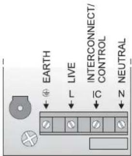
EARTH LIVE INTERCONNECT/ CONTROL NEUTRALFigure 2
text_image
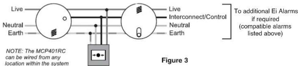
Live Neutral Earth Live Interconnect/Control Neutral Earth To additional Ei Alarms if required (compatible alarms listed above) NOTE: The MCP401RC can be wired from any location within the system Figure 37 Connect the wiring as shown in Figures 2 & 3 previously. Note: the Earth connection is for convenient termination of the earth conductor and is not required for the safety of the unit. The wiring should be installed securely (e.g. tie wrap together) to prevent a hazard if one becomes detached.
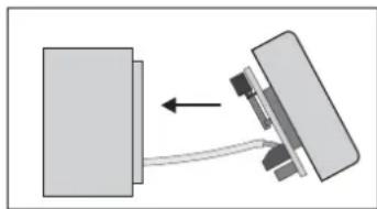
8 Carefully slide the front cover and circuit board diagonally into the mounting box, top section first (see Figure 4).
9 Then carefully locate the top of the front cover onto the top of the wall plate and hinge down to snap securely in place (see Figure 5).
natural_image
Diagram showing two mechanical components with arrows indicating motion or force direction (no text or symbols)Figure 4

natural_image
Diagram of a mechanical device with a rotating arrow indicating rotation (no text or symbols)Figure 5
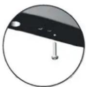
Figure 6
10 Fit the security screw to the call point - the hole for this is on the bottom face of the front cover (see Figure 6). This is essential for electrical safety as mains is present within the unit.
11 Reconnect the AC mains power to the circuit and check that the green mains indicator lights on the Smoke/Heat/CO Alarms are on.
Testing
It is recommended that the MCP401RC is tested directly after installation and then at least monthly.
1 Test that the MCP401RC call point triggers the alarm(s) by pressing the black spot on the front cover. A striped warning indicator should drop down into view on the front face (visible through the clear plastic window). Check that each alarm in the system is sounding.
2 Reset the MCP401RC by following the instructions in the Resetting section below. The alarms should stop sounding.
3 Now turn off the mains power to the system. Repeat the test above (this checks the rechargeable back-up in the unit). Reinstate the mains power to the system. The MCP401RC will operate in standby with mains off for over 6 months. With the Manual Call Point triggered it can give an alarm signal for over 16 hours.
Resetting
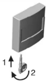
To reset the unit, insert the reset key into the hole in the bottom of the front cover. The striped warning indicator should disappear. With the key still inserted, twist it anticlockwise until the operating element clicks back into place, then remove the reset key (see Figure 7).
natural_image
3D diagram of a mechanical component with two directional arrows labeled 1 and 2, no text or symbols present.Figure 7
Opening Unit / Removal
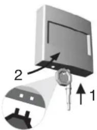
To detach the front cover, remove the security screw and insert the reset key into the bottom of the cover. With the key firmly inserted, hinge the bottom of the cover away from the wall plate/ mounting box (the reverse motion to fitting). See Figure 8.
text_image
Diagram showing a device with labeled parts and an arrow indicating direction, including numbered annotations 1 and 2.Figure 8
The crossed cut wheelle bin symbol that is on your product indicates that this product should not be disposed of via the normal household waste stream. Proper disposal will prevent possible harm to the environment or to human health. When disposing of this product please separate it from other waste streams to ensure that it can be recycled in an environmentally sound manner. For more details on collection and proper disposal, please contact your local government of ce or the retailer where you purchased this product.

© Ei Electronics 2007
P/N B16073 Rev 0
Aico Ltd. Mile End Business Park, Maesbury Rd, Oswestry, Shropshire, SY10 8NN, U.K. Tel: 0870 7584000 www.aico.co.uk
Ei Electronics. Shannon, Ireland. Tel: +353 (0)61 471277 www.eielectronics.com