MMD2-18HDI - Klimaanlage Maxicool - Kostenlose Bedienungsanleitung
Finden Sie kostenlos die Bedienungsanleitung des Geräts MMD2-18HDI Maxicool als PDF.


| Produkttyp | Split-Klimaanlage |
| Modell | MMD2-18HDI |
| Marke | Maxicool |
| Energieeffizienzklasse | A++ |
| Kühlleistung | 18000 BTU/h |
| Heizleistung | 18000 BTU/h |
| Spannungsversorgung | 230 V ~ 50 Hz |
| Kältemittel | R32 |
| Schalldruckpegel (Innengerät) | 42 dB(A) |
| Schalldruckpegel (Außengerät) | 55 dB(A) |
| Abmessungen (Innengerät) | 900 x 290 x 220 mm |
| Abmessungen (Außengerät) | 800 x 550 x 330 mm |
| Gewicht (Innengerät) | 12 kg |
| Gewicht (Außengerät) | 30 kg |
| Betriebstemperaturbereich | -15°C bis 43°C |
| Filter | Waschbarer Feinfilter |
| Fernbedienung | Ja, inklusive |
| Timer | 24-Stunden-Timer |
| Besondere Funktionen | Automatikbetrieb, Schlafmodus, Entfeuchtung |
| Wartung | Filter regelmäßig reinigen |
| Sicherheit | Kindersicherung, Überhitzungsschutz |
| Ersatzteile | Filter und Fernbedienung erhältlich |
| Reparaturfähigkeit | Modulares Design, einfacher Zugang zu Komponenten |
Häufig gestellte Fragen - MMD2-18HDI Maxicool
Benutzerfragen zu MMD2-18HDI Maxicool
0 Frage zu diesem Gerät. Beantworten Sie die, die Sie kennen, oder stellen Sie Ihre eigene.
Eine neue Frage zu diesem Gerät stellen
Laden Sie die Anleitung für Ihr Klimaanlage kostenlos im PDF-Format! Finden Sie Ihr Handbuch MMD2-18HDI - Maxicool und nehmen Sie Ihr elektronisches Gerät wieder in die Hand. Auf dieser Seite sind alle Dokumente veröffentlicht, die für die Verwendung Ihres Geräts notwendig sind. MMD2-18HDI von der Marke Maxicool.
BEDIENUNGSANLEITUNG MMD2-18HDI Maxicool
Before using your air conditioner, please read this manual carefully and keep it for future reference.
INVERTER ONE-TWO / ONE-THREE /ONE- FOUR/ONE-FIVE SPLIT-TYPE ROOM AIR CONDITIONER
INSTALLATION MANUAL
MaxiCool
MODEL: MMD2-18HDI MMD3-27HDI
- Please read this installation manual completely before installing the product.
- If the power cord is damaged, replacement work shall be performed by authorised personnel only.
- Installation work must be performed in accordance with the national wiring Standards by authorised personnel only.
- Contact an authorised service technician for repair, maintenance or installation of this unit.
SAFETY PRECAUTIONS
Warning 2
Caution 2
INSTALLATION INSTRUCTIONS
Selecting installation place....3
Wall-mounted type ....3
Accessories 4
Four-way cassette type 9
Duct & Ceiling type 12
Ceiling and Floor type 16
Floor and Standing type(Console)....19
Outdoor unit installation ....23
REFRIGERANT PIPE CONNECTION
Refrigerant pipe connection ....24
ELECTRICAL WORK
Electrical work 25
AIR PURGING
Air purging with vacuum pump 27
Safety and leakage check 29
TEST RUNNING
Test running 30
Read This Manual
Inside you will find many helpful hints on how to install and test the air conditioner properly.
All the illustrations and specifications in the manual are subject to change without prior notice for product improvement. The actual shape should prevail.

CAUTION
- Contact an authorised service technician for repair or maintenance of this unit.
- Contact an authorised installer for installation of this unit.
- The air conditioner is not intended for use by young children or infirmed persons without supervision.
- Young children should be supervised to ensure that they do not play with the air conditioner.
- If the power cord is to be replaced, replacement work shall be performed by authorised personnel only.
-
Installation work must be performed in accordance with the national wiring Standards by authorised personnel only.
-
Read the follow SAFETY PRECAUTIONS carefully before installation.
- Electrical work must be installed by a licensed electrician. Be sure to use the correct rating of the power plug and main circuit for the model to be installed.
- Incorrect installation due to ignoring of the instruction will cause harm or damage.
■ The seriousness is classified by the following indications.
| WARNING | This symbol indicates the possibility of death or serious injury. |
| CAUTION | This symbol indicates the possibility of injury or damage to property. |
■ The items to be followed are classified by the symbols:
| Symbol with background white denotes item that is PROHIBITED from doing. |
| WARNING | |
| 1) Engage dealer or specialist for installation. If installation done by the user is defective, it will cause water leakage, electrical shock fire. | |
| 2) Install according to this installation instructions strictly. If installation is defective, it will cause water leakage, electrical shock fire. | |
| 3) Use the attached accessories parts and specified parts for installation. otherwise, it will cause the set to fall, water leakage, electrical shock fire. | |
| 4) Install at a strong and firm location which is able to withstand the set's weight. If the strength is not enough or installation is not properly done, the set will drop and cause injury. | |
| 5) For electrical work, follow the local national wiring standard, regulation and this installation instructions. An independent circuit and single outlet must be used. If electrical circuit capacity is not enough or defect found in electrical work, it will cause electrical shock fire. | |
| 6) Use the specified cable and connect tightly and clamp the cable so that no external force will be acted on the terminal. If connection or fixing is not perfect, it will cause heat-up or fire at the connection. | |
| 7) Wiring routing must be properly arranged so that control board cover is fixed properly. If control board cover is not fixed perfectly, it will cause heat-up at connection point of terminal, fire or electrical shock. | |
| 8) When carrying out piping connection, take care not to let air substances other than the specified refrigerant go into refrigeration cycle. Otherwise, it will cause lower capacity, abnormal high pressure in the refrigeration cycle, explosion and injury. | |
| 9) Do not modify the length of the power supply cord or use of extension cord, and do not share the single outlet with other electrical appliances. Otherwise, it will cause fire or electrical shock. | |
| CAUTION | |
| 1) This equipment must be earthed and installed with earth leakage current breaker. It may cause electrical shock if grounding is not perfect. | |
| 2) Do not install the unit at place where leakage of flammable gas may occur. In case gas leaks and accumulates at surrounding of the unit, it may cause fire. | |
| 3) Carry out drainage piping as mentioned in installation instructions. If drainage is not perfect, water may enter the room and damage the furniture. |
1. Wall-mounted type
Selecting installation place
Read completely, then follow step by step.
Indoor unit
- Do not expose the indoor unit to heat or steam.
- Select a place where there are no obstacles in front or around the unit.
- Make sure that condensation drainage can be conveniently routed away.
- Do not install near a doorway.
-
Ensure that the space on the left and right of the unit is more than 12cm.
-
Use a stud finder to locate studs to prevent unnecessary damage to the wall.
- The indoor unit should be installed on the wall at a height of 2.0 metres or more from the floor.
- The indoor unit should be installed allowing a minimum clearance of 15cm from the ceiling.
- Any variations in pipe length will/may require adjustment to refrigerant charge.
- There should not be any direct sunlight. Otherwise, the sun will fade the plastic cabinet and affect its appearance. If unavoidable, sunlight prevention should be taken into consideration.

Fig.1
Outdoor unit
- If an awning is built over the outdoor unit to prevent direct sunlight or rain exposure, make sure that heat radiation from the condenser is not restricted.
- Ensure that the clearance around the back of the unit is more than 30cm and left side is more than 30cm. The front of the unit should have more than 200cm of clearance and the connection side (right side) should have more than 60cm of clearance.
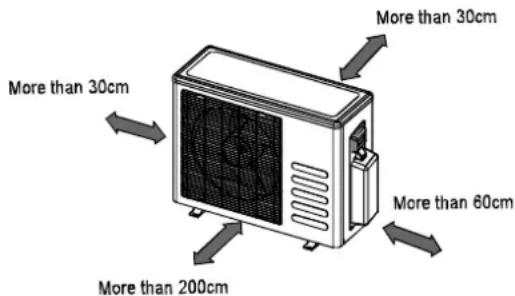
Fig.2
- Do not place animals and plants in the path of the air inlet or outlet.
- Take the air conditioner weight into account and select a place where noise and vibration will not be an issue.
- Select a place so that the warm air and noise from the air conditioner do not disturb neighbors.
Rooftop installation:
- If the outdoor unit is installed on a roof structure, be sure to level the unit.
- Ensure the roof structure and anchoring method are adequate for the unit location.
- Consult local codes regarding rooftop mounting.
- If the outdoor unit is installed on roof structures or external walls, this may result in excessive noise and vibration, and may also be classed as a non serviceable installation.
Tools needed for installation:
Level gauge
Screwdriver
Electric drill, Hole core drill ( 65mm)
Flaring tool set
Specified torque wrenches: 1.8kgf.m, 4.2kgf.m,
5.5kgf.m, 6.6kgf.m(different depending on model No.)
Spanner (half union)
Hexagonal wrench (4mm)
Gas-leak detector
Vacuum pump
Gauge manifold
Users manual
Thermometer
Multimeter
Pipe cutter
Measuring tape
Accessories
| Number | Name of Accessories | Q' ty/one unit | |||
| 1 | Installation Plate | 1 | |||
| 2 | Plastic Expansion Sheath | 5-8 (depending on models) | |||
| 3 | Self-tapping Screw A ST3.9X25 | 5-8 (depending on models) | |||
| 4 | Connecting pipe Assembly | Liquid side | Φ6.35 | Parts you must purchase Consult the technician for the proper size. | |
| Gas side | Φ9.53 | ||||
| Φ12.7 | |||||
| 5 | Remote controller | 1 | |||
| 6 | Self-tapping Screw B ST2.9X10 | Optional parts | 2 | ||
| 7 | Remote controller holder | 1 | |||
| 8 | Seal (for cooling& heating models only) | 1 | |||
| 9 | Drain Joint (for cooling& heating models only) | 1 | |||
| 10 | Transfer connector(Packed with the indoor unit) (NOTE: Pipe size differ from appliance to appliance. To meet different pipe size requirement, sometimes the pipe connections need the transfer connector to install on the outdoor unit.) | 1-4 (on some models) | |||
| 11 | Magnetic ring | 1 | |||
Note: Except the above parts provided, the other parts needed during installation you must purchase.
![graph TD A["One-Two"] --> B["One-Three"] B --> C["One-Four"] C --> D["One-Five"] D --> E["Loop a connective cable"] subgraph Air_Circuit F1["Two air filters"] --> G1["Three remote controller"] F2["Air filter"] --> G2["Four remote controller"] end subgraph Air_Out H1["Air out"] --> I1["5 Remote contr…](/content/2026/05/1038239/images/203d2dd77d0031cfff60e37f60d4d0064453a4dc4368078879c3877d0520cb9f.jpg)
Fig.3

CAUTIONS
- This illustration is for explanation purposes only. The actual shape of your air conditioner may be slightly different.
• Copper lines must be insulated independently
CAUTION
- Use a stud finder to locate studs to prevent unnecessary damage to the wall.
- A minimum pipe run of 3 metres is required to minimise vibration & excessive noise.
- Two of the A, B and C directions should be free from obstructions.
Indoor unit installation(wall-mounted type)
1. Fit the Installation Plate
- Fit the installation plate horizontally on structural parts of the wall with spaces around the installation plate.
- If the wall is made of brick, concrete or the like, drill eight (8) 5mm diameter holes in the wall. Insert Clip anchor for appropriate mounting screws.
- Fit the installation plate on the wall with eight (8) type "A" screws.
Note:
Fit the Installation Plate and drill holes in the wall according to the wall structure and corresponding mounting points on the installation plate. The Installation Plate may be slightly different according to the different models of indoor unit.
(Dimensions are in "mm" unless otherwise stated)
Correct orientation of Installation Plate

Fig.4
150mm or more to ceiling

Model A (A: 710, B: 250, C: 100, D: 110)
Model B(A: 790, B: 265, C: 100, D: 150)

Model A(A:710, B:250, C:100, D:110)
Model B(A:790, B:275, C:100, D:85)
Model C(A:850, B:290, C:100, D:115)

Model A (A: 920, B: 293, C: 150, D: 185)
Model B(A:995, B:293, C:150, D:200)
Model C(A:850, B:305, C:150, D:145)
Fig.5

Fig.6

Do not block water flow by a rise.
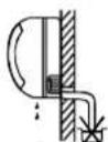
Do not put the end of drain hose into water.
Fig.7
2. Drill a hole in the wall
- Determine hole positions according to the diagramdetailed in Fig.5. Drill one (1) hole ( 65mm) slanting slightly to outdoor side.
- Always use wall hole conduit when drilling metal grid, metal plate or the like.
3. Connective Pipe and Drainage Installation Drainage
-
Run the drain hose sloping downward. Do not install the drain hose as illustrated in Fig.7.
-
When connecting extension drain hose, insulate the connecting part of extension drain hose with a shield pipe, do not let the drain hose slack.
Connective pipe installation
- For the left-hand and right-hand piping, remove the pipe cover from the side panel.
- For the rear-right-hand and rear-left-hand piping, install the piping as shown in Fig.10.
- Fix the end of the connective pipe. (Refer to Tightening Connection in REFRIGERANT PIPING CONNECTION)

Fig.8
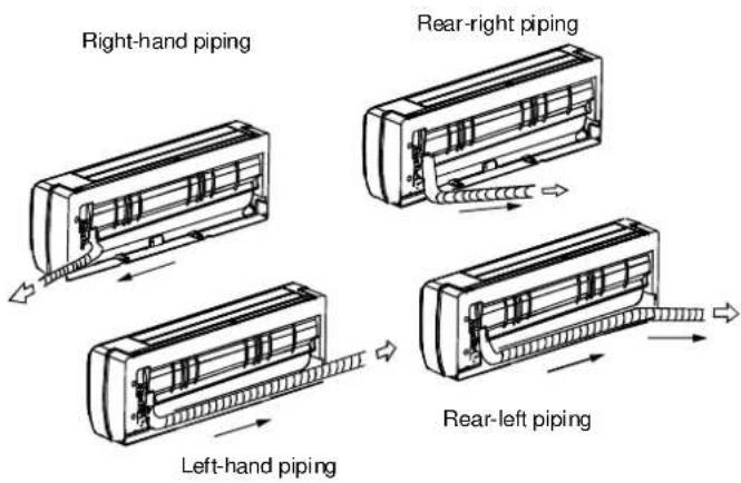
Fig. 9
Fig.10
4. Piping and wrapping
Bundle the tubing, connecting cable, and drain hose with tape securely, evenly as shown in Fig.11.
- Because the condensed water from rear of the indoor unit is gathered in ponding box and is piped out of room. Do not put anything else in the box.
CAUTION
- Connect the indoor unit first, then the outdoor unit.
- Do not allow the piping to let out from the back of the indoor unit.
- Be careful not to let the drain hose slack.
- Heat insulated both of the auxiliary piping.
- Be sure that the drain hose is located at the lowest side of the bundle. Locating at the upper side can cause drain pan to overflow inside the unit.
- Never intercross nor intertwist the power wire with any other wiring.
- Run the drain hose sloped downward to drain out the condensed water smoothly.

Fig.11
4. Indoor unit installation
- Pass the piping through the hole in the wall.
- Put the upper claw at the back of the indoor unit on the upper hook of the installation plate, move the indoor unit from side to side to see that it is securely hooked (see Fig.12).
- Piping can easily be made by lifting the indoor unit with a cushioning material between the indoor unit and the wall. Get it out after finish piping.
- Push the lower part of the indoor unit up on the wall, then move the indoor unit from side to side, up and down to check if it is hooked securely.
| Indoor units that can be used in combination | Number of connected units | 1-5units | |
| Total of indoor units class KW | 10.5KW | ||
| Total length for all rooms | Max. 75m (R410A) | Max. 50m (R407c/R22) | |
| Length for one indoor unit | Max. 15m (R410A) | Max.10m (R407c/R22) | |
| Difference in height between indoor and outdoor units | When above outdoor unit (B) | Max. 10m | |
| When below outdoor unit (A) | Max. 10m | ||
| Difference in height between indoor units | Max.5m | ||
| Compressor stop/start frequency | 1 cycle time | 6 min or more (from stop to stop or from start to start) | |
| Stop time | 3 min or more | ||
| Power source voltage | Voltage fluctuation | within ±10% of rated voltage | |
| Voltage drop during start | within ±15% of rated voltage | ||
| Interval unbalance | within ±3% of rated voltage | ||


Fig.12
2. Four-way cassette type
Attached fittings
Please check whether the following fittings are of full scope. If there are some attached fittings free from use, please restore them carefully.
| Installation Fittings | Tubing & Fittings | Remote controller & Its Frame(on some models) |
1. Expansible hook......42. Installation hook...... 3. Installation paper board......14. Bolt M5×16 or M6×12......45. Magnetic ring......1 3. Installation paper board......14. Bolt M5×16 or M6×12......45. Magnetic ring......1 | 6. Connecting pipe group......17. Binding tape......68. Soundproof / insu  eath......2 eath......2 | 9. Remote controller......1 10. Frame......1 10. Frame......1 11. Mounting screw(ST2.9×10-C-H) ...212. Alkaline dry batteries (AM4)......2 11. Mounting screw(ST2.9×10-C-H) ...212. Alkaline dry batteries (AM4)......2 |
Notes before installation
- Decide the correct carry-in path.
- Move this unit as originally packaged as possible.
- If the air conditioner is installed on a metal part of the building, it must be electrically insulated according to the relevant electrical code.
- If installing in a lonely building or at a high position where it is hot and humid with frequent thunderstorm, lightning-protection equipment is necessary.
Indoor unit installation
1. Install the main body
A. The existing ceiling (to be horizontal)
a. Please cut a quadrangular hole of 600 × 600mm in the ceiling according to the shape of the installation paper board. (Refer to Fig.15 & 16)
- The center of the hole should be at the same position of that of the air conditioner body.
- Determine the lengths and outlets of the connecting pipe, drain pipe and cables.
- To balance the ceiling and to avoid vibration, please enforce the ceiling when necessary.
b. Please select the position of installation hooks according to the hook holes on the installation board.
- Drill four holes of 12mm , 50 55mm deep at the selected positions on the ceiling. Then embed the expansible hooks(fittings).
- Face the concave side of the installation hooks toward the expansible hooks. Determine the length of the installation hooks from the height of ceiling, then cut off the unnecessary part.
- If the ceiling is extremely high, please determine the length of the installation hook according to facts.
- Cut the installation hook open in the middle position, then use appropriate length of reinforcing rod ( φ 12) to weld together.
Necessary room

Fig.13
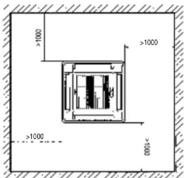
Fig.14

Fig.15
The length could be calculated from Fig.17:
Length=210+L(in general, L is half of the whole length of the installation hook)
c. Please adjust the hexangular nuts on the four installation hooks evenly, to ensure the balance of the body.
- Use the transparent hose filled with water to check the lever of the main body from the four sides or diagonal line direction, the lever indicator also can check the lever from four sides of the main body .(Refer to Fig.18)
- If the drainpipe is awry, leakage will be caused by the malfunction of the water-level switch.
- Adjust the position to ensure the gaps between the body and the four sides of ceiling are even.
- The body's lower part should sink into the ceiling for 10\~12mm (Refer to Fig.17).
- Locate the air conditioner firmly by wrenching the nuts after having adjusted the body's position well.
New built houses and ceilings
a. In the case of new built house, the hook can be embedded in advance (refer to the A.b mentioned above). But it should be strong enough to bear the indoor unit and will not become loose because of concrete shrinking.
b. After installing the body, please fasten the installation paper board onto the air conditioner with bolts (M5×16) to determine in advance the sizes and positions of the hole opening on ceiling. Please
, first guarantee the flatness and horizontal of ceiling when installing it. Refer to the A.a mentioned above for others.
c. Refer to the A.c mentioned above for installation.
d. Remove the installation paper board.
2. Install The Panel CAUTIONS
- Never put the panel face down on floor or against the wall, or on bulgy objects.
- Never crash or strike it.
(1) Remove the inlet grid.
a. Slide two grid switches toward the middle at the same time, and then pull them up. (Refer to Fig.21)
b. Draw the grid up to an angle of about 30° , and remove it. (Refer to Fig.22)

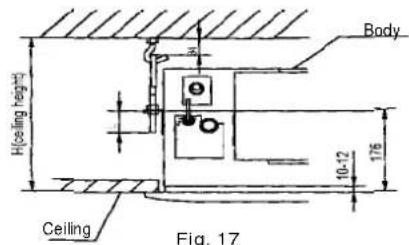

Fig.18

Fig.19


Fig.21

Fig.22
(2) Install the panel
a. Align the swing motor on the panel to the water receiver of the body properly. (Refer to Fig.23)
b. Hang the four fixed rope of the main body to the installation cover and the other three covers of the swing motor: (Refer to Fig.23)
CAUTIONS:
The installation cover of the swing motor must sink into the corresponding water receiver.
c. Install the panel on the main body with bolt (M5×16) and washer. (Refer to Fig.23)
d. Adjust the four panel hook screws to keep the panel horizontal, and screw them up to the ceiling evenly.
e. Regulate the panel in the direction of the arrow in Fig.11 slightly to fit the panel's center to the center of the ceiling's opening. Guarantee that hooks of four corners are fixed well.
f. Keep fastening the screws under the panel hooks, until the thickness of the sponge between the body and the panel's outlet has been reduced to about 4\~6mm. The edge of the panel should contact with the ceiling well. (Refer to Fig.24) Malfunction described in Fig.25 can be caused by inappropriate tightness the screw. If the gap between the panel and ceiling still exists after fastening the screws, the height of the indoor unit should be modified again. You can modify the height of the indoor unit through the openings on the panel's four corners, if the lift of the indoor unit and the drainpipe is not influenced (refer to Fig.26-right).
(3) Hang the air-in grid to the panel, then connect the lead terminator of the swing motor and that of the control box with corresponding terminators on the body respectively.
(4) Relocate the air-in grid in the procedure of reversed order, install the air-in grid.

Fig.23

Fig.24
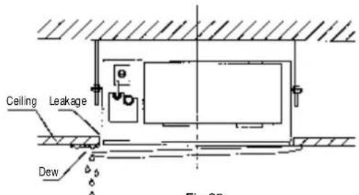
Fig.25
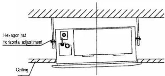
Fig.26
3. Duct & Ceiling type
Installation precautions
-
Determine the moving route.
-
Move the unit in original state.
-
Make sure to do electric insulation according to relevant electric standard in case the unit is installed on metal part of building.
-
Please keep away from the following places, or malfunction may be caused. (if unavoidable, please consult the professionals):
A. There is mineral oil like the oil of cutting machine.
B. There is much salty air. (Near the coast)
C. There is caustic gas such as sulfuric gas. (Near the hotspring.)
D. Factory where the voltage fluctuate greatly.
E. In the car or in the cabin.
F. In the kitchen or a place full of oil steam..
G. There is strong electromagnetic wave.
H. There is combustible gas or materials.
I. There is much evaporating acid or alkaline gas.
J. Other special areas.
Accessories
| NO | Name | Qty. | Outline | Function |
| 1 | Insulation pipe | 2 | Pipe joint heat insulation | |
| 2 | Remote controller | 1 | — | Remote control air conditioner |
| 3 | Big washer | 8 | — | Overhang indoor unit |
| 4 | Constriction bandage | 10 | — | Binding insulation pipe |
| 5 | Water outlet joint (for cool/heat type only) | 1 | — | Outdoor unit drainage |
| 6 | Gasket (for cool/heat type only) | 1 | — | Outdoor unit drainage |
| 7 | Copper nut | 2 | — | Connecting pipe |
| 8 | Drain hose | 1 | — | Indoor unit drainage |
| 9 | 7# Alkaline battery | 1 | — | — |
| 10 | Remote signal receiver subassembly | 1 | — | — |
| 11 | Magnetic ring | 1 | — | — |
Indoor unit installation
Installation location
- Enough room for installation and maintenance.


- The ceiling is horizontal and it can afford the weight of the indoor unit.
● The air inlet and outlet are not impeded and does not affected by outdoor air too much.
●The air flow can reach every part of the room.
● The connecting pipe and drainpipe can be easily extracted out.
● There is no direct radiation from heat source.

Installation of unit
Install φ 10 (4 pieces) hanging screw bolt
● Determine the location of hanging screw bolt following Fig.33.
● Make sure to use the hanging screw bolt of φ 10.
● The treatment to the ceiling varies from construction; please consult the professionals for details.
1) Treatment to ceiling---make sure to consolidate the roof beam for possible vibration to keep the ceiling horizontal.
2) Please cut off the roof beam.
3) Reinforce the place that is cut off and consolidate the roof beam.
- Carry out connection of piping and wiring inside the ceiling.
- Determine the piping direction. Especially in the case of existing ceiling, please pull the wire to the connection place before overhanging the unit.
Install the hanging bolt in following different situation:
Wooden structure
Put a timber across the beams and install the bolts.
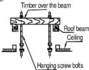
Fig.27
Original concrete bricks
Install the hanging hook with expansible bolt into the concrete.

Fig.28
New concrete bricks
Install with insertion or embedding screw.
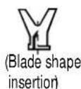

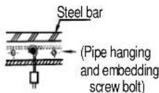
Fig.29
Steel roof beam structure
Install the supporting angle steel.
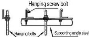
Fig.30
Overhang the unit
- Install the hanging screw bolt to the U-shaped slot of installation ear. Overhang the indoor unit and measure the level degree of unit with a gradienter.
- Fasten and fix the upside nut.
Hanging screw bolt

Fig.31

Fig.32
INSTALLATION INSTRUCTIONS
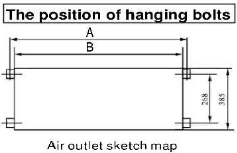

| MODEL | A B | C D | ||
| <12000Btu/h | 915 | 870 | 715 | 870 |
| >12000Btu/h | 1260 | 1224 | 1015 | 1215 |
Air Inlet Panel of Air Return Box
CAUTION
- Make the air inlet grille and air inlet direction in parallel as shown in Fig. 34a. Fig.34b is incorrect, which may cause loud noise.
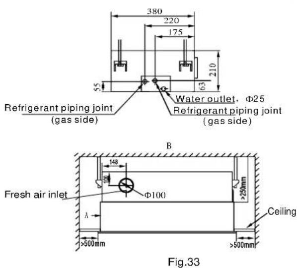

Drainpipe installation
- Indoor unit drainpipe installation
Piping, insulation material
| Piping | Hard PVC pipe |
| Insulation material | Cellular polyethylene, thicker than 6mm |
Drainage
See Fig.35.
Heat insulation
- Please do heat insulation on piping joint.
- Bind the contact insulation part between the unit and installation location with bandage.


CAUTION
- The drain pipe as well as the connection part of indoor unit must be heat insulated, or condensate will occur.
- Please connect the pipe with horny PVC bond and make sure there is no leakage.
- Do not impose the pressure on connecting part of drainpipe.
- The gradient downwards of drain pipe should be over 1/100, and do not bend the drain pipe.
- Pull the drain pipe transversely within 20m. Please install a supporter in case the drainpipe is very long to prevent it from bending.
- Refer to the figures on the right for the installation of pipes.
Instructions for duct installation accessories Duct design
Make the duct as short as possible due to the low static pressure (nearly 0 pa) of this unit.
Fix installation board
Fix the installation board on duct outlet with the bolts in accessories. If the bolt is self-provided, the length of bolt should be appropriate and make sure not to damage the inside of unit. See Fig.30
Duct installation
Fix the duct on installation board with rivet.
See Fig.41.
NOTE:
- Do not let the indoor unit bear the weight of duct.
- For convenient maintenance, install the duct at the place where it is easy to do removing.
- In case doing installation in meeting room or such places, please equip the interior with liner and muffler.
- These accessories are optional. Please contact the service for other requirement.
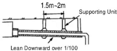
Fig.37

Fig.38

Fig.39

Fig.40

Fig.41
Accessories
| Name | Qty. | Outline/specification | Function |
| Duct installation board | 8 | Connecting duct | |
| Fixation bolt (fixing installation board) | 8 | ST3.9 × 10-F-H | Fixing duct installation board |
4. Ceiling and Floor type
4.1 Accessories
| Name of Accessories | Q'ty | Outline | Usage |
| Owner's manual | 1 |  | — |
| Installation manual | 1 | (This manual) | — |
| Hook | 2 |  | For wall mounting installation |
| Hanging arm | 2 |  | For ceiling installation |
| Magnetic ring | 1 |  | For wire connection |
| Remote Controller & Its Frame(on some models) |
1. Remote controller......1 2. Frame......1 2. Frame......1 3. Mounting screw(ST2.9x10-C-H)......2 3. Mounting screw(ST2.9x10-C-H)......2 4. Alkaline dry batteries(AM4)......2 4. Alkaline dry batteries(AM4)......2 |
Cautions on remote controller installation
- Never throw or beat the controller.
- Before installation, operate the remote controller to determine its location in a reception range.
- Keep the remote controller at least 1m apart from thenearest TV set or stereo equipment. (It is necessary to prevent image disturbances or noise interferences.)
- Do not install the remote controller in a place exposed to direct sunlight or close to a heating source, such as a stove.
Note that the positive and negative poles are in right positions when loading batteries.
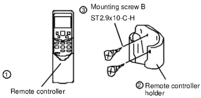
Fig.42-1
4.2 Indoor unit installation
1. Installing φ 10 hanging screw bolts (4 bolts).
- Please refer to the following figure for the distance measurement between the screw bolts.
- Please install with 10 hanging screw bolts.
- The handling to the ceiling varies from the constructions, consult the construction personnels for the specific procedures.
- The size of the ceiling to be handled----do keep the ceiling flat. Consolidate the roof beam for possible vibration.
-Cut off the roof beam.
–Strengthen the place cut off, and consolidate the roof beam.
- Carry out the pipe and line operation in the ceiling after finishing the installation of the mainbody. While choosing where to start the operation, determine the direction of the pipes to be drawn out. Especially in case there is a ceiling, position the refrigerant pipes, drain pipes, indoor & outdoor lines to the connection places before hanging up the machine.
• The installation of hanging screw bolts.
2. Wooden construction
Put the square timber traversely over the roof beam, then install the hanging screw bolts. (Refer to Fig.42-2)
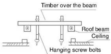
Fig.42-2
3. New concrete bricks
Inlaying or embedding the screw bolts. (Refer to Fig.42-3)

(Blade shape insertion)

(Slide insertion)
Fig.42-3
4. For original concrete bricks
Use embedding screw bold, crock and stick harness (Refer to Fig.42-4).

Fig.42-4
5. Steel roof beam structure
Install and use directly the supporting angle steel. (Refer to Fig.42-5)

Fig.42-5
4.3 Wall Mounting Installation

Fig.42-6
- Fix the hook with tapping screw onto the wall. (Refer to Fig.42-7)
- Hang the indoor unit on the hook.

Fig.42-7
4.4 Ceiling Installation

Fig.42-8
- Remove the side board and the grille. (Refer to Fig.42-9) (For 48000Btu/h and 60000Btu/h models, do not remove the grille.)
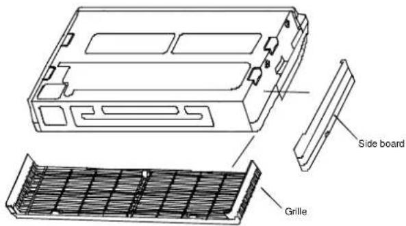
Fig.42-9
- Location the hanging arm on the hanging screw bolt. (Refer to Fig.42-10) Prepare the mounting bolts on the unit. (Refer to Fig.42-11)

Fig.42-10

Fig.42-11
- Hang the unit on the hanging arm by sliding backward. Securely tighten the mounting bolts on both sides. (Refer to Fig.42-12)

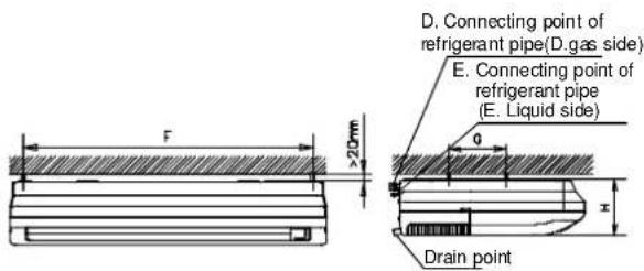
Fig.42-12
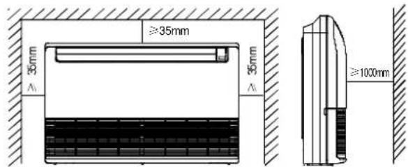
Fig.42-13
CAUTION
The figures above are based on model with 18000Btu/h as rated capacity, which may differ from the unit you purchased.
4.5 The Dimension of the Unit
Unit:mm
| Capacity | A | B D | E C | F G | H | |||
| 12 18- | 990 | 660 | 206 | 505 | 506 | 907 | 200 | 203 |
Note: The dimension of 12000Btu/h and 18000Btu/h are the same.
5. Floor and Standing Type (Console)
5.1 Accessories(Console)
Please check whether the following fittings are of full scope. If there are some spare fittings, please restore them carefully.
| Installation fittings | NAME | SHAPE | QUANTITY |
| 1.Hook |  | 2 | |
| 2. Magnetic ring |  | 1 | |
| Remote controller & Its Frame (on some models) | 3. Remote controller |  | 1 |
| 4. Frame |  | 1 | |
| 5. Mounting screw (ST2.9 10-C-H) |  | 2 | |
| 6. Alkaline dry batteries (AM4) |  | 2 | |
| Others | 7. Owner's manual | —— | 1 |
| 8. Installation manual | —— | 1 |
Cautions on remote controller installation:
- Never throw or beat the controller.
- Before installation, operate the remote controller to determine its location in a reception range.
- Keep the remote controller at least 1m apart from the nearest TV set or stereo equipment. (it is necessary to prevent image disturbances or noise interferences.)
- Do not install the remote controller in a place exposed to direct sunlight or close to a heating source, such as a stove.
- Note that the positive and negative poles are right positions when loading batteries.
- This manual is subject to changes due to technological improvement without further notices.

Fig.43-1
5.2 Inspecting and Handling the unit(Console)
At delivery, the package should be checked and any damage should be reported immediately to the service agent. When handling the unit, take into account the following:
- Fragile, handle the unit with care.
- Keep the unit upright in order to avoid compressor damage.
- Choose on before hand the path along which the unit is to be brought in.
- Move this unit as originally package as possible.
- When lifting the unit, always use protectors to prevent belt damage and pay attention to the position of the unit's centre of gravity.
5.3 Indoor Unit Installation(Console)
5.3.1 Installation place
The indoor unit should be installed in a location that meets the following requirements:
- There is enough room for installation and maintenance. (Refer to Fig.43-2 & Fig.43-3)
- The outlet and the inlet are not impeded, and the influence of external air is the least.
- The air flow can reach throughout the room.
- The connecting pipe and drainpipe could be extracted out easily.
- There is no direct radiation from heaters.

CAUTION
Keep indoor unit, outdoor unit, power supply wiring and transmission wiring at least 1 meter away from televisions and radios. This is to prevent image interference and noise in those electrical appliances. (Noise may be generated depending on the conditions under which the electric wave is generated, even if 1 meter is kept.)

Fig.43-2


Fig.43-3
5.3.2 Install the main body
● Fix the hook with tapping screw onto the wall. (Refer to Fig.43-4)

Fig.43-4
- Hang the indoor unit on the hook. (The bottom of body can touch with floor or suspended, but the body must install vertically.)

Fig.43-5
5.4 Install the connecting pipe (Console)
Check whether the height drop between the indoor unit and outdoor unit, the length of refrigerant pipe, and the number of the bends meet the following requirements:
| Capacity(KBtu/h) | 7/9/12 | 18/20/26/32/53 |
| The max height drop | 5m | 10m |
| The length of refrigerant pipe | Less than 10m | Less than 20m |
| The number of bends | Less than 5m | Less than 5 |
5.4.1 The procedure of connecting pipes:

CAUTION
- All field piping must be provided by a licensed refrigeration technician and must comply with the relevant local and national codes.
- Do not let air, dust, or other impurities fall in the pipe system during the time of installation.
- The connecting pipe should not be installed until the indoor and outdoor units have been fixed already.
- Keep the connecting pipe dry, and do not let moisture in during installation.
-
Execute heat insulation work completely on both sides of the gas piping and the liquid piping. Otherwise, this can sometimes result in water leakage.
-
Drill a hole in the wall (suitable just for the size of the wall conduit), then set on the fittings such as the wall conduit and its cover.
- Bind the connecting pipe and the cables together tightly with binding tapes. Pass the bound connecting pipe through the wall conduct from outside. Be careful of the pipe allocation to do on damage to the tubing.
- Connect the pipes. Refer to "How to Connect the pipes" for details.
- Expel the air with a vacuum pump. Refer to "How to expel the air with a vacuum pump" for details.
- open the stop values of the outdoor unit to make the refrigerant pipe connecting the indoor unit with the outdoor unit in fluent flow.
- Check the leakage. Check all the joints with the leak detector or soap water.
- Cover the joints of the connecting pipe with the soundproof / insulating sheath (fittings), and bind it well with the tapes to prevent leakage.

CAUTION
Be sure to with insulating materials cover all the exposed parts of the flare pipe joints and refrigerant pipe on the liquid-side and the gas-side. Ensure that there is no gap between them. Incomplete insulation may cause water condensation.
How to take indoor unit apart to connect the pipes
1. Open the front panel
- Slide the two stoppers on the left and right sides inword until they click. See Fig.43-6.

Fig.43-6
2. Remove the front panel
- Remove the string. (Refer to Fig.43-7).
- Allowing the front panel to fall forward will enable you to remove it.

Fig.43-7
3. Remove the face plate
- Remove the four screws.(Refer to Fig.43-7).
- Opening bottom of face plate for a angle that is 30 degrees, then the top of face plate will be take up.(Refer to Fig.43-8)

Fig.43-8
5.5 Connect the drain pipe(Console)
■ Install the drain pipe of the indoor unit
The outlet has PTI screw bread, Please use sealing materials and pipe sheath(fitting) when connecting PVC pipes.

CAUTION
● The drain pipe of indoor unit must be heat insulated, or it will condense dew, as well as the connections of the indoor unit.
● Hard PVC binder must be used for pipe connection, and make sure there is no leakage.
- With the connection part to the indoor unit, please be noted not to impose pressure on the side of indoor unit pipes.
- When the declivity of the drain pipe downwards is over 1/100, there should not be any winding.
- The total length of the drain pipe when pulled out traversely shall not exceed 20m, when the pipe is over long, a prop stand must be installed to prevent winding.
- Refer to the figures on the right for the installation of the pipes.

Fig.43-9
■ Drainage test
- Check whether the drain pipe is unhindered.
- New built house should have this test done before paving the ceiling.
5.6 Wiring(Console)
CAUTION
- The appliance shall be installed in accordance with national wiring regulations.
- The air conditioner should use separate power supply with rated voltage.
- The external power supply to the air conditioner should have ground wiring, which is linked to the ground wiring of the indoor and outdoor unit.
- The wiring work should be done by qualified persons according to circuit drawing.
-
An all-pole disconnection device which has at least 3mm separation distance in all pole and a residual current device(RCD)with the rating of above 10mA shall be incorporated in the fixed wiring according to the national rule.
-
Be sure to locate the power wiring and the signal wiring well to avoid cross-disturbance.
- Do not turn on the power until you have checked carefully after wiring.
5.6.1 Connect the cable
■The installation bearer of sensing device rotated to another side, and then takes off cover of electrical box. (Take off the electrical box if the capacity is 18000btu/h as well as using network function.) (Refer to Fig.43-10)
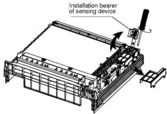
Fig.43-10
NOTE:
All the pictures in this manual are for explanation purpose only. They may be slightly different from the air conditioner you purchased(depend on model). The actual shape shall prevail.
Outdoor unit installation
Outdoor installation precaution
• Install the outdoor unit on a rigid base to prevent increasing noise level and vibration.
- Determine the air outlet direction where the discharged air is not blocked. In the case that the installation place is exposed to strong wind such as a seaside, make sure the fan operating properly by putting the unit lengthwise along the wall or using a dust or shield plates.
- Specially in windy area, install the unit to prevent the admission of wind. If need suspending installation, the installation bracket should accord with technique requirement in the installation bracket diagram.
- The installation wall should be solid brick, concrete or the same intensity construction, or actions to reinforce, damping supporting should be taken. The connection between bracket and wall, bracket and the air conditioner should be firm, stable and reliable.
- Be sure there is no obstacle which block radiating air.

Fig.44
Settlement of outdoor unit
- Anchor the outdoor unit with a bolt and nut φ 10 or φ 8 tightly and horizontally on a concrete or rigid mount.
| Outdoorunitdimension mm(L1xHxW1) | Mountingdimensions | |
| L2(mm) | W2(mm) | |
| 760x590x285 | 530 | 290 |
| 845x700x320 | 560 | 335 |
| 900x860x315 | 590 | 333 |
| 990x965x345 | 624 | 366 |


Fig.45
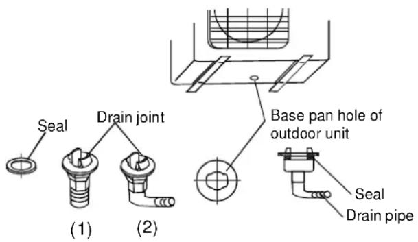
Drain joint installation
NOTE: The drain joint differ from appliance to appliance.
Fit the seal into the drain joint, then insert the drain joint into the base pan hole of outdoor unit, rotate 90° to securely assemble them.
Connecting the drain joint with an extension drain hose (Locally purchased), in case of the water draining off the outdoor unit during the heating mode.
Refrigerant pipe connection
1. Flaring work
Main cause for refrigerant leakage is due to defect in the flaring work.
Carry out correct flaring work using the following procedure:
A: Cut the pipes and the cable.
- Use the piping kit accessory or pipes purchased locally.
- Measure the distance between the indoor and the outdoor unit.
- Cut the pipes a little longer than the measured distance.
- Cut the cable 1.5m longer than the pipe length.
B: Burr removal
- Completely remove all burrs from the cut cross section of pipe/tube.
- Put the end of the copper tube/pipe in a downward direction as you remove burrs in order to avoid dropping burrs into the tubing.
C: Putting nut on
Remove flare nuts attached to indoor and outdoor unit, then put them on pipe/tube having completed burr removal.(not possible to put them on after flaring work)
Fig.46
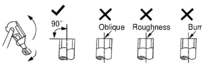
Fig.47
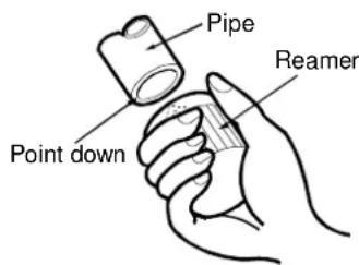
Fig.48

Fig.49
D: Flaring work
Firmly hold copper pipe in a die in the dimension shown in the table below.
| Outer diam. (mm) | A(mm) | |
| Max. | Min. | |
| φ 6.35 | 1.3 | 0.7 |
| φ 9.53 | 1.6 1.0 | |
| φ 12.7 | 1.8 | 1.0 |

Fig.50
Tightening Connection
- Align the center of the pipes.
- Sufficiently tighten the flare nut with fingers, and then tighten it with a spanner and torque wrench as shown in Fig.51 & 52.
| Outer diam. | Tightening torque(N.cm) | Additional tightening torque(N.cm) |
| φ 6.35 | 1500(153kgf.cm) | 1600(163kgf.cm) |
| φ 9.52 | 2500(255kgf.cm) | 2600(265kgf.cm) |
| φ 12.7 | 3500(357kgf.cm) | 3600(367kgf.cm) |
Caution
- Excessive torque can break nut depending on installation conditions.
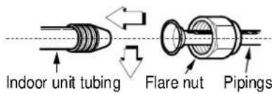
Fig.51

Fig.52
Electrical work
Electric safety regulations for the initial Installation
- If there is serious safety problem about the power supply, the technicians should refuse to install the air conditioner and explain to the client until the problem is solved.
- Power voltage should be in the range of 90%\~110% of rated voltage.
-
The creepage protector and main power switch with a 1.5 times capacity of Max. Current of the unit should be installed in power circuit.
-
Ensure the air conditioner is grounded well.
-
According to the attached Electrical Connection Diagram located on the panel of the outdoor unit to connect the wire.
-
All wiring must comply with local and national electrical codes and be installed by qualified and skilled electricians.
-
An individual branch circuit and single receptacle used only for this air conditioner must be available.
Wiring connection
NOTE: Before performing any electrical work, turn off the main power to the system.

CAUTIONS
- Do not touch the capacitor even if you have disconnected the power for there is still high voltage power on it, or electric shock hazard may occur. For your safety, you should start repairing at least 5 minutes later after the power is disconnected.
- The power is supplied from the Outdoor Unit. The four Indoor Unit are connected with a signal wires or power cords are connected reliably and correctly, or the air conditioner could not run normally.
Connect the cable to the outdoor unit
- Remove the electrical control board cover from the outdoor unit by loosening the screw as shown in Fig.51.
- Connect the connective cables to the terminals as identified with their respective matched numbers on the terminal block of indoor and outdoor units.
- Secure the cable onto the control board with the cord clamp.
- To prevent the ingress of water, from a loop of the connective cable as illustrated in the installation diagram of indoor and outdoor units.
- Insulate unused cords (conductors) with PVC-tape.Process them so they do not touch any electrical or metal parts.

CAUTIONS
Make sure to connect the indoor unit (A, B, C, D) to the Hi and Lo valve and terminals of signal wires (A, B, C, D) of outdoor unit as identified with their respective matched connection. Wrong wiring connections may cause some electrical parts to malfunction.
Minimum nominal cross-sectional area of conductors:
| Rated current of appliance (A) | Nominal cross-sectional area (mm2) |
| >3 and ≤6 | 0.75 |
| >6 and ≤10 | 1 |
| >10 and <16 | 1.5 |
| >16 and <25 | 2.5 |

Fig.53

Fig.54
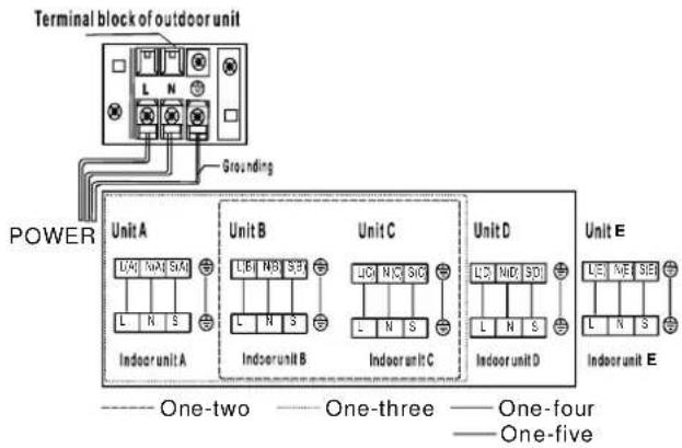
Fig.55
CAUTION
After the confirmation of the above conditions, prepare the wiring as follows:
1) Never fail to have an individual power circuit specifically for the air conditioner. As for the method of wiring, be guided by the circuit diagram posted on the inside of control cover.
2) The screw which fasten the wiring in the casing of electrical fittings are liable to come loose from vibrations to which the unit is subjected during the course of transportation. Check them and make sure that they are all tightly fastened. (If they are loose, it could cause burn-out of the wires.)
3) Specification of power source.
4) Confirm that electrical capacity is sufficient.
5) See to that the starting voltage is maintained at more than 90 percent of the rated voltage marked on the name plate.
6) Confirm that the cable thickness is as specified in the power source specification.
7) Always install an earth leakage circuit breaker in a wet or moist area.
8) The following would be caused by voltage drop.
Vibration of a magnetic switch, which will damage the contact point, fuse breaking, disturbance of the normal function of the overload.
9) The means for disconnection from a power supply shall be incorporated in the fixed wiring and have an air gap contact separation of at least 3mm in each active(phase) conductors.
Air purging
Air and moisture in the refrigerant system have undesirable effects as indicated below:
● Pressure in the system rises.
● Operating current rises.
● Cooling or heating efficiency drops.
● Moisture in the refrigerant circuit may freeze and block capillary tubing.
● Water may lead to corrosion of parts in the refrigeration system.
- Pressure in the system rises. - Operating current rises. - Cooling or heating efficiency drops. - Moisture in the refrigerant circuit may freeze and block capillary tubing. - Water may lead to corrosion of parts in the refrigeration system.
Therefore, the indoor unit and tubing between the indoor and outdoor unit must be leak tested and evacuated to remove any noncondensables and moisture from the system.
Air purging with vacuum pump
● Preparation
Check that each tube(both liquid and gas side tubes) between the indoor and outdoor units have been properly connected and all wiring for the test run has been completed. Remove the service valve caps from both the gas and the liquid side on the outdoor unit. Note that both the liquid and the gas side service valves on the outdoor unit are kept closed at this stage.
● Pipe length and refrigerant amount:
| Connective pipe length | Air purging method | Additional amount of refrigerant to be charged |
| Less than 5m | Use vacuum pump. | — |
| More than 5m | Use vacuum pump. | R22: (Pipe length-5m)x30g/mR410A: (Pipe length-5m)x15g/mR407c: (Pipe length-5m)x30g/m |
- When relocate the unit to another place, perform evacuation using vacuum pump.
- Make sure the refrigerant added into the air conditioner is liquid form in any case. (Not applicable to the units adopt freon R22)
Caution in handling the packed valve
- Open the valve stem until it hits against the stopper. Do not try to open it further.
- Securely tighten the valve stem cap with a spanner or the like.
- Valve stem cap tightening torque (See Tightening torque table in previous page).
When Using the Vacuum Pump
(For method of using a manifold valve, refer to its operation manual.)
- Completely tighten the flare nuts, A, B, C, D, connect the manifold valve charge hose to a charge port of the low-pressure valve on the gas pipe side.
- Connect the charge hose connection to the vacuum pump.
- Fully open the handle Lo of the manifold valve.
- Operate the vacuum pump to evacuate. After starting evacuation, slightly loose the flare nut of the Lo valve on the gas pipe side and check that the air is entering (Operation noise of the vacuum pump changes and a compound meter indicates 0 instead of minus)
- After the evacuation is complete, fully close the handle Lo of the manifold valve and stop the operation of the vacuum pump. Make evacuation for 15 minutes or more and check that the compound meter indicates -76cmHg (-1x10 5 Pa).
- Turn the stem of the packed valve B about 45° counterclockwise for 6\~7 seconds after the gas coming out, then tighten the flare nut again. Make sure the pressure display in the pressure indicator is a little higher than the atmosphere pressure.
- Remove the charge hose from the Low pressure charge hose.
- Fully open the packed valve stems B and A.
- Securely tighten the cap of the packed valve.
![graph LR A["Outdoor unit"] --> B["A"] B --> C["Refrigerant"] B --> D["B"] D --> E["Indoor unit"] C --> F["Liquid side"] D --> G["Half union"] style A fill:#f9f,stroke:#333 style B fill:#f9f,stroke:#333 style C fill:#ccf,stroke:#333 style D fill:#ccf,stroke:#333 style E fill:#cfc,stroke:#333](/content/2026/05/1038239/images/6c4531693ab2e9e7fdcbe5ae51e680151f0d6ca68e239cc64bfe60a195361254.jpg)
Fig.56

Fig.57
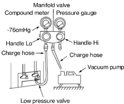
Fig.58
Safety and leakage check
● Electrical safety check
Perform the electric safe check after completing installation:
-
Insulated resistance The insulated resistance must be more than 2M Ω.
-
Grounding work After finishing grounding work, measure the grounding resistance by visual detection and grounding resistance tester. Make sure the grounding resistance is less than 4 Ω .
-
Electrical leakage check (performing during test running) During test operation after finishing installation, the serviceman can use the electroprobe and multimeter to perform the electrical leakage check. Turn off the unit immediately if leakage happens. Check and find out the solution ways till the unit operate properly.
● Gas leak check
1. Soap water method:
Apply a soap water or a liquid neutral detergent on the indoor unit connection or outdoor unit connections by a soft brush to check for leakage of the connecting points of th piping. If bubbles come out, the pipes have leakage.
2. Leak detector
Use the leak detector to check for leakage.
CAUTION
A: Lo packed valve B: Hi packed valve C and D are ends of indoor unit connection.
NOTE: The illustration is for explanation purpose only. The actual order of A, B, C D and E on the machine may be slightly different from the unit you purchased. The actual shape shall prevail.

a,b,c,d,h,i,j,k are points for one-two type. a,b,c,d,e,f,,h,i,j,k,m,n are points for one-three type.
Fig.59

A, B, C, D are points for one-four type. A, B, C, D, E are points for one-five type.
Fig.60
Test running
Perform test operation after completing gas leak check at the flare nut connections and electrical safety check.
- Check that all tubing and wiring have been properly connected.
-
Check that the gas and liquid side service valves are fully open.
-
Connect the power, press the ON/OFF button on the remote controller to turn the unit on.
- Use the MODE button to select COOL, HEAT, AUTO and FAN to check if all the functions works well.
-
When the amient temperature is too low(lower than 17° C), the unit cannot be controlled by the remote controller to run at cooling mode, manual operation can be taken. Manual operation is used only when the remote controller is disable or maintenance necessary.
-
Hold the panel sides and lift the panel up to an angle until it remains fixed with a clicking sound.
-
Press the Manual control button to select the AUTO or COOL, the unit will operate under Forced AUTO or COOL mode(see User Manual for details).
-
The test operation should last about 30 minutes.


Fig.61
The design and specifications are subject to change without prior notice for product improvement. Consult with the sales agency or manufacturer for details.
CS464-I
202000191053
20111208
- INSTALLATION MANUAL
- MAXICOOL
- SAFETY PRECAUTIONS
- INSTALLATION INSTRUCTIONS
- REFRIGERANT PIPE CONNECTION
- ELECTRICAL WORK
- AIR PURGING
- TEST RUNNING
- READ THIS MANUAL
- CAUTION
- WALL-MOUNTED TYPE
- SELECTING INSTALLATION PLACE
- INDOOR UNIT
- OUTDOOR UNIT
- ROOFTOP INSTALLATION
- TOOLS NEEDED FOR INSTALLATION
- CAUTIONS
- INDOOR UNIT INSTALLATION(WALL-MOUNTED TYPE)
- FIT THE INSTALLATION PLATE
- NOTE
- DRILL A HOLE IN THE WALL
- CONNECTIVE PIPE AND DRAINAGE INSTALLATION DRAINAGE
- CONNECTIVE PIPE INSTALLATION
- PIPING AND WRAPPING
- INDOOR UNIT INSTALLATION
- FOUR-WAY CASSETTE TYPE
- ATTACHED FITTINGS
- NOTES BEFORE INSTALLATION
- INSTALL THE MAIN BODY
- NEW BUILT HOUSES AND CEILINGS
- INSTALL THE PANEL CAUTIONS
- REMOVE THE INLET GRID
- INSTALL THE PANEL
- DUCT & CEILING TYPE
- INSTALLATION PRECAUTIONS
- INSTALLATION LOCATION
- INSTALLATION OF UNIT
- INSTALL Φ 10 (4 PIECES) HANGING SCREW BOLT
- WOODEN STRUCTURE
- ORIGINAL CONCRETE BRICKS
- NEW CONCRETE BRICKS
- STEEL ROOF BEAM STRUCTURE
- OVERHANG THE UNIT
- AIR INLET PANEL OF AIR RETURN BOX
- DRAINPIPE INSTALLATION
- DRAINAGE
- HEAT INSULATION
- INSTRUCTIONS FOR DUCT INSTALLATION ACCESSORIES DUCT DESIGN
- FIX INSTALLATION BOARD
- DUCT INSTALLATION
- CEILING AND FLOOR TYPE
- 4.1 ACCESSORIES
- CAUTIONS ON REMOTE CONTROLLER INSTALLATION
- 4.2 INDOOR UNIT INSTALLATION
- INSTALLING Φ 10 HANGING SCREW BOLTS (4 BOLTS)
- WOODEN CONSTRUCTION
- FOR ORIGINAL CONCRETE BRICKS
- 4.3 WALL MOUNTING INSTALLATION
- 4.5 THE DIMENSION OF THE UNIT
- FLOOR AND STANDING TYPE (CONSOLE)
- 5.1 ACCESSORIES(CONSOLE)
- 5.2 INSPECTING AND HANDLING THE UNIT(CONSOLE)
- 5.3 INDOOR UNIT INSTALLATION(CONSOLE)
- 5.3.1 INSTALLATION PLACE
- 5.3.2 INSTALL THE MAIN BODY
- 5.4 INSTALL THE CONNECTING PIPE (CONSOLE)
- 5.4.1 THE PROCEDURE OF CONNECTING PIPES
- HOW TO TAKE INDOOR UNIT APART TO CONNECT THE PIPES
- OPEN THE FRONT PANEL
- REMOVE THE FRONT PANEL
- REMOVE THE FACE PLATE
- 5.5 CONNECT THE DRAIN PIPE(CONSOLE)
- INSTALL THE DRAIN PIPE OF THE INDOOR UNIT
- DRAINAGE TEST
- 5.6 WIRING(CONSOLE)
- 5.6.1 CONNECT THE CABLE
- OUTDOOR UNIT INSTALLATION
- OUTDOOR INSTALLATION PRECAUTION
- SETTLEMENT OF OUTDOOR UNIT
- DRAIN JOINT INSTALLATION
- FLARING WORK
- A: CUT THE PIPES AND THE CABLE
- B: BURR REMOVAL
- C: PUTTING NUT ON
- D: FLARING WORK
- TIGHTENING CONNECTION
- WIRING CONNECTION
- CONNECT THE CABLE TO THE OUTDOOR UNIT
- AIR PURGING WITH VACUUM PUMP
- CAUTION IN HANDLING THE PACKED VALVE
- WHEN USING THE VACUUM PUMP
- SAFETY AND LEAKAGE CHECK
- ● ELECTRICAL SAFETY CHECK
- ● GAS LEAK CHECK
- SOAP WATER METHOD
- LEAK DETECTOR
Marke : Maxicool
Modell : MMD2-18HDI
Kategorie : Klimaanlage