
MC-E455 - Staubsauger PANASONIC - Kostenlose Bedienungsanleitung
Finden Sie kostenlos die Bedienungsanleitung des Geräts MC-E455 PANASONIC als PDF.


| Marke | Panasonic |
| Modell | MC-E455 |
| Produkttyp | Staubsauger (Aufrecht) |
| Staubbeuteltyp | Papierbeutel Typ U-2E |
| Zentralfilter | Schaumstofffilter (AMC8F0391100) |
| Reinluftfilter | Elektrostatischer Filter (AMC8F28G1000) |
| Bürstenwalze | Ein-/Ausschaltbar mit Beater Bar Schalter |
| Griffverstellung | Fußpedal (3 Positionen: aufrecht, mittel, tief) |
| Kabelaufwicklung | Oberer und unterer Kabelhaken |
| Staubbeutelkontrollanzeige | Gelbe Markierung im Fenster |
| Zubehör | Schlauch, Düsen (Fugendüse, etc.) |
| Leistungsregelung | Nicht bei Modell MC-E455 (nur MC-E456/457) |
| Sicherheit | Thermosicherung, 13A Sicherung im Stecker |
| Antriebsriemen | Typ UB-1L |
| Kopflicht (optional) | Nur bei MC-E457 (Glühlampe AMC8D25B6100) |
| Gewicht (ca.) | 5,5 kg |
| Abmessungen (ca.) | Höhe: 110 cm, Breite: 30 cm, Tiefe: 25 cm |
Häufig gestellte Fragen - MC-E455 PANASONIC
Benutzerfragen zu MC-E455 PANASONIC
0 Frage zu diesem Gerät. Beantworten Sie die, die Sie kennen, oder stellen Sie Ihre eigene.
Eine neue Frage zu diesem Gerät stellen
Laden Sie die Anleitung für Ihr Staubsauger kostenlos im PDF-Format! Finden Sie Ihr Handbuch MC-E455 - PANASONIC und nehmen Sie Ihr elektronisches Gerät wieder in die Hand. Auf dieser Seite sind alle Dokumente veröffentlicht, die für die Verwendung Ihres Geräts notwendig sind. MC-E455 von der Marke PANASONIC.
BEDIENUNGSANLEITUNG MC-E455 PANASONIC
Operating Instructions
Vacuum Cleaner
MC-E455UK, MC-E456UK, MC-E457UK

natural_image
Line drawing of a vacuum cleaner on a tiled floor (no text or symbols)Panasonic
We would particularly advise that you carefully study this Operating Instructions before attempting to operate the unit and that you note the Important Safety Instructions. This product complies with the directives 73/23/EEC and 89/336/EEC.
TABLE OF CONTENTS
| Page | Page | ||
| • Caution for AC Mains Lead | 2 | • F) Beater bar switch | 7 |
| • Important Safety Instructions for the user | 3 | • G) How to use the accessories | 7 |
| • Cautions | 3 | • H) Dust bag check indicator | 8 |
| • Identification of main parts | 4 | • I) How to change the dust bag | 8 |
| • A) Handle assembly | 5 | • J) Filter care | 9 |
| • B) Power cord release / storage | 5 | • Trouble shooting guide | 9 |
| • C) ON/OFF Switch | 5 | • Blockages | 10 |
| • D) Variable power control | 6 | • Maintenance for the rotary brush | 10 |
| • E) Handle adjustment by foot pedal | 6 | • Servicing and repairs | 11 |

CAUTION FOR AC MAINS LEAD
FOR YOUR SAFETY PLEASE READ THE FOLLOWING TEXT CAREFULLY
This appliance is supplied with a moulded three pin mains plug for your safety and convenience.
A 13 amp fuse is fitted in this plug.
Should the fuse need to be replaced please ensure that the replacement fuse has a rating of 13 amps and that it is approved by ASTA or BSI to BS1362.
Check for the ASTA mark 🎨 or the BSI mark ♥ on the body of the fuse.
If the plug contains a removable fuse cover you must ensure that it is refitted when the fuse is replaced.
If you lose the fuse cover the plug must not be used until a replacement cover is obtained.
A replacement fuse cover can be purchased from your local Panasonic Dealer.
IF THE FITTED MOULDED PLUG IS UNSUITABLE FOR THE SOCKET OUTLET IN YOUR HOME THEN THE FUSE SHOULD BE REMOVED AND THE PLUG CUT OFF AND DISPOSED OF SAFELY.
THERE IS A DANGER OF SEVERE ELECTRICAL SHOCK IF THE CUT OFF PLUG IS INSERTED INTO ANY 13 AMP SOCKET.
If a new plug is to be fitted please observe the wiring code as shown below.
If in any doubt please consult a qualified electrician.
IMPORTANT: The wires in this mains lead are coloured in accordance with the following code:
Blue : Neutral
Brown : Live
As the colours of the wire in the mains lead of this appliance may not correspond with the coloured markings identifying the terminals in your plug, proceed as follows:
The wire which is coloured BLUE must be connected to the terminal in the plug which is marked with the letter N or coloured BLACK.
The wire which is coloured BROWN must be connected to the terminal in the plug which is marked with the letter L or coloured RED.
Under no circumstances should either of these wires be connected to the earth terminal of the three pin plug, marked with the letter E or the Earth Symbol 12
How to replace the Fuse:
- There are two types of the supplied AC Mains Lead: A and B as shown below.
1 Open the fuse compartment with a screwdriver.
2 Replace the fuse and fuse cover if detachable.

natural_image
Simple line drawing of a plug with wires, no text or symbols presentTYPE A

natural_image
Simple line drawing of a plug socket with two pins and a wire (no text or symbols)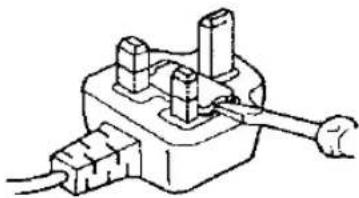
natural_image
Simple line drawing of a mechanical switch or electrical component with no text or symbolsTYPE B

natural_image
Technical line drawing of a power plug socket with terminal blocks (no text or symbols)Fuse cover Part No.: AMC8D48C0000.

IMPORTANT SAFETY INSTRUCTIONS FOR THE USER
When using this vacuum cleaner, please observe these basic precautions. WARNING: To reduce the risk of fire, electric shock, or injury:
- Do not leave the vacuum cleaner plugged in to mains outlet. Unplug from the outlet when not in use and before cleaning the appliance or undertaken maintenance operations.
- Electric shocks can occur if used outdoors or on wet surfaces.
• Make sure that hands and feet (particularly of small children) are kept away from the cleaner. - Do not use with damaged cord or plug. If the vacuum cleaner is not working as it should be, or has been dropped, damaged, left outdoors, or come into contact with water, consult an authorised Panasonic Service Centre.
- Do not pull or carry by cord, use cord as a handle, close a door on cord, pull cord around sharp edges or corners. Do not run vacuum cleaner over the cord. Keep cord away from heated surfaces.
- Do not handle plug or vacuum cleaner with wet hands.
- Do not put any object into openings. Do not use with any opening blocked; keep free of dust, lint, hair and anything that may block or reduce air flow.
- Keep hair, loose clothing, fingers, and all parts of body away from openings and moving parts.
- Do not use without dust bag and/or filters in place.
- Turn off all controls before unplugging.
- Use extra care when cleaning on stairs.
- Do not use to pick up flammable or combustible liquids such as gasoline or use in areas where they may be present.
- This appliance should be serviced by an authorised Panasonic Service Centre, and only genuine Panasonic spare parts should be used.
- Keep feet, fingers and hands away from the rotary brush. (It may cause injury).

CAUTIONS

- To avoid any possible damage to the mains cable, never run over the cord or allow it to become caught in the rotary brush when using the vacuum cleaner.

natural_image
Simple line drawing of crossed tools and a pencil (no text or symbols)- Before using the vacuum cleaner, remove large or sharp objects from the carpet to avoid damaging the machine or the dust bag.

natural_image
Simple line drawing of a crossed-out cigarette with a cup, no text or symbols present- Never let the vacuum cleaner pick up wet matter, mud or burning ashes, etc.

natural_image
Illustration of a rope knot and a circular object with cross mark (no text or symbols)- Do not pull on the cord strongly when disconnecting the appliance from the mains.

natural_image
Illustration of a vacuum cleaner next to a cart with a box and a cross symbol (no text or labels)- Keep the vacuum cleaner away from heat sources such as radiators, fires, direct sunlight, etc.

natural_image
Illustration of a hand using a pen to write on a mechanical component (no text or symbols visible)- Keep fingers and hands away from the rotary brush to avoid injury.
IDENTIFICATION OF MAIN PARTS

HOW TO ASSEMBLE / OPERATE YOUR CLEANER
A) HANDLE ASSEMBLY
natural_image
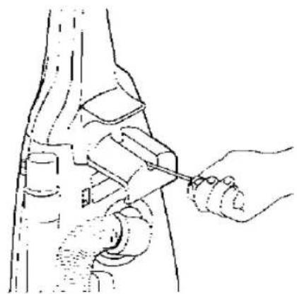
Line drawing of a hand using a tool to adjust or install a mechanical component (no text or symbols present)1) Insert the base of the handle into the top of the body of the machine as shown. Push in handle and tighten the screw.
IMPORTANT: Do not over tighten the screw.

2) Set the hose around the hose clip.

natural_image
Line drawing of a mechanical device with a handle and base, no visible text or symbols3) Turn the upper cord hook in the upright position and wind the power cord around the upper and lower cord hooks.
B) POWER CORD RELEASE / STORAGE

natural_image
Illustration of hands adjusting a rope or cable device (no text or symbols visible)1) Turn the upper hook to release the power cord for instant use.

natural_image
Illustration of a hand using a tool to lift or lift a mechanical component (no text or symbols visible)2) Fix the power cord by the cord clip to help secure the cord during use.
NOTE: To avoid any possible damage to the power cord, never run over the cord or allow it to become caught in the rotary brush.
C) ON / OFF SWITCH

To start or stop the vacuum cleaner push the switch button to "I" to turn ON and to "O" to turn OFF.
D) VARIABLE POWER CONTROL (MC-E456UK, MC-E457UK Only)
These vacuum cleaners incorporate a variable power control to select the most suitable power required for your cleaning needs.

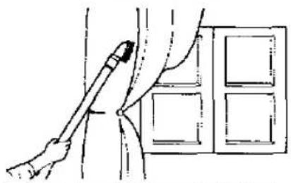
MIN: To clean curtains and soft furnishing's etc., with tool attached.
natural_image
Line drawing of a hand holding a tool near a window with a grid-patterned panel (no text or symbols)MAX: To clean with high suction continuously on carpets.

natural_image
Illustration of a hand pressing down on a mechanical component with textured surface (no text or symbols)E) HANDLE ADJUSTMENT BY FOOT PEDAL
To lower the body of the cleaner, step on the pedal at the left rear corner of the vacuum cleaner.

natural_image
Line drawing of a mechanical component with a hand operating it (no text or symbols)- Upright position
The handle should be in an upright position when cleaning tools are used.

natural_image
Line drawing of a car with extended exhaust pipe and fan (no text or symbols)- Middle position
For normal cleaning, depress the foot pedal and pull back the handle to a comfortable angle and release the pedal to lower the cleaning head.

natural_image
Line drawing of a car inside a vehicle, showing structural components and motion lines (no text or symbols)- Low position
For cleaning under furniture, depress the pedal a second time. The handle may now be lowered almost to the floor as shown.
E) BEATER BAR SWITCH
For cleaning carpeted floor, slide the switch to the "BEATER BAR" position. For using the accessories, slide the switch to the "STOP" position to stop the rotary brush from rotating.
NOTE: Always keep the vacuum cleaner operating in order to change rotary brush position.

natural_image
Line drawing of a hand operating a kitchen appliance with a curved handle (no text or symbols)SWITCH BEATER BAR ON OR OFF

G) HOW TO USE THE ACCESSORIES
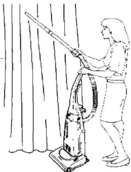
1) To use the accessories keep the vacuum cleaner in upright position and slide the beater bar switch to "STOP" position to stop the rotary brush rotating.
2) Pull out the hose from the rear side of the vacuum cleaner and remove the hose from the hose clip and support. Then connect any accessory as illustrated.
NOTE: After having finished using the accessories, re-insert the hose to the suction inlet and re-install the hose into the hose clip and support.

natural_image
Line drawing of a person using a vacuum cleaner to clean or clean curtains (no text or symbols)CAUTION: While using the accessories, hold the handle with one hand as shown above to avoid pulling the cleaner over.

natural_image
Technical line drawing showing two mechanical or electrical components with no visible text or symbolsH) DUST BAG CHECK INDICATOR
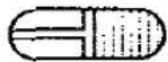
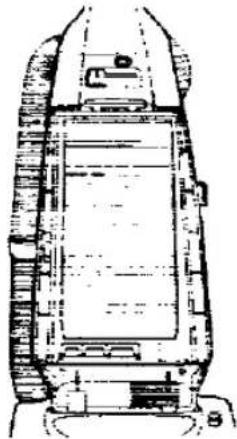
The dust bag check indicator (yellow mark) will appear in the window, when airflow through the bag is insufficient. When this happens, check the paper bag, it may be full or blocked with fine dust and needs to be replaced.
NOTE: If after having replaced the bag, the yellow mark continues appearing in the window, check to see if the hose or suction inlet is clogged. (see BLOCKAGES). Also the yellow mark can appears when using the crevice nozzle.
Yellow mark

natural_image
Technical line drawing of a mechanical component or assembly (no visible text or symbols)
natural_image
Top-down schematic of a vehicle or tank structure with no visible text or symbolsCAUTION: DISCONNECT THE CLEANER FROM THE MAINS OUTLET BEFORE THE OPERATIONS BELOW
1) HOW TO CHANGE THE DUST BAG

natural_image
Illustration of hands using a tool to adjust or install a mechanical component (no text or symbols visible)1) Remove dust cover simply pulling it forwards.

2) Grip the cardboard of the dust bag and pull out.

natural_image
Illustration of hands holding a device with visible circuit board (no text or symbols)3) Install the dust bag pressing the cardboard as shown and replace the dust cover. IMPORTANT: Dust bags should be changed regularly for maximum efficiency of vacuum cleaner.
NOTE: Make sure that the dust bag is correctly fitted to avoid dust leakage. We recommend the use of genuine Panasonic bags Type U-2E only.
-1) FILTER CARE

natural_image
Line drawing of a hand inserting a component into a device (no text or symbols visible)
natural_image
Line drawing of a hand inserting a component into a device (no text or symbols)
natural_image
Diagram of a hand pressing down on a grid-patterned mechanical component (no text or symbols)
natural_image
Hand inserting a grid into a device component (no text or symbols visible)Central Filter (Fig. 1)
Part no. AMC8F0391100
The central filter (foam filter) is installed in the dust bag compartment to protect the motor from dirt.
When it becomes dirty, simply rinse it out in warm water and dry it thoroughly before replacing.
To remove the central filter, hold the filter at the top (as illustrated) and pull it out.
Important: Ensure that the filter is completely dry before re-installing it into the cleaner.
Clean Air Filter (Fig. 2)
Part no. AMC8F28G1000
The clean air filter (electrostatic), is installed in the dust cover. This filter retains any small dust particles which may be present in the expelled air.
It is advisable to change the clean air filter when it becomes dirty. As a guide, once or twice a year is usually sufficient.
To change the clean air filter, first remove the dust cover and then slide out the filter support and simply unhook the filter from the retaining ribs.
NOTE: Never use the cleaner without the correct filters properly installed. Failure to do so may result in motor damaged.
IMPORTANT: Do not forget to re-install the filters before using the vacuum cleaner.
TROUBLE SHOOTING GUIDE
Before returning the vacuum cleaner to a Panasonic Service Centre, check the following points:
| Trouble | Check Point | Cause / Remedy |
| Motor fails to rotate (no noise is heard at all). | Mains plug connection.Mains plug fuse. | Mains plug connected firmly and mains outlet is on.Check fuse and replace if blown. |
| Motor runs but no suction. | Hose inlet clogged.Check dust indicator.Paper bag broken.Central filter. | If there is a blockage, remove it.If shows full, replace the paper bag.If paper bag is broken replace it.If the central filter is full of dust, clean or replace it. |
| Rotary brush does not rotate. | Clogged by a large object in the rotary brush housing.Belt broken / loose. | If there is any obstruction, remove it.If the belt is broken , replace it. If loose re-install it again. |
This vacuum cleaner is attached with a thermal-fuse device, that will operate when over heating occurs. If your cleaner does not work, it is possible that the over heating device has operated. If this occurs, take the vacuum cleaner to an official Panasonic Service Centre to be repaired.

IMPORTANT NOTE: Before servicing any part always,
DISCONNECT THE CLEANER FROM THE ELECTRICITY
BLOCKAGES
If your cleaner stops to pick up dust, or the dust bag check indicator shows "Full" while the dust bag is still empty, a blockage may have occurred.
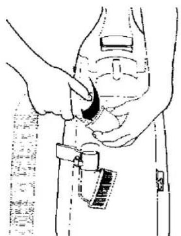
Remove the hose from the suction inlet, push the smalls clips inwards, turn the hose right and pull it upwards (Fig. 1). Clean any obstruction from the hose and/or suction inlet using a blunt implement, taking care not to damage the hose.
If the obstruction occurs in the suction pipe inlet, it can be removed with care as shown in Fig. 2.
natural_image
Illustration of a person adjusting a device on a device (no text or symbols visible)Fig. 1

natural_image
Illustration of hands adjusting a device with a black arrow pointing to the component (no text or symbols present)Suction pipe inlet

natural_image
Line drawing of hands operating a mechanical device with a tool (no text or symbols)Fig. 2
MAINTENANCE FOR THE ROTARY BRUSH
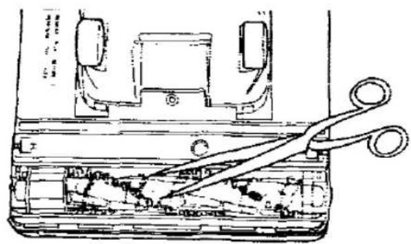
DO NOT USE YOUR FINGERS OR HANDS TO REMOVE OR CLEAN THE ROTARY BRUSH.
When it is necessary remove threads, strings, hairs, etc., which have wound around the rotary brush, cut across them with a pair of scissors making sure not to cut the brush.

natural_image
Technical line drawing of a mechanical device with scissors inserted into a housing (no text or symbols)SERVICING AND REPAIRS
Before replacing any part DISCONNECT THE CLEANER FROM THE MAINS SUPPLY. We always recommend you use genuine Panasonic replacement parts only. If you have any query, contact your local Panasonic dealer / service agent. To replace any of the following parts, place the vacuum cleaner in the horizontal position by using the pedal. Then turn it over exposing the underside.
HOW TO REPLACE - DRIVE BELT TYPE UB-1L / ROTARY BRUSH ASSEMBLY (Part No. AMC8R98G1000)
- Remove the 4 screws from the base plate and lift it off. (Fig. 1)
- Release the belt from the motor shaft and lift the rotary brush assembly to remove the belt. (Fig. 2)
- To reassemble the rotary brush assembly, simply return the belt to the motor shaft and rotary brush pulley.
Re-insert the rotary brush mounts to their holding points, and turn the rotary brush to ensure that the belt has been seated correctly.(Fig. 3) - Replace the base plate and re-fasten the screws securely.

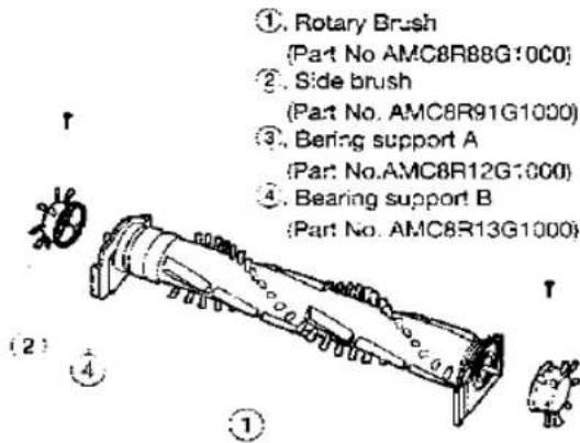
HOW TO REPLACE - ROTARY BRUSH / SIDE BRUSHES / BEARING SUPPORT A-B
- First remove the base plate, drive belt and lift out the rotary brush assembly (as illustrated above).
- Remove the 2 screws at both ends of the rotary brush assembly and separate the different parts as shown in the exploded view.
- Replace any damaged part and reassemble in reverse order.
HOW TO REPLACE HEAD-LIGHT BULB (MC-E457UK only) (Part No. AMC8D25B6100)
- Remove the base plate, release the head-light assembly and lift it up. (Fig.1)
- Remove the old bulb simply pulling forward, and replace with a new one. (Consult your local dealer/ Service agent for a suitable replacement bulb).
- Re-insert the head-light assembly back into place, replace the base plate and re-fasten the screws securely.
(3)
2

natural_image
Technical line drawing of a mechanical assembly or assembly (no visible text or symbols)
natural_image
Illustration of a hand holding a small house next to a computer monitor (no text or symbols visible)REMINDER FOR CUSTOMER
The model and serial number of this product may be found on the name plate located at the back of your cleaner. You should note the model and serial number in the spaces provided and retain this book as a permanent record of your purchase.
Model Number:
Serial Number:
Date Purchased:
Where Purchased:
Panasonic España, S.A.
DIVISION DE ASPIRADORAS
Zona Industrial del Polígono de CELRA
17460 CELRÀ (Girona) SPAIN
- Operating Instructions
- Panasonic
- CAUTION FOR AC MAINS LEAD
- FOR YOUR SAFETY PLEASE READ THE FOLLOWING TEXT CAREFULLY
- How to replace the Fuse:
- IMPORTANT SAFETY INSTRUCTIONS FOR THE USER
- When using this vacuum cleaner, please observe these basic precautions. WARNING: To reduce the risk of fire, electric shock, or injury:
- CAUTIONS
- IDENTIFICATION OF MAIN PARTS
- HOW TO ASSEMBLE / OPERATE YOUR CLEANER
- D) VARIABLE POWER CONTROL (MC-E456UK, MC-E457UK Only)
- E) HANDLE ADJUSTMENT BY FOOT PEDAL
- E) BEATER BAR SWITCH
- G) HOW TO USE THE ACCESSORIES
- H) DUST BAG CHECK INDICATOR
- CAUTION: DISCONNECT THE CLEANER FROM THE MAINS OUTLET BEFORE THE OPERATIONS BELOW
- 1) HOW TO CHANGE THE DUST BAG
- -1) FILTER CARE
- Central Filter (Fig. 1)
- Clean Air Filter (Fig. 2)
- TROUBLE SHOOTING GUIDE
- IMPORTANT NOTE: Before servicing any part always,
- DISCONNECT THE CLEANER FROM THE ELECTRICITY
- BLOCKAGES
- MAINTENANCE FOR THE ROTARY BRUSH
- SERVICING AND REPAIRS
- HOW TO REPLACE - DRIVE BELT TYPE UB-1L / ROTARY BRUSH ASSEMBLY (Part No. AMC8R98G1000)
- HOW TO REPLACE - ROTARY BRUSH / SIDE BRUSHES / BEARING SUPPORT A-B
- HOW TO REPLACE HEAD-LIGHT BULB (MC-E457UK only) (Part No. AMC8D25B6100)
- REMINDER FOR CUSTOMER
Marke : PANASONIC
Modell : MC-E455
Kategorie : Staubsauger