FNC-0104FX - Netzwerkkarte / Adapter LEVELONE - Kostenlose Bedienungsanleitung
Finden Sie kostenlos die Bedienungsanleitung des Geräts FNC-0104FX LEVELONE als PDF.

| Produkttyp | Netzwerkkarte / Adapter |
| Modell | FNC-0104FX |
| Marke | LevelOne |
| Schnittstelle | PCI (32-Bit, Bus-Mastering) |
| Datenübertragungsrate | 100 Mbit/s (Fast Ethernet) |
| Anschlusstyp | SC Duplex (Glasfaser) |
| Übertragungsmedium | Multimode-Faser 62,5/125 µm |
| Wellenlänge | 1300 nm |
| Maximale Kabellänge | 2 km (Halbduplex), 412 m (Vollduplex) |
| Netzstandard | IEEE 802.3u 100Base-FX |
| Unterstützte Betriebssysteme | Windows 98/ME/2000/XP; Linux; Novell NetWare |
| LED-Anzeigen | Link/Activity, Full-Duplex/Collision |
| Abmessungen (B x H x T) | 120 x 80 x 20 mm |
| Gewicht | ca. 50 g |
| Stromversorgung | Über PCI-Bus (3,3 V / 5 V) |
| Stromverbrauch | ca. 2,5 W |
| Betriebstemperatur | 0 °C bis 50 °C |
| Lagertemperatur | -20 °C bis 70 °C |
| Luftfeuchtigkeit (Betrieb) | 10 % bis 90 % (nicht kondensierend) |
| Reinigung | Mit trockenem, fusselfreiem Tuch reinigen; keine Flüssigkeiten verwenden |
| Sicherheitshinweise | Nur in trockener Umgebung verwenden; vor Feuchtigkeit schützen; keine eigenständigen Reparaturen durchführen |
| Ersatzteile / Reparatur | Keine vom Benutzer reparierbaren Teile; bei Defekt Fachmann kontaktieren |
Häufig gestellte Fragen - FNC-0104FX LEVELONE
Benutzerfragen zu FNC-0104FX LEVELONE
0 Frage zu diesem Gerät. Beantworten Sie die, die Sie kennen, oder stellen Sie Ihre eigene.
Eine neue Frage zu diesem Gerät stellen
Laden Sie die Anleitung für Ihr Netzwerkkarte / Adapter kostenlos im PDF-Format! Finden Sie Ihr Handbuch FNC-0104FX - LEVELONE und nehmen Sie Ihr elektronisches Gerät wieder in die Hand. Auf dieser Seite sind alle Dokumente veröffentlicht, die für die Verwendung Ihres Geräts notwendig sind. FNC-0104FX von der Marke LEVELONE.
BEDIENUNGSANLEITUNG FNC-0104FX LEVELONE
FNC-0103/0104FX
Fast Ethernet 100Base-FX
User's Manual
(9802-Rev. D1)
1. Checklist
Before you start installing the FNC-0103/0104FX, verify that the package contains the following items:
FNC-0103/0104FX Board
□ LAN Driver Diskette
This User's Manual
Please notify your sales representative immediately if any of the aforementioned items is missing or damaged.
2. Overview
FNC-0103/0104FX is a PCI Fast Ethernet Board that fully complices with all IEEE 802.3u, 100Base-FX standards. Four LED indicators(LINK, ACT, COL and FDX) on the bracket will help to oversee the network/board link, activities, collision and full-duplex status.
3. FNC-0103/0104FX PCI Configuration
For motherboards with automatic PCI configuration:
☐ No specific setup is needed
You can enter the system BIOS setup menu to view or specify the interrupt line of the PCI slots
For motherboards with bus master & interrupt jumpers:
■ Enable bus master operation in a selected PCI slot and select an interrupt (IRQ) level using the appropriate motherboard jumper
■ Enable I/O on the FNC-0103/0104FX PCI slot
4. PCI Bus System & Configuration
- Ensure that the PCI machine docs support master slots, INT multiple sharing and timing compatibility. Do not install FNC-0103/0104FX in PCI slave slots. Please refer
to your PCI system manual and select the appropriate configuration settings.
1
- When installing multiple FNC-0103/0104FX boards at the server station, you should correctly configure the IRQ settings of the PCI slot. Up to four FNC-0103/0104FX boards can be installed in a PCI file server running NetWare system. The FNC-0103/0104FX server boards share the same interrupt line with the driver supporting multiple INT services at a time. Each FNC-0103/0104FX's IRQ should not conflict with that of other board.
• Operation in full or half-duplex(Default) mode is
configured by LAN driver options. The operating mode should match the remote link device working status.
- You must use EMM386 version 4.49 or higher, and install both DOS & EMM386 that came from the same DOS package to avoid software problems.
5. Network Connection
100Base-FX/TX network allows 512-bit time delay between any two node stations in a collision domain. The Fiber/TP cable with devices' bit-time delay(round trip) are as below:
100Base-FX 100Base-TX
| DTE←DTE: 100Class II Hub: 92 Class II Hub : 92Fiber Cable : 1.0/m | DTE←DTE : 100Cat. 5 TP Wire: 1.112/m |
DTE FX to DTE TX: 100
0Base-FX to 100Base-TX Converter: 56
The overall bit-time of Fiber/TP wires and devices must be within 512 bit in a segment. You may use Switching Hub to break up collision domain and extend the cabling distance.
• Fiber Cable(multi-modc) Limitations:
| Half-duplex Class II Hub | Node to Node | : 205m |
| Node to Hub : | 100m | |
| Hub to Hub : | 5m | |
| Half-duplex Switching Hub | Node to Node | : 412m |
| Node to Hub : | 412m | |
| Hub to Hub : | 412m | |
| Full-duplex Switching Hub | Node to Node | : 2km |
| Node to Hub : | 2km | |
| Hub to Hub : | 2km |
Connecting to Router, Bridge, or Switching Hub, please refer to the device Technical Manual.
2
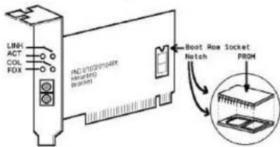
6. Diagnostic LEDs & Boot ROM
The Link LED lights when fiber cable connection is good and the Act LED blinks to indicate the activity. Collision and full-duplex LED report the board operating status.
To add the Remote Boot feature to a workstation, insert the Boot ROM into socket as shown below. Align the notch and pins on the Boot ROM with the notch and pin receptacles on the ROM socket. Gently push the Boot ROM into the socket, being careful not to bend the pins.
Fig. 1 Diagnostic LEDs and Boot ROM Socket
7. Technical Specifications
• Standard : IEEE 802.3u Fast Ethernet 100Base-FX
- Connector:
FNC-0103FX: ST(multi-mode) connector
FNC-0104FX: SC(multi-mode) connector
- Cable:
Fiber 50/125, 62.5/125, 100/140×m multi-mode
• Data Transfer Mode / Speed:
PCI bus master
Full or half-duplex(Default) mode
100Mbps speed
• LINK, ACT, COL, and FDX LEDs on the bracket
• Power Requirement : 2.0A @+5V
• Ambient Temperature : 0 to 50°C
• Humidity : 5% to 90%
• PCB Dimensions : 4.84"(L) - 3.15"(H)
• Complies with FCC Part 15 Class A and CE Mark