
ICA-PM 102XL - Wandhalterung für Flachbildschirme Techly - Kostenlose Bedienungsanleitung
Finden Sie kostenlos die Bedienungsanleitung des Geräts ICA-PM 102XL Techly als PDF.


| Produkttyp | Wandhalterung für Flachbildschirme |
| Marke | Techly |
| Modell | ICA-PM 102XL |
| Kompatible Bildschirmgröße | 26–42 Zoll (66–107 cm) |
| VESA-Norm | VESA 75x75, 100x100, 200x100, 200x200 |
| Maximale Tragfähigkeit | 30 kg |
| Material | Stahl (kaltgewalzt), pulverbeschichtet |
| Farbe | Schwarz |
| Abstand zur Wand | 60 mm |
| Neigung (Tilt) | −5° bis +15° |
| Schwenkung (Swivel) | ±180° |
| Nivellierung (Rotation) | ±3° |
| Installation | Wandmontage, inkl. Montageset und Schablone |
| Gewicht (Halterung) | 1,5 kg |
| Abmessungen (B×H×T) | 480×125×60 mm |
| Garantie | 2 Jahre |
| Reinigung | Feuchtes Tuch, kein aggressives Reinigungsmittel |
| Sicherheit | Entspricht Sicherheitsnormen; für Innenräume mit ausreichender Wandverankerung |
| Lieferumfang | Halterung, Schrauben, Dübel, Wandschablone, Anleitung |
Häufig gestellte Fragen - ICA-PM 102XL Techly
Benutzerfragen zu ICA-PM 102XL Techly
0 Frage zu diesem Gerät. Beantworten Sie die, die Sie kennen, oder stellen Sie Ihre eigene.
Eine neue Frage zu diesem Gerät stellen
Laden Sie die Anleitung für Ihr Wandhalterung für Flachbildschirme kostenlos im PDF-Format! Finden Sie Ihr Handbuch ICA-PM 102XL - Techly und nehmen Sie Ihr elektronisches Gerät wieder in die Hand. Auf dieser Seite sind alle Dokumente veröffentlicht, die für die Verwendung Ihres Geräts notwendig sind. ICA-PM 102XL von der Marke Techly.
BEDIENUNGSANLEITUNG ICA-PM 102XL Techly
Tlly TECHly®
Universal Projector Ceiling Mount
Istruzioni installazione Installation Instruction
ICA-PM 102

natural_image
Black mechanical component with three arms and a green horizontal bar (no text or symbols visible)Gentile Cliente,
grazie per aver scelto un prodotto Techly.
Istruzioni disimballaggio
- Aprire il cartone con cura, rimuovere il contenuto e distenderlo su un cartone o altro materiale protettivo per evitare danni;
- Verificare che il contenuto della confezione corrisponda alla lista delle parti nella pagina successiva per assicurarsi che tutti i componenti siano presenti e non siano danneggiati. Non utilizzare parti difettose o danneggiate;
- Leggere attentamente le istruzioni riportate nel presente manuale prima di procedere all'installazione;
- Tenere sempre questo manuale per future consultazioni.
Importanti informazioni sulla sicurezza
Installare e utilizzare questo prodotto con cura.
Leggere cortesemente le istruzioni prima di cominciare l'installazione e seguire scrupolosamente tutte le indicazioni contenute qui. Utilizzare adeguati dispositivi di sicurezza durante l'intallazione.
Contattare del personale qualificato per effettuare l'installazione:
- Se non avete compreso le indicazioni conte questo manuale o avete dei dubbi in merito alla sicurezza dell'installazione;
- Se non siete sicuri circa la tipologia del muro dove effettuare l'installazione del supporto;
Non utilizzate il prodotto per uno scopo o in una configurazione non espressamente specificata in istruzioni. Si declina qualsiasi responsabilità per danni derivanti da un errato assemblaggio, errato montaggio o uso non corretto del prodotto.
Al termine delle operazioni di montaggio assicurarsi che il tutto sia stato effettuato a regola d'arte.
Dear Customer,
thanks for choosing a Techly product. Enjoy the using.
Unpacking Instructions
- Carefully open the carton, remove contents and lay out on cardboard or other protective surface to avoid damage.
- Check package contents against the Supplied Parts List in the next page to assure that all components were received undamaged. Do not use damaged or defective parts.
- Carefully read all instructions before attempting installation.
- Keep this user's manual for next consultation
Important Safety Information
Install and operate this device with care.
Please read this instruction before beginning the installation, and carefully follow all instructions contained herein. Use proper safety equipment during installation.
Please call a qualified installation contractor for help if you:
If you don't understand these directions or have any doubts about the safety of the installation.
- If you are uncertain about the nature of your wall, consult a qualified installation contractor.
Do not use this product for any purpose or in any configuration not explicitly specified in this instruction.
d) whereby disclaims any and all liability for injury or damage arising from incorrect assembly, incorrect mounting, or incorrect use of this product.
At the end of the fixing care that the support is installed in the correct way

ATTENZIONE: Questa staffa per proiettore deve essere fissata al soffitto in modo sicuro.
Se il montaggio non è stato effettuato modo corretto e stabile, ciò potrebbe causare la caduta della staffa, determinando lesioni o danni a cose e persone
CAUTION: This projector mount must be securely attached to the ceiling. If the mount is not properly installed it may fall, resulting in possible injury and/or damage.
ATTREZZATURA RICHIESTA:
Punta del trapano da 3.8 mm - Cacciavite Philips - Punta da muro da 8 mm
Nota: i componenti e il materiale di fissaggio questa confezione non sono indicati per le installazioni su soffitti con intelaiatura in acciaio. Assicurarsi dell'integrità del muro prima di procedere all'installazione. tassativamente il peso massimo dell'apparecchiatur supportata indicato nella confezione. Se il mat fissaggio di cui avete bisogno non è incluso
la vostra ferramenta locale per individuare il materiale di montaggio indicato per la vostra applicazione. Il produttore non si assume alcuna responsabilità in caso di ancoraggio non corretto.
TOOLS REQUIRED:
3.8mm Drill Bit - Phillips Screwdriver - 8mm Masonry Bit
Note: The mounting components and hardware supplied in this package are not designed for installations to ceiling with steel studs. If the hardware you need for your installation is not included, please consult your local hardware store Rifpretraper mounting hardware for the application. Please rapay careful attention to where this mount is located, some terminals and not suitable for installation. Respect the maximum p, weight utilitation printed on the box.
-
LISTA DELLE PARTI FORNITE | SUPPLIED PARTS LIST
natural_image
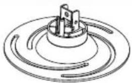
Technical line drawing of a mechanical component with concentric circular grooves and central shaft (no text or symbols)(1) Placca proiettore-a
(1) Projector Plate-a

(1) Placca per soffitto-b
(1) Ceiling Plate-b
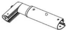
(1) Set tubi-c
(1) Tube Set-c
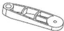
(4) Piedini di montaggio-d
(4) Mounting Legs-d
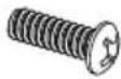
(4) M3x16 viti-e
(4) M3x16 Bolt-e
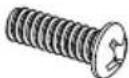
(4) M4x12 viti-f
(4) M4x12 Bolt-f
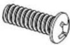
(4) M5x12 viti-g
(4) M5x12 Bolt-g

(4) M6x12 viti-h
(4) M6x12 Bolt-h

(4) M3/M4 rondelle-i
(4) M3/M4 Washer-i

(8) M6x16 viti a brugola-j
(8) M6x16 Hexangular Head Bold-j

(1) Chiave a brugola-k
(1) Allen Wrench-k

(3) Viti per tasselli-I
(3) Lag Bolt-I

(3) Tasselli-m
(3) Concrete Anchor-m

(4) M3x10 viti-n
(4) M3x10 Bolt-n
Selezionare gli elementi di fissaggio adeguati
-
Capovolgete il proiettore e individuate i punti di fissaggio.
-
Testate ciascuna misura di vite fornita 2.
-
Le viti corrette dovrebbero infilarsi facilmente nei punti di fissaggio e non dovrebbero uscire se viene loro applicata una pressione.
Selecting the Proper Mounting Hardware
Invert the projector and locate the mounting points Test each size of the screws provided
The correct screws should thread easily into the mounting point and not pull out when pressure is applied.

NON STRINGETE TROPPO LE VITI DI FISSAGGIO AL TELAIO DEL PROIETTORE. L'USO DI VITERIA CON LUNGHEZZA NON CORRETTA POTREBBE DANNEGGIARE IL VOSTO PROIETTORE.
DO NOT OVER-TIGHTEN YOUR MOUNTING SCREWS TO THE PROJECTOR CHASSIS.
STOP USING THE INCORRECT SCREW DEPTH MAY CAUSE DAMAGE TO YOUR PROJECTOR.

ATTENZIONE: È possibile stringere
questo dado per aumentare zione del vostro proiettore. Ma semente non stringetelo troppo forte o potreste avere problemi con il sistema di inclinazione.

nut
dado
ATTEnTlon: You can tighten this nut if you want to make the big tilting for your projector. But please don't over-tighen, otherwise you may have problem to do the tilting.
STEP 1
Installazione dei piedini di montaggio sul proiettore Install the Mounting Legs on the Projector
- Individuate i punti di montaggio sulla parte inferiore del proiettore.
- Attaccate il numero adeguato di piedini di montaggio (d) al proiettore usando le viti di fissaggio adeguate (e, f, g, h, n).
- Non stringere completamente queste viti per il momento.
- Le rondelle M3/M4 (i) devono essere utilizzate se usate viti M3/M4.
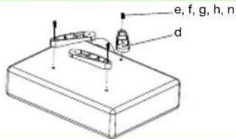
- Locate the mounting points on the bottom of the projector.
- Attach the appropriate number of Mounting Legs(d) to the projector using the appropriate mounting Bolts(e,f,g,h,n).
- Do not tighten these bolts completely at this time.
- The M3/M4 Washers(i) have to be used if you use the M3/M4 bolts.
STEP 2
Installazione della placca del proiettore ai piedini di montaggio Install the Projector Plate to the Mounting Legs
- Allineare la placca del proiettore (a) ai piedini di montaggio.
- Posizionare i piedini per ottenere la migliore configurazione. Potete alzare o abbassare ciascun indipendentemente.
- Assicurate i piedini alla placca del proiettore tramite le viti a brugola M6x16 (j) (non stringere troppo) usando la chiave a brugola (k) fornita in dotazione.
- Stringete tutte le viti in questo momento.

- Align the Projector Plate(a) to the mounting legs.
- Position the legs accordingly for best configuration. You may raise or lower each leg independently.
- Secure the legs to the projector plate by screwing M6x16 Hexangular Head Bolt(j) (do not over-tighten) on the mounting legs, using the Allen Wrench(k) provided.
- Tighten all bolts at this time.
STEP 3
Installazione della placca a soffitto sul soffitto | Install the Ceiling Plate to the Ceiling
Utilizzate la placca da soffitto (b) come sagoma per segnare le posizioni dei 3 fori da effettuare sul soffitto. Praticare i fori con una trapano da 8 mm e fate in modo che i fori abbiano una profondità di almeno 50mm. Inserire un tassello (m) in ciasuno di questi fori. Assicuratevi che i tasselli siano inseriti completamente e siano a filo con la superficie in calcestruzzo, anche se, frontalmente, vi è uno strato di cartongesso o di altro materiale. Fissate la placca al soffitto utilizzando le 3 viti per i tasselli (l) e i 3 tasselli (m).
soffitto in cemento
punta concrete ceiling
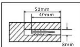

Use the Wall Plate(b) as a template to mark 3 hole locations on the wall. Pre-Drill these holes with a 8mm masonry bit to at least 50mm in depth. Insert a Concrete Anchor(m) into each of these holes. Make sure the anchor is seated completely flush with the concrete surface even if there is a layer of drywall or other material in front.
Attach the wall plate to the wall using 3 pieces Lag Bolts(I) and 3 pieces Concrete Anchor(m).
Utilizzato l'apposito strumento per individuare assi dell'intelaiatura. Potrebbe essere una buona idea verificare dove le assi sono posizionate con
un punteruolo o con chiodo sottile come mostrato nello schema. Praticate un foro di 50mm di pro- fondità in ciasuna asse utilizzando una punta da
3.8mm. Assicuratevi che i fori siano nella parte centrale delle assi. Utilizzate la placca a soffitto come sagoma per segnare la posizione dei del secondo foro sull'asse. Praticate un foro da 50mm di profondità, utilizzando una punta da 3.8 mm nella seconda posizione segnata. placca al soffitto utilizzando le 2 viti per i tasselli (I)
^le soffitto con intelaiatura con assi in legno wood stud ceiling
posizionati
Fissate


Use a stud finder to locate the stud. It is a good idea to verify where the stud is located with an awl or thin nail. Pre-drill a 50mm deep hole at the stud using a 3.8mm drill bit. Make sure the hole is in the center area of the stud. Use the Wall Plate(b) as a template to mark the location of the second hole in the stud. Drill 50mm deep hole using the 3.8mm drill bit in the marked location. Attach the wall plate to the wall using the 2 pieces Lag Bolts(l).
STEP 4
Collegare il set di tubi alla placca a soffitto | Connecting Tube Set to Ceiling Plate
Collegare il set di tubi (c) e la placca a soffitto (b) tramite 2 viti a brugola M6x16 (j) come nella figura, stringendole con la chiave a brugola (K) fornita.

Connecting the Tube Set(c) and Ceiling Plate(b) by 2 pieces M6x16 Hexangular Head Bolts(j) as the picture, tighten by Allen Wrench(k) provided.
STEP 5
Collegare il set di tubi alla placca del proiettore | Connecting the Tube Set to Projector Plate
Collegare il set di tubi (c) e la placca del proiettore (a) tramite 2 viti a brugola M6x16 (j) come nella figura, e stringerle tramite la chiave a brugola fornita (k).

Connecting the Tube Set(c) and Projector Plate(a) by 2 pieces M6x16 Hexangular Head Bolts(j) as the picture, tighten by Allen Wrench(k) provided.


- Tlly TECHly®
- Universal Projector Ceiling Mount
- Gentile Cliente,
- Istruzioni disimballaggio
- Importanti informazioni sulla sicurezza
- Dear Customer,
- Unpacking Instructions
- Important Safety Information
- ATTREZZATURA RICHIESTA:
- TOOLS REQUIRED:
- LISTA DELLE PARTI FORNITE | SUPPLIED PARTS LIST
- Selezionare gli elementi di fissaggio adeguati
- Selecting the Proper Mounting Hardware
- STEP 1
- Installazione dei piedini di montaggio sul proiettore Install the Mounting Legs on the Projector
- STEP 2
- Installazione della placca del proiettore ai piedini di montaggio Install the Projector Plate to the Mounting Legs
- STEP 3
- Installazione della placca a soffitto sul soffitto | Install the Ceiling Plate to the Ceiling
- STEP 4
- Collegare il set di tubi alla placca a soffitto | Connecting Tube Set to Ceiling Plate
- STEP 5
- Collegare il set di tubi alla placca del proiettore | Connecting the Tube Set to Projector Plate
Marke : Techly
Modell : ICA-PM 102XL
Kategorie : Wandhalterung für Flachbildschirme