
FTXM60M - Aircondition DAIKIN - Gratis brugsanvisning og manual
Find enhedens vejledning gratis FTXM60M DAIKIN i PDF-format.

Brugerspørgsmål om FTXM60M DAIKIN
0 spørgsmål om dette apparat. Besvar dem du kender, eller stil dit eget.
Stil et nyt spørgsmål om dette apparat
Download vejledningen til din Aircondition i PDF-format gratis! Find din vejledning FTXM60M - DAIKIN og tag din elektroniske enhed tilbage i hånden. På denne side er alle dokumenter nødvendige for brugen af din enhed offentliggjort. FTXM60M af mærket DAIKIN.
BRUGSANVISNING FTXM60M DAIKIN
Air Conditioning
Technical Data
RXM-M
natural_image
Exterior view of a DAIKIN air conditioning unit with grid fan and R32 branding (no readable text beyond branding)TABLE OF CONTENTS
RXM-M
1 Features 2
2 Specifications 3
Capacity and Power input 3
Technical Specifications 4
Electrical Specifications 6
3 Electrical data....7
4 Capacity tables 10
Cooling/Heating Capacity Tables 10
5 Dimensional drawings 17
6 Centre of gravity 19
7 Piping diagrams 23
8 Wiring diagrams 25
Wiring Diagrams - Single Phase 25
9 Sound data 27
Sound Pressure Spectrum 27
10 Operation range 31
1 Features
• Seasonal efficiency values up to A+++
• Anti-corrosion treated outdoor heat exchanger fin
- Daikin outdoor units are neat, sturdy and can easily be mounted on a roof or terrace or simply placed against an outside wall
- Outdoor units are fitted with a swing compressor, renowned for its low noise and high energy efficiency
• Outdoor units for pair application
1
natural_image
Exterior view of a DAIKIN air conditioning unit with fan grille and R32 branding (no readable text beyond branding)
Outdoor unit
silent operation
2 Specifications
| 2-1 Capacity and Power input | FTXM20M/RXM20M | FTXM25M/RXM25M | FTXM35M/RXM35M | FTXM42M/RXM42M | FTXM71M/RXM71M | FTXM50M/RXM50M | FTXM60M/RXM60M | ||||
| Indoor unit FTXM20M FTXM25M FTXM35M FTXM42M FTXM71M FTXM50M | FTXM60M | ||||||||||
| Outdoor unit RXM20M RXM25M RXM35M RXM42M RXM71M RXM50M RXM60M | FTXM60M | ||||||||||
| Cooling capacity Rated kW - 7.10 - | |||||||||||
| Btu/h - 24 | 200.00 | - | |||||||||
| kcal/h | - | 6,100.00 | - | ||||||||
| Min. | kW | 1.3 | 1.4 | 1.7 | 2.3 | 1.7 | |||||
| Btu/h | 4,400 | 4,800 | 5,800 | 7,800.0 | 5,800 | ||||||
| kcal/h | 1,120 | 1,200 | 1,460 | 2,000.0 | 1,460 | ||||||
| Nom. | kW | 2.0 | 2.5 | 3.40 | 4.2 | 7.10 | 5.00 | ||||
| Btu/h | 6,800 | 8,500 | 11,600 | 14,300 | 24,200.0 | 17,100 | |||||
| kcal/h | 1,720 | 2,150 | 2,920 | 3,610 | 6,100.0 | 4,300 | |||||
| Max. | kW | 2.6 | 3.2 | 4.0 | 5.0 | 8.5 | 5.3 | ||||
| Btu/h | 8,900 | 11,000 | 13,600 | 17,100 | 29,000.0 | 18,100 | |||||
| kcal/h | 2,240 | 2,750 | 3,440 | 4,300 | 7,300.0 | 4,560 | |||||
| Heating capacity | Rated kW - 8.20 - | ||||||||||
| Btu/h - 28 | 000.00 | - | |||||||||
| kcal/h | - | 7,000.00 | - | ||||||||
| Min. | kW | 1.3 | 1.4 | 1.7 | 2.30 | 1.7 | |||||
| Btu/h | 4,400 | 4,800 | 5,800 | 7,800.0 | 5,800 | ||||||
| kcal/h | 1,120 | 1,200 | 1,460 | 2,000.0 | 1,460 | 1,500 | |||||
| Nom. | kW | 2.50 | 2.8 | 4.00 | 5.40 | 8.20 | 5.8 | 7.00 | |||
| Btu/h | 8,500 | 9,500 | 13,600 | 18,400 | 28,000.0 | 19,800 | 23,900 | ||||
| kcal/h | 2,150 | 2,400 | 3,440 | 4,640 | 7,000.0 | 4,990 | 6,020 | ||||
| Max. | kW | 3.5 | 4.70 | 5.2 | 6.0 | 10.20 | 6.5 | 8.0 | |||
| Btu/h | 11,900 | 16,000 | 17,700 | 20,500 | 34,800.0 | 22,200 | 27,300 | ||||
| kcal/h | 3,010 | 4,040 | 4,470 | 5,160 | 8,800.0 | 5,590 | 6,900 | ||||
| Power input | Cooling | Min. | kW | 0.27 | 0.31 | 0.43 | 0.49 | - | 0.30 | ||
| Nom. | kW | 0.44 | 0.56 | 0.80 | 1.12 | 2.12 | 1.36 | 1.77 | |||
| Max. | kW | 0.63 | 0.78 | 1.04 | 1.47 | 3.44 | - | 2.30 | |||
| Heating | Min. | kW | 0.24 | 0.32 | 0.38 | 0.45 | - | 0.27 | |||
| Nom. | kW | 0.50 | 0.56 | 0.99 | 1.31 | 2.25 | 1.45 | 1.94 | |||
| Max. | kW | 0.91 | 1.22 | 1.67 | 1.89 | 3.51 | - | 2.40 | |||
| Seasonal efficiency (according to EN14825) | Cooling | Energy label | A+++ | A++ | |||||||
| Pdesign | kW | 2.00 | 2.50 | 3.40 | 4.20 | 7.10 | 5.00 | 6.00 | |||
| SEER | 8.53 | 8.52 | 8.51 | 7.50 | 6.11 | 7.33 | 6.90 | ||||
| Annual energy consumption | kWh | 83 | 103 | 140 | 196 | 407 | 239 | 304 | |||
| Heating (Average climate) | Energy label | A+++ | A++ | A | A++ | A+ | |||||
| Pdesign | kW | 2.30 | 2.40 | 2.50 | 4.00 | 6.20 | 4.60 | ||||
| SCOP/A | 5.10 | 4.60 | 3.81 | 4.60 | 4.30 | ||||||
| Annual energy consumption | kWh | 632 | 659 | 686 | 1,216 | 2,276 | 1,400 | 1,496 | |||
| Piping connections | Liquid | Quantity | - | 1 | - | ||||||
| Gas | Quantity | - | 1 | - | |||||||
| Current - 50Hz | Maximum running current | A | - | 18.3 | - | ||||||
| Current | Nominal running current (RLA) - 50Hz | Cooling | A | 2.09 | 2.57 | 4.38 | 5.11 | 7.2 | 6.26 | 7.90 | |
| Heating | A | 2.23 | 2.48 | 4.78 | 5.93 | 7.2 | 6.56 | 8.50 | |||
| Eurovent | Sound power level outdoor | Cooling | Nom. | dBA | 59 | 61 | 62 | 66 | 62 | 63 | |
| Sound power level indoor | Cooling | Nom. | dBA | 57 | 60 | 62 | 59 | 60 | |||
| Piping length | Cooling | Measuring condition | m | - | 5.0 | - | |||||
2 Specifications
| 2-1 Capacity and Power input | FTXM20M/RXM20M | FTXM25M/RXM25M | FTXM35M/RXM35M | FTXM42M/RXM42M | FTXM71M/RXM71M | FTXM50M/RXM50M | FTXM60M/RXM60M | ||
| Nominal efficiency EER | 4.57 4.50 4.23 3.75 3.35 3.68 3.39 | ||||||||
| COP 5.00 4.40 4.12 3.65 4.00 3.61 | |||||||||
| Annual energy consumption kWh 219 278 | 421 560 1 | 172 679 885 | |||||||
| Energy label Cooling | A B A | ||||||||
| Heating | A | - | A | ||||||
Notes
EER/COP according to Eurovent 2012, for use outside EU only
Nominal efficiency: cooling at 35°/27° nominal load, heating at 7°/20° nominal load
| 2-2 Technical Specifications | RXM20M | RXM25M | RXM35M | RXM42M | RXM50M | RXM60M | RXM71M | ||||
| Capacity control | Method | - | Variable (inverter) | ||||||||
| Casing | Colour | Ivory white | |||||||||
| Dimensions | Unit | Height | mm | 550 | 735 | 734 | |||||
| Width | mm | 765 | 825 | 870 | |||||||
| Depth | mm | 285 | 300 | 320 | |||||||
| Packed unit | Height | mm | 612 | 797 | 820 | ||||||
| Width | mm | 906 | 992 | 1,050 | |||||||
| Depth | mm | 402 | 437 | 480 | |||||||
| Weight | Unit | kg | 32 | 47 | 44 | 56.0 | |||||
| Packed unit | kg | 34 | 48 | 60 | |||||||
| Packing | Material | - | PE wrapping foil / EPS / Carton / PP (Straps) | ||||||||
| Weight kg 2 | 1 | 4 | |||||||||
| Heat exchanger | Length | mm | 805 | 845 | 920 | ||||||
| Rows | Quantity | 2 | |||||||||
| Fin pitch | mm | 1.4 | 1.8 | 1.40 | |||||||
| Face area | m2 | - | 0.658 | ||||||||
| Stages | Quantity | 24 | 32 | ||||||||
| Tube type | ø7 Hi-XD | ø8 Hi-XA | 7.0 Hi-XD | ||||||||
| Tube material | - | Seamless copper | |||||||||
| Tube diameter | mm | - | 7 | ||||||||
| Fin | Type | Waffle fin (PE) | Precoat Fin | Waffle fin (PE) | |||||||
| Treatment | - | Anti Corrosion Hydrophilic | |||||||||
| Compressor | Quantity | - | 1 | ||||||||
| Model | 1YC25GXD#C | 2YC40JXD C | 2YC40GXD #A | 2YC40JXD C | 2YC71DXD #C | ||||||
| Oil Amount | cm3 | - | 900 | ||||||||
| Type | Hermetically sealed swing compressor | ||||||||||
| Output | W | 800 | 1,300 | 1,300.0 | 2,400.0 | ||||||
| Power input | Cooling | Nom. | W | - | 2,065 | ||||||
| Heating | Nom. | W | - | 2,187 | |||||||
| Running current | Cooling | Nom. | A | - | 9 | ||||||
| Heating | Nom. | A | - | 10 | |||||||
2 Specifications
| 2-2 Technical Specifications | RXM20M | RXM25M | RXM35M | RXM42M | RXM50M | RXM60M | RXM71M | ||||
| Fan Type Propeller fan | Propeller | ||||||||||
| Discharge direction - Horizontal | |||||||||||
| Quantity - | 1 | ||||||||||
| Air flow rate Cooling | High m3/m | In 36.0 50 | 9 50.4 67.3 | ||||||||
| cfm | 1,271 | 1,800 | 1,780 | 2,380 | |||||||
| Low | m3/min | - | 38.5 | - | |||||||
| cfm | - | 1,359 | - | ||||||||
| Heating | High m3/min | 28.3 45 | 4 40.4 55.3 | ||||||||
| cfm | 999 | 1,603 | 1,427 | 1,950 | |||||||
| Low | m3/min | - | 34.3 | 40.4 | - | ||||||
| cfm | - | 1,211 | 1,427 - | ||||||||
| Running current | Cooling | Standard | A | - | 0.4 | ||||||
| Heating | Standard | A | - | 0.4 | |||||||
| Fan motor | Quantity - | 1 | |||||||||
| Model | ARW34W8P50DA | KFD-380-50-8D | ARW7406DA | D90B-37 | |||||||
| Index of Protection | - | 23 | |||||||||
| Insulation grade | - | Class "E" | |||||||||
| Poles | - | 8 | |||||||||
| Output | W | 50 | 68 | 128 | |||||||
| Drive | - Brushless | ||||||||||
| Speed | Cooling | High | rpm | 920 | 780 | 710 | 810 | 880 | |||
| Nom. | rpm | - | 780 | ||||||||
| Low | rpm | 800 | 620 | 630 | 620 | 700 | |||||
| Super low | rpm | - | 680 | ||||||||
| Heating | High | rpm | 860 | 730 | 740 | ||||||
| Nom. | rpm | - | 740 | ||||||||
| Low | rpm | 400 | 730 | 620 | 730 | 680 | |||||
| Super low | rpm | - | |||||||||
| Sound power level | Cooling | dBA | 59 | 61 | 63 | 64 | |||||
| Heating | dBA | 59 | 61 | 63 | 62 | 63 | 64 | ||||
| Sound pressure level | Cooling | High | dBA | 46 | 49 | 48 | 47 | ||||
| Low | dBA | - | 44 - | ||||||||
| Heating | High | dBA | 47 | 49 | 48 | 49 | 48 | ||||
| Low | dBA | - | 45 - | ||||||||
| Operation range | Cooling | Ambient | Min. | °CDB | -10 | ||||||
| Max. | °CDB | 46 | |||||||||
| Heating | Ambient | Min. | °CWB | -15 | |||||||
| Max. | °CWB | 18 | |||||||||
| Refrigerant | Type | R-32 | |||||||||
| Charge | kg | 0.76 | 1.30 | 1.4 | 1.45 | 1.15 | |||||
| TCO2eq | 0.5 | 0.9 | 1.0 | 0.780 | |||||||
| Control | - | Inverter / Motor operated expansion valve | |||||||||
| GWP | 675 | ||||||||||
2 Specifications
| 2-2 Technical Specifications | RXM20M | RXM25M | RXM35M | RXM42M | RXM50M | RXM60M | RXM71M | ||||
| Piping connections Liquid Quantity - 1 | |||||||||||
| Type - Flare | connection | ||||||||||
| OD mm 6.35 | |||||||||||
| Gas Quantity - 1 | |||||||||||
| Type - Flare | connection | ||||||||||
| OD mm 9.5 12.7 15.9 | |||||||||||
| Drain | Quantity - 1 | ||||||||||
| ID | mm | - | |||||||||
| OD mm | 18 | ||||||||||
| Piping length | OU - IU | Min. | m | - | 3 | ||||||
| Max. | m | 15 | 30 | ||||||||
| System | Chargeless | m | 10 | ||||||||
| Additional refrigerant charge | kg/m | 0.02 (for piping length exceeding 10m) | |||||||||
| Level difference | IU - OU | Max. | m | 12 | 20 | ||||||
| Heat insulation | Both liquid and gas pipes | ||||||||||
| Refrigerant oil | Type | FW68DA | |||||||||
| Charged volume | I | 0.375 | 0.650 0.9 | ||||||||
| Defrost method | - | Reversedcycle | |||||||||
| Defrost control | - | Outdoorheatexchangerand ambientsensor | |||||||||
Standard Accessories : Drain plug (only heat pump models); Quantity : 1;
Standard Accessories : Installation manual; Quantity : 1;
Standard Accessories : Refrigerant charge label; Quantity : 1;
Standard Accessories : Multilingual fluorinated greenhouse gases labels; Quantity : 1;
Standard Accessories : Drain cap; Quantity : 6;
| 2-3 Electrical Specifications | RXM20M | RXM25M | RXM35M | RXM42M | RXM50M | RXM60M | RXM71M | |||
| Power supply | Name | V1 | ||||||||
| Phase | 1~ | |||||||||
| Frequency | Hz | 50 | ||||||||
| Voltage | V | 220-240 | ||||||||
| Voltage range | Min. | % | - | 90 | ||||||
| Max. | % | - | 110 | |||||||
| Current - 50Hz | Maximum fuse amps (MFA) | A | 10 | 15 | 20 | |||||
| Current | Nominal running current (RLA) | Cooling | A | 1.95 | 2.47 | 4.23 | 4.97 | 6.48 | 7.72 | 9.19 |
| Heating | A | 2.12 | 2.4 | 4.67 | 5.83 | 6.33 | 8.37 | 9.70 | ||
| Starting current | Cooling | A | 3.7 | 4.4 | 6.8 | 6.6 | 9.5 | |||
| Heating | A | 3.7 | 4.4 | 6.8 | 6.6 | 9.5 | ||||
| Maximum running current | Cooling | A | - | 17.7 | ||||||
| Heating | A | - | 17.7 | |||||||
| Current - 60Hz | Maximum fuse amps (MFA) | A | - | |||||||
Notes
SL: The silent fan level of the air flow rate setting
Contains fluorinated greenhouse gases
3 Electrical data
3 - 1 Electrical Data
RXM20-35M
| Unit combination restrictions | Power supply | COMP | OFM | IFM | ||||||||
| Indoor | Outdoor | 1 | 2 | 3 | M | C | A | M | F | A | R | |
| FTXM20M | RXM20M | 50 22050 23050 240 | MAX. 50Hz 264VMIN. 50Hz 198V | 8,0 | 10 | 35,0 | 2.20232.0 | 0,23 | 0,022 | 0,20 | ||
| FTXM25M | RXM25M | 50 22050 23050 240 | MAX. 50Hz 264VMIN. 50Hz 198V | 8,1 | 10 | 46,0 | 2.80232.6 | 0,23 | 0,022 | 0,20 | ||
| FTXM35M | RXM35M | 50 22050 23050 240 | MAX. 50Hz 264VMIN. 50Hz 198V | 8,8 | 10 | 60,0 | 4.60234.2 | 0,23 | 0,028 | 0,23 | ||
Z
Notes
1 The RLA is based on the following conditions.
Indoor temperature 27°C DB / 19°C WB
Outdoor temperature 35°C DB
2 Select the wire size according to the MCA.
^3 The maximum allowable voltage that is unbalanced between phases is 2%.
4 Use a circuit breaker instead of a fuse.
Symbols
1 Hz
^2 Voltage
3 Voltage range
MCA Minimum Circuit Ampere (A)
MFA Maximum Fuse Ampere (A)
RLA Rated load amps [A]
OFM Outdoor fan motor
IFM Indoor fan motor
FLA Full Load Ampere (A)
kW Fan motor rated output [kW]
RHz Rated operating frequency [Hz]
3D092132C
RXM42-50M
| Unit combination restrictions | Power supply | COMP | OFM | IFM | ||||||||
| Indoor | Outdoor | 1 | 2 | 3 | MCA | MFA | RHz | RLA | kW | FLA | kW | FLA |
| FTXM42M | RXM42M | 50 | 220 | MAX. 50Hz 264V | 9,3 | 10 | 56,5 | 5.2 | 0,068 | 0,34 | 0,023 | 0,15 |
| 50 | 230 | MIN. 50Hz 198V | 5.0 | |||||||||
| 50 | 240 | 4.8 | ||||||||||
| FTXM50M | RXM50M | 50 | 220 | MAX. 50Hz 264V | 14,0 | 15 | 53,5 | 4.9 | 0,068 | 0,34 | 0,023 | 0,15 |
| 50 | 230 | MIN. 50Hz 198V | 4.7 | |||||||||
| 50 | 240 | 4.5 | ||||||||||
Notes
- The RLA is based on the following conditions.
Indoor temperature 27°C DB / 19°C WB
Outdoor temperature 35°C DB
2 Select the wire size according to the MCA.
3 The maximum allowable voltage that is unbalanced between phases is 2%.
4 Use a circuit breaker instead of a fuse.
Symbols
1 Hz
7 Voltage
Voltage range
MCA Minimum Circuit Ampere (A)
MFA Maximum Fuse Ampere (A)
RLA Rated load amps [A]
OFM Outdoor fan motor
IFM Indoor fan motor
FIA Full Load Ampere (A)
kW Fan motor rated output [kW]
RHz Rated operating frequency [Hz]
3D092133A
3 Electrical data
3 - 1 Electrical Data
RXM42-60M
| Unit combination restrictions | Power supply | COMP | OFM | IFM | ||||||||
| Indoor | Outdoor | 1 | 2 | 3 | M | C | A | M | F | A | R | |
| FTXM42M2V1B | RXM42MV1B | 50 22050 23050 240 | MAX. 50Hz 264VMIN. 50Hz 198V | 9,3 | 10 | 56,5 | 5,20,684,8 | 0,34 | 0,028 | 0,23 | ||
| FTXM50M2V1B | RXM50MV1B | 50 22050 23050 240 | MAX. 50Hz 264VMIN. 50Hz 198V | 14,0 | 15 | 53,5 | 4,90,684,5 | 0,34 | 0,046 | 0,30 | ||
| FTXM60M2V1B | RXM60M2V1B | 50 22050 23050 240 | MAX. 50Hz 264VMIN. 50Hz 198V | 14,0 | 15 | 73,0 | 5,90,685,5 | 0,34 | 0,049 | 0,32 | ||
H
Notes
1 The RLA is based on the following conditions.
Indoor temperature 27°C DB / 19°C WB
Outdoor temperature 35°C DB
2 Select the wire size according to the MCA.
^3 The maximum allowable voltage that is unbalanced between phases is 2%.
4 Use a circuit breaker instead of a fuse.
Symbols
1 Hz
2 Voltage
3 Voltage range
MCA Minimum Circuit Ampere (A)
MFA Maximum Fuse Ampere (A)
OFM Outdoor fan motor
IFM Indoor fan motor
FLA Full Load Ampere (A)
kw Fan motor rated output [kW]
MHz Rated operating frequency [Hz]
RLA Rated load amps [A]
3D092133B
3 Electrical data
3 - 1 Electrical Data
FTXM71M2V1B - RXM71M2V1B
| Unit combination restrictions | Power supply | COMP | OFM | IFM | ||||||||
| Indoor unit | Outdoor unit | 1 | 2 | 3 | MCA M | IFA RHz | RLA kW | FLA | kW | FLA | ||
| FTXM71M2V1B RXM | 71M2V1B | 50 23 | 0 7,6 | MAX. 50Hz 264VMIN. 50Hz 198V | 18,3 20 | 49,0 0,05 | 58 0,38 | 0,052 | 0,34 | |||
| 50 23 | 0 7,2 | |||||||||||
| 50 24 | 0 6,9 | |||||||||||
Notes
- The RLA is based on the following conditions.
Indoor temperature 27°C DB / 19°C WB
Outdoor temperature 35°C DB
- Select the wire size according to the MCA.
- The maximum allowable voltage that is unbalanced between phases is 2%.
- Use a circuit breaker instead of a fuse.
Symbols
① Hz
② Voltage
③ Voltage range
MCA Minimum Circuit Ampere [A]
MFA Maximum Fuse Ampere [A]
RLA Rated load amps [A]
COMP Compressor
OFM Outdoor fan motor
IFM Indoor fan motor
FLA Full Load Ampere [A]
kW Fan motor rated output [kW]
RHz Rated operating frequency [Hz]
3D105008
4 Capacity tables
4 - 1 Cooling/Heating Capacity Tables
FTXM20M2V1B + RXM20M2V1B
Notes
- The capacities are based on the following conditions: Corresponding refrigerant piping length: 5.0 m Level difference: 0m
- The bold cells indicate the standard conditions. Rated operating frequency [Hz]
3D099850A
4 Capacity tables
4 - 1 Cooling/Heating Capacity Tables
FTXM25M2V1B + RXM25M2V1B
Notes
-
The capacities are based on the following conditions: Corresponding refrigerant piping length: 5.0 m Level difference: 0m
-
The bold cells indicate the standard conditions. Rated operating frequency [Hz]
3D099851A
4 Capacity tables
4 - 1 Cooling/Heating Capacity Tables
FTXM35M2V1B + RXM35M2V1B
Notes
-
The capacities are based on the following conditions: Corresponding refrigerant piping length: 5.0 m Level difference: 0m
-
The bold cells indicate the standard conditions. Rated operating frequency [Hz]
3D099852B
4 Capacity tables
4 - 1 Cooling/Heating Capacity Tables
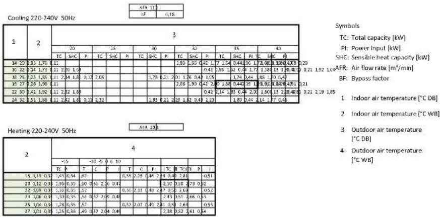
FTXM42M2V1B + RXM42MV1B
| AFR 11,2 | |
| BF | 0,15 |
Cooling 220-240V 50Hz
| 1 | 2 | 3 | ||||||||||||||||||
| 20 | 25 | 30 | 32 | 35 | 40 | |||||||||||||||
| TC | SHC | PI | TC | SHC | PI | TC | SHC | PI | TC | SHC | PI | TC | SHC | PI | TC | SHC | PI | |||
| 14 20 | 3,13 2,9 | 0 0,15 | 3 | 13 2,5 | 0 0,21 | 3,13 2 | 50 0,5 | 2 | 3,13 | 2,50 1,05 3,13 | 2,50 1 | 11 | 3,13 | 2,50 1,19 | ||||||
| 16 22 | 4,19 2,8 | 9 0,13 | 4,19 2,89 | 0,22 4,11 | 1 2,85 | 0,52 4 | 03 2,81 | 1,06 | 3,91 2,75 | 1,11 | 3,71 2 | 66 | 1,20 | |||||||
| 18 25 | 4,69 3,1 | 6 0,14 | 4,49 3,07 | 0,2 | 2 4,30 | 2,98 | 0,53 4,22 | 2,95 | 1,07 4,10 | 2,90 | 1,12 3,91 | 2,81 | 1,20 | |||||||
| 19 27 | 4,79 3,3 | 2 0,14 | 4 | 59 3,2 | 3 0,22 | 4,40 3 | 15 0,5 | 3 | 4,32 | 3,11 1,07 4,20 | 3,06 1 | 12 | 4,00 | 2,98 1,21 | ||||||
| 22 30 | 5,08 3,1 | 9 0,14 | 4,88 3,12 | 0,22 4,69 | 3,04 | 0,53 4 | 61 3,01 | 1,08 | 4,49 2,97 | 1,13 | 4,29 2,90 | 1,22 | ||||||||
| 24 32 | 5,27 3,1 | 0 0,14 | 5,07 3,03 | 0,2 | 2 4,88 | 2,97 | 0,54 4,80 | 2,94 | 1,08 4,68 | 2,90 | 1,13 4,91 | 2,83 | 1,22 | |||||||
| AFR 12,4 |
Heating 220-240V 50Hz
| 2 | 4 | ||||||||||
| -15 | -10 -5 0 6 10 | ||||||||||
| TC PI | TC PI | TC PI | TC PI | TC PI | TC PI | ||||||
| 15 2,57 0,84 | 3,09 0 89 3,6 | 1 | 0,93 4,85 1,22 5,59 | 1,28 6,07 | 1,32 | ||||||
| 20 2,41 0,87 | 2,93 0 91 3,4 | 5 0,95 | 4,67 1,25 | 5,40 1,31 5,19 1,35 | |||||||
| 22 2,35 0,88 | 2,87 0 92 3,3 | 1 | 0,96 4,59 1,26 5,33 | 1,32 5,81 | 1,36 | ||||||
| 24 2,29 0,89 | 2,80 0 93 3,3 | 2 0,97 | 4,52 1,27 | 5,25 1,33 5,74 1,38 | |||||||
| 25 2,25 0,89 | 2,77 0 93 3,2 | 1 | 0,98 4,48 1,27 5,21 | 1,34 5,65 | 1,38 | ||||||
| 27 2,19 0,90 | 2,71 0 94 3,2 | 5 0,99 | 4,41 1,29 | 5,14 1,35 5,13 1,39 | |||||||
Notes
- The capacities are based on the following conditions: Corresponding refrigerant piping length: 5.0 m Level difference: 0m
- The bold cells indicate the standard conditions. Rated operating frequency [Hz]
Symbols
TC: Total capacity [kW]
PI: Power input [kW]
SHC: Sensible heat capacity [kW]
AFR: Air flow rate [m^3/min]
BF: Bypass factor
1 Indoor air temperature [°C DB]
2 Indoor air temperature [°C WB]
3 Outdoor air temperature [°C DB]
4 Outdoor air temperature [°C WB]
3D098038
4 Capacity tables
4 - 1 Cooling/Heating Capacity Tables
FTXM50M2V1B + RXM50MV1B
| AFR 11,9 | |
| BF | 0,13 |
Cooling 220-240V 50Hz
| 1 | 2 | 3 | |||||||||||||||||
| 20 | 25 | 30 | 32 | 35 | 40 | ||||||||||||||
| TC | SHC | PI | TC | SHC | PI | TC | SHC | PI | TC | SHC | PI | TC | SHC | PI TC | SHC | P | |||
| 14 | 20 | 3,41 | 2,72 | 0,15 | 3,41 | 2,72 | 0,24 | 3,41 | 2,72 | 0,61 | 3,41 | 2,72 | 1,28 | 3,41 | 2,72 | 1,34 | 3,41 | 2,72 | 1,44 |
| 16 | 22 | 4,56 | 3,14 | 0,16 | 4,56 | 3,14 | 4,56 | 3,14 | 0,62 | 4,56 | 3,14 | 1,29 | 4,56 | 3,14 | 1,35 | 4,42 | 3,07 | 1,44 | |
| 18 | 25 | 5,58 | 3,66 | 0,16 | 5,35 | 3,55 | 0,26 | 5,12 | 3,45 | 0,63 | 5,02 | 3,40 | 1,29 | 4,88 | 3,34 | 1,36 | 4,65 | ||
| 19 | 27 | 5,70 | 3,83 | 0,17 | 5,47 | 3,72 | 0,26 | 5,23 | 3,62 | 0,63 | 5,14 | 3,58 | 1,30 | 5,00 | 3,52 | 1,36 | 4,77 | 3,42 | 1,45 |
| 22 | 30 | 6,04 | 3,68 | 0,17 | 5,81 | 3,59 | 5,26 | 5,58 | 3,50 | 0,64 | 5,49 | 3,46 | 1,30 | 5,35 | 3,40 | 1,37 | 5,11 | 3,32 | |
| 24 | 32 | 6,27 | 3,57 | 0,17 | 6,04 | 3,49 | 0,26 | 5,81 | 3,40 | 0,64 | 5,72 | 3,37 | 1,30 | 5,58 | 3,32 | 1,38 | 5,84 | ||
Heating 220-240V 50Hz
| AFR 13,3 |
| 2 | 4 | ||||||||||
| -15 -10 -5 | 0 6 10 | ||||||||||
| TC PI | TC PI | TC PI | TC PI | TC PI | TC PI | ||||||
| 15 2,76 0,93 | 3,32 0,98 | 3,88 | 1,03 5,21 1,35 6,00 | 1,42 6,52 | 1,47 | ||||||
| 20 2,59 0,96 | 3,15 1,07 | 3,71 | ,05 5,01 1,38 | 5,80 1,45 6,22 1,50 | |||||||
| 22 2,52 0,97 | 3,08 1,02 | 3,64 | 1,07 4,93 1,39 5,72 | 1,46 6,24 | 1,51 | ||||||
| 24 2,46 0,98 | 3,01 1,03 | 3,57 | ,08 4,85 1,40 | 5,64 1,48 6,16 1,52 | |||||||
| 25 2,42 0,99 | 2,98 1,03 | 3,54 | 1,08 4,81 1,41 5,60 | 1,48 6,12 | 1,53 | ||||||
| 27 2,35 1,00 | 2,91 1,04 | 3,47 | ,09 4,73 1,42 | 5,52 1,50 6,04 1,54 | |||||||
Notes
- The capacities are based on the following conditions: Corresponding refrigerant piping length: 5.0 m Level difference: 0m
- The bold cells indicate the standard conditions. Rated operating frequency [Hz]
Symbols
TC: Total capacity [kW]
PI: Power input [kW]
SHC: Sensible heat capacity [kW]
AFR: Air flow rate [m^3/min]
BF: Bypass factor
1 Indoor air temperature [°C DB]
2 Indoor air temperature [°C WB]
3 Outdoor air temperature [°C DB]
4 Outdoor air temperature [°C WB]
3D098039
4 Capacity tables
4 - 1 Cooling/Heating Capacity Tables
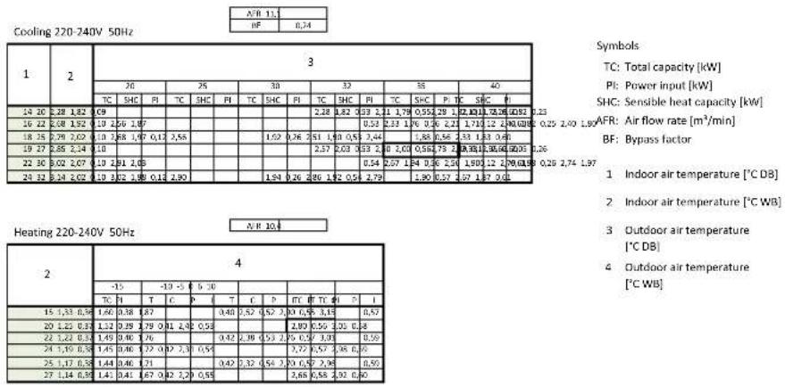
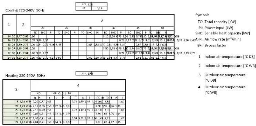
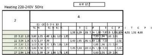
FTXM60M2V1B + RXM60M2V1B
| N 17, | ||||||||||||||||||||||
| BF | 6.17 | |||||||||||||||||||||
| 1 | 2 | 3 | ||||||||||||||||||||
| 20 | 25 | 30 | 32 | 35 | 40 | |||||||||||||||||
| IC | SIE | PI | IC | SIE | PI | IC | SIE | PI | IC | SIE | PI | IC | SIE | P | I | G | 9 | |||||
| 14 20 | 5.30 | 0.9 | 0.9 | 4.82 | 3.63 | 0.31 | 0.55 | 0.11 | 0.9 | 4.38 | 3.45 | 0.65 | 4.25 | 3.86 | 1.72 | 4.05 | 3.26 | 1.88 | ||||
| 16 22 | 6.31 | 0.8 | 0.8 | 5.03 | 4.05 | 0.33 | 5.76 | 3.93 | 0.81 | 66 | 3.87 | 1.87 | ||||||||||
| 18 | 25 | 6.70 | 4.39 | 0.20 | 6.42 | 4.26 | 0.34 | 6.14 | 4.14 | 4.16 | 832 | 6.02 | 4.08 | 1.67 | ||||||||
| 19 27 | 6.84 | 90 | 0.22 | 6.58 | 4.46 | 0.34 | 6.28 | 4.34 | 0.82 | 57 4.79 1.80 | ||||||||||||
| 22 | 30 | 7.25 | 4.41 | 0.22 | 6.97 | 4.30 | 0.34 | 6.70 | 4.29 | 9.83 | ||||||||||||
Symbols
TC: Total capacity [kW]
PI: Power input [kW]
C P SHC: Sensible heat capacity [kW]
AFR: Air flow rate [m^3/min]
BF: Bypass factor
1 Indoor air temperature (°C DB)
2 Indoor air temperature [°C WB]
3 Outdoor air temperature [°C DB]
4 Outdoor air temperature [°C WB]
Notes
-
The capacities are based on the following conditions: Corresponding refrigerant piping length: 5.0 m Level difference: 0m
-
The bold cells indicate the standard conditions. Rated operating frequency [Hz]
3D102183
4 Capacity tables
4 - 1 Cooling/Heating Capacity Tables
FTXM71M2V1B + RXM71M2V1B
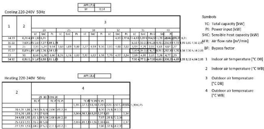
Notes
- The capacities are based on the following conditions: Corresponding refrigerant piping length: 5.0 m Level difference: 0m
- The bold cells indicate the standard conditions. Rated operating frequency [Hz]
3D105003
5 Dimensional drawings
5 - 1 Dimensional Drawings
RXM20-35M
3D099636
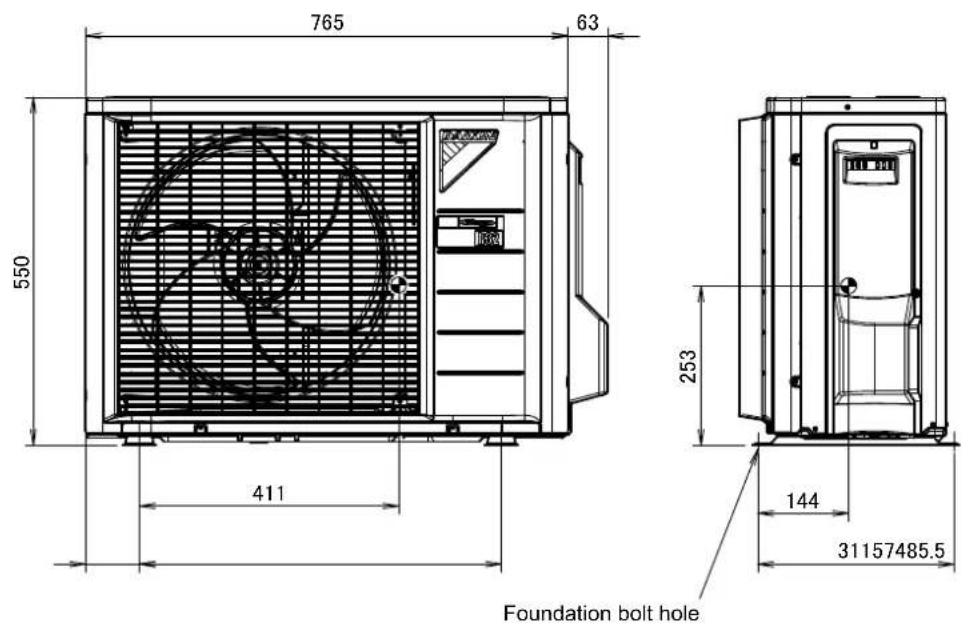
RXM42-50M
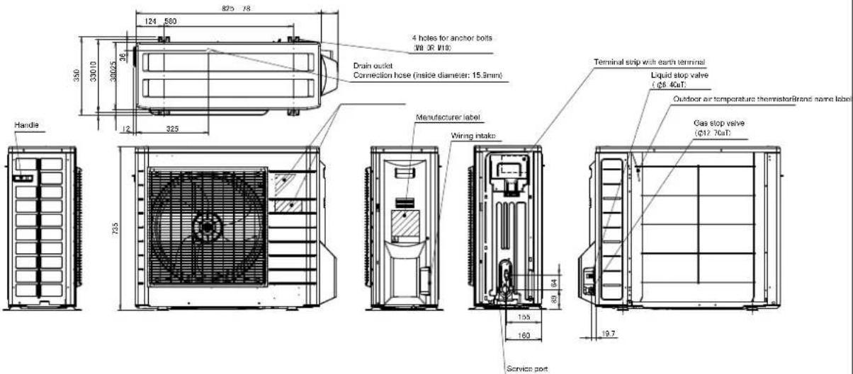
text_image
825 78 124 580 350 330/10 300/25 26 12 325 350 330/10 300/25 26 12 325 4 holes for anchor bolts (38 OR V19) Drain outlet Connection hose (inside diameter: 15.9mm) Handle 735 Manufacturer label Wiring intake Terminal stop with earth terminal Liquid stop valve (φ8.40μT) Outdoor air temperature thermometer Brand name label Gas stop valve (φ12.70μT) Service port 133 160 80 64 19.7Minimum space for air passage
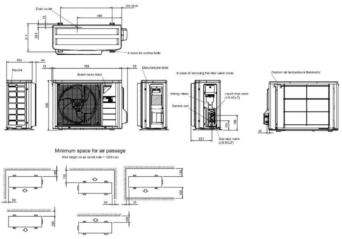
Wall height on air outlet side < 1200 mm
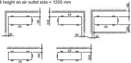
text_image
I height on air outlet side < 1200 mm 350 50 100 350 50 100 350In case of removing the stop valve cover.
3D092034A
5 Dimensional drawings
5 - 1 Dimensional Drawings
RXM60M
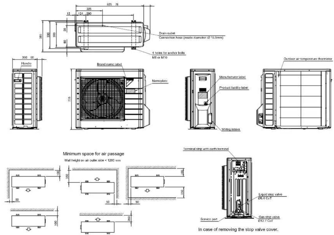
3D101541
RXM71M
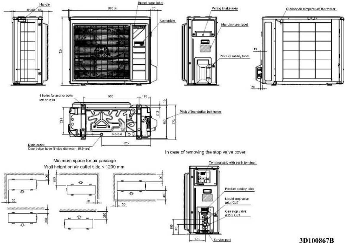
3D100867B
6 Centre of gravity
6 - 1 Centre of Gravity
RXM20-35M
Foundation bolt hole
4D099652
6 Centre of gravity
6 - 1 Centre of Gravity
RXM42-50M
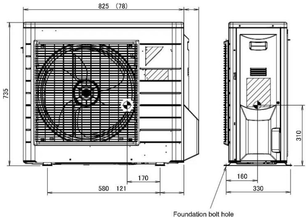
text_image
825 (78) 735 170 580 121 310 160 330 Foundation bolt hole4D092035A
6 Centre of gravity
6 - 1 Centre of Gravity
RXM60M
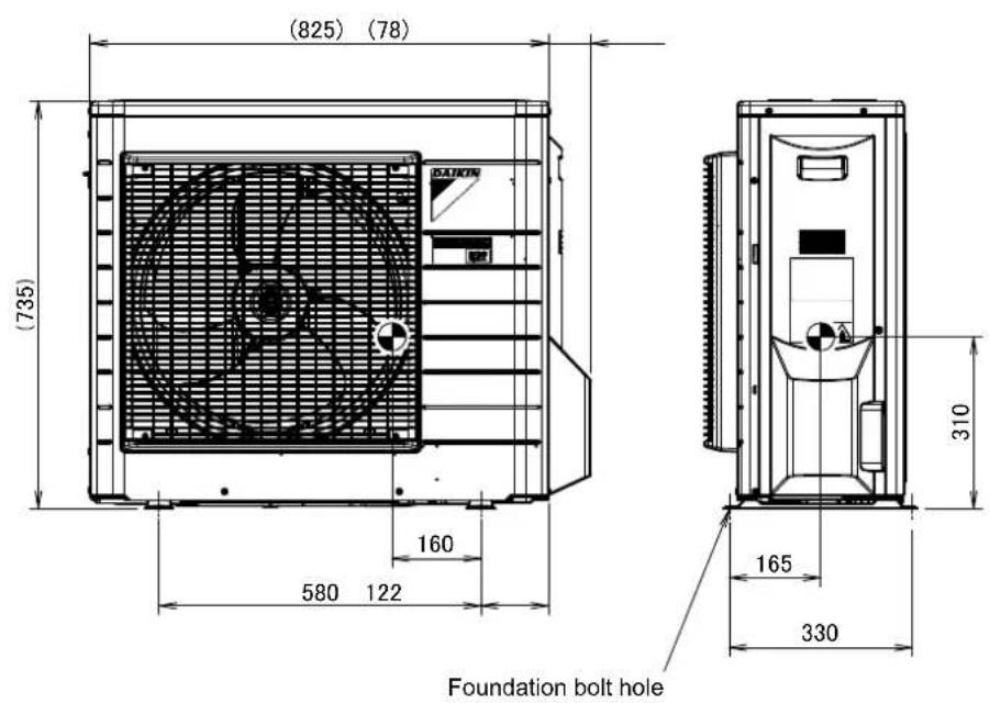
text_image
(825) (78) (735) 160 580 122 Foundation bolt hole 310 165 3304D102113
6 Centre of gravity
6 - 1 Centre of Gravity
RXM71M
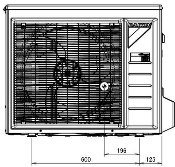
text_image
DAIKIN 600 196 125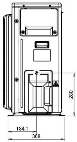
text_image
184.1 368 2804D100855
7 Piping diagrams
7 - 1 Piping Diagrams
RXM20-35M

flowchart
graph TD
    A["Heat exchanger"] --> B["Heating unit"]
    B --> C["Propeller fan"]
    C --> D["Muffler with filter"]
    D --> E["Mutter with filter"]
    E --> F["Motor-operated valve"]
    F --> G["Muffler with filter"]
    G --> H["Liquid stop valve"]
    H --> I["Field piping (6.40uL)"]
    I --> J["Field piping (9.50uL)"]
    J --> K["Grain flow: Cooling → Heating"]
    L["4-way valve ON: hozting"] --> M["Compressor"]
    N["Discharge pipe thermistor"] --> O["Muffler"]
    P["Accumulator"] --> Q["Condenser"]
    R["Refrigerant flow"] --> S["→ Cooling"]
    R --> T["→ Hozting"]
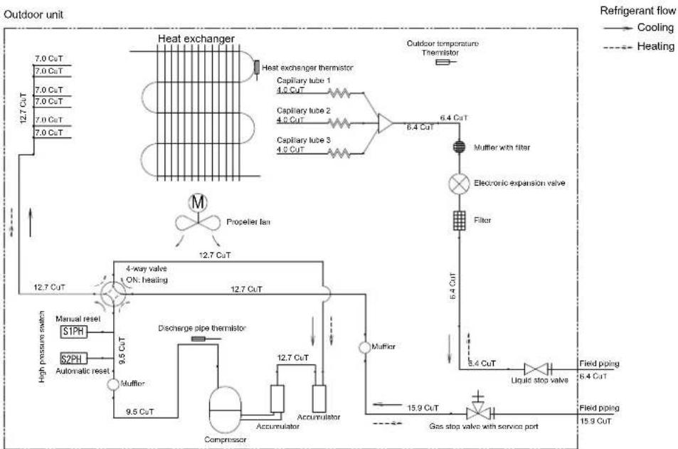
RXM42-50M
flowchart
graph TD
    A["Heat exchanger"] --> B["Heat exchanger thermometer"]
    B --> C["Propeller fan"]
    C --> D["4-way valve ON: heating"]
    D --> E["Muller"]
    E --> F["Discharge pipe thermometer"]
    F --> G["Compressor"]
    G --> H["Accumulator"]
    H --> I["Muffler"]
    I --> J["Muffler with filter"]
    J --> K["Electronic expansion valve"]
    K --> L["Receiver gas"]
    L --> M["Liquid stop valve"]
    M --> N["Field piping (6.40μl)"]
    N --> O["Gas stop valve with service port"]
    O --> P["Field piping (12.70μl)"]
    P --> Q["Refrigerant flow"]
    style A fill:#f9f,stroke:#333
    style B fill:#ccf,stroke:#333
    style C fill:#cfc,stroke:#333
    style D fill:#fcc,stroke:#333
    style E fill:#cff,stroke:#333
    style F fill:#ffc,stroke:#333
    style G fill:#cfc,stroke:#333
    style H fill:#fcc,stroke:#333
    style I fill:#cff,stroke:#333
    style J fill:#ffc,stroke:#333
    style K fill:#cfc,stroke:#333
    style L fill:#fcc,stroke:#333
    style M fill:#ffc,stroke:#333
    style N fill:#cfc,stroke:#333
    style O fill:#fcc,stroke:#333
    style P fill:#cfc,stroke:#333
    style Q fill:#fcc,stroke:#333
    style R fill:#ffc,stroke:#333
    style S fill:#cfc,stroke:#333
    style T fill:#fcc,stroke:#333
    style U fill:#cfc,stroke:#333
    style V fill:#fcc,stroke:#333
    style W fill:#cfc,stroke:#333
    style X fill:#fcc,stroke:#333
    style Y fill:#cfc,stroke:#333
    style Z fill:#fcc,stroke:#333
7 Piping diagrams
7 - 1 Piping Diagrams
RXM60M
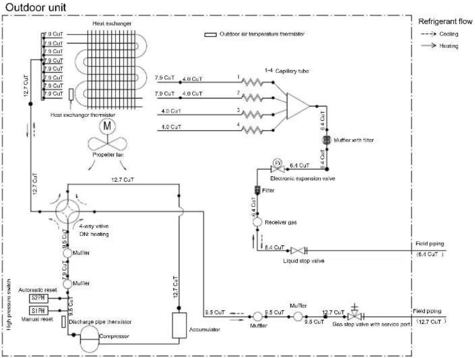
flowchart
graph TD
    A["Heat exchanger"] --> B["7.9 CuT"]
    A --> C["7.9 CuT"]
    A --> D["7.9 CuT"]
    A --> E["7.9 CuT"]
    A --> F["7.9 CuT"]
    A --> G["7.9 CuT"]
    A --> H["7.9 CuT"]
    A --> I["7.9 CuT"]
    A --> J["7.9 CuT"]
    A --> K["12.7 CuT"]
    K --> L["Propeller fan"]
    L --> M["12.7 CuT"]
    M --> N["4-way valve ON: heating"]
    N --> O["Muller"]
    O --> P["12.7 CuT"]
    P --> Q["Accumulator"]
    Q --> R["Discharge pipe thermistor"]
    R --> S["Compressor"]
    S --> T["Automatic reset S2PH"]
    S --> U["S1PH"]
    S --> V["Manual reset"]
    T --> W["High pressure switch"]
    U --> X["High pressure switch"]
    W --> Y["Electric expansion valve 6.4 CuT"]
    X --> Z["ReoRver gas 6.4 CuT"]
    Z --> AA["Liquid stop valve 6.4 CuT"]
    AA --> AB["Field piping (6.4 CuT)"]
    AB --> AC["Mufler 5.5 CuT"]
    AC --> AD["Mufler 3.5 CuT"]
    AD --> AE["Gas stop valve with service port 12.7 CuT"]
    AE --> AF["Fied piping (12.7 CuT)"]
    style A fill:#f9f,stroke:#333
    style AF fill:#ccf,stroke:#333
    note right of A
        Outdoor air temperature thermistor
        1-4 Capillary tube
        1-4 Capillary tube
        1-4 Capillary tube
        1-4 Capillary tube
        1-4 Capillary tube
        1-4 Capillary tube
        1-4 Capillary tube
        1-4 Capillary tube
        1-4 Capillary tube
        1-4 Capillary tube
        1-4 Capillary tube
        1-4 Capillary tube
3D101185
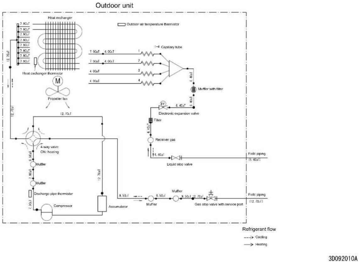
RXM71M
flowchart
graph TD
    A["Outdoor unit"] --> B["Heat exchanger"]
    B --> C["Capillary tube 1: 4.0 CuT"]
    B --> D["Capillary tube 2: 4.5 CuT"]
    B --> E["Capillary tube 3: 4.5 CuT"]
    C --> F["Mutter with filter"]
    D --> F
    E --> F
    F --> G["Electronic expansion valve"]
    G --> H["Filter"]
    H --> I["Gas stop valve with service port"]
    I --> J["Liquid stop valve"]
    J --> K["Field piping 6.4 CuT"]
    I --> L["Field piping 15.9 CuT"]
    M["Propeller fan"] --> N["4-way valve ON: heating"]
    O["Manual reset S1PH"] --> P["9.5 CuT"]
    Q["S2PH"] --> R["Muffler"]
    S["High pressure switch"] --> T["9.5 CuT"]
    U["Compressor"] --> V["Accumulator"]
    W["Discharge pipe thermistor"] --> X["12.7 CuT"]
    Y["Electricity expansion valve"] --> Z["6.4 CuT"]
    AA["Refrigerant flow"] --> AB["Cooling"]
    AA --> AC["Heating"]
3D100850B
8 Wiring diagrams
8 - 1 Wiring Diagrams - Single Phase
RXM20-35M
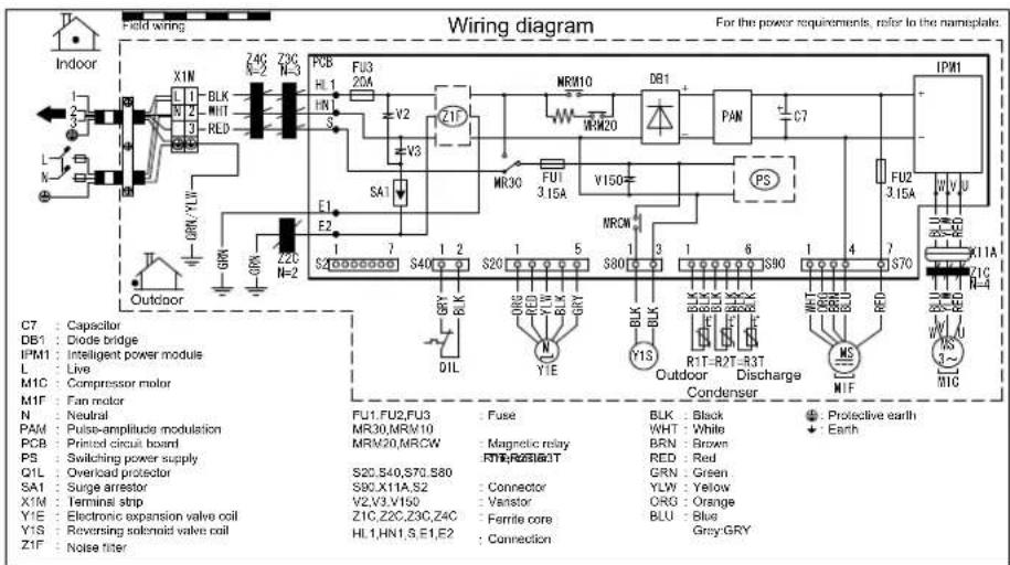
text_image
Wiring diagram For the power requirements, refer to the nameplate. Indoor C7 : Capacitor DB1 : Diode bridge IPM1 : Intelligent power module L : Live M1C : Compressor motor M1F : Fan motor N : Neutral PAM : Pulse-amplitude modulation PCB : Printed circuit board PS : Switching power supply Q1L : Overload protector SA1 : Surge arrester X1M : Terminal strip Y1E : Electronic expansion valve coil Y1S : Reversing solenoid valve coil Z1F : Noise titer Field wiring Z4G N=2 Z3C N=3 PCB HL1 FL3 20A V2 V3 MR810 MRM20 DR1 PAN C7 FRK Y1V 3 S4 7 S40 S20 S80 S30 BLK RCL BLK GRY BLK Y1E MND RLK BLK RCL BLK GRY BLK Y1S R1T-R2T-R3T Outdoor Discharge Condenser MS MIF Protective earth + BLK Black Protection earth WHT White Earth BRN Brown Earth RED Red Earth GRN Green Earth YLW Yellow Earth ORG Orange Earth BLU Blue Earth Grey-GRYNotes
Size: 140 x 80
Refer to purchasing specification AS303002, unless otherwise specified.
4D099916B
8 Wiring diagrams
8 - 1 Wiring Diagrams - Single Phase
RXM42-50M
flowchart
graph TD
    A["Power Supply Line"] --> B["PDB1"]
    B --> C["Switch"]
    C --> D["Relay"]
    D --> E["Capacitor"]
    E --> F["Transistor"]
    F --> G["Ground"]
    style A fill:#f9f,stroke:#333
    style B fill:#ccf,stroke:#333
    style C fill:#cfc,stroke:#333
    style D fill:#fcc,stroke:#333
    style E fill:#cff,stroke:#333
    style F fill:#ffc,stroke:#333
    style G fill:#fcf,stroke:#333
Notes
1. Size: length 105 X width 185.
2. Refer to purchasing specification AS303002, unless otherwise specified
3D090522A
RXM60-71M
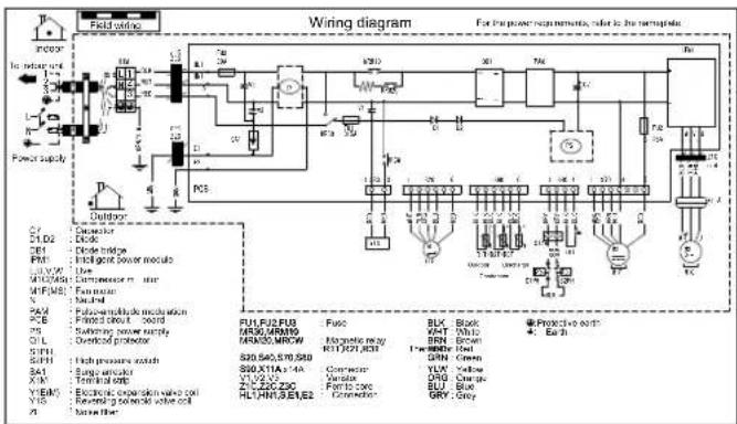
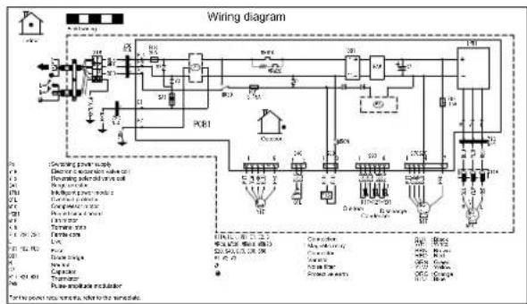
text_image
Wiring diagram For purpose requirements, color is the necessary. Field wiring in rear Power supply PC3 Outdoor C1 C1D2 CE1 PM1 M1V201 M1F202 P4A P5 Q1L SP11 SP19 S41 X4 Y18N5 Y15 A PC3 F01,P02,P03 MR30,MRCW0 MR30,MRCW S20,S40,S70,S80 S60,S11A,S14A VL1,VL2,VL3 VL4,VL5,VL6,VL7,VL8,VL9,VL10,VL11,VL12,VL13,VL14,VL15,VL16,VL17,VL18,VL19,VL20,VL21,VL22,VL23,VL24,VL25,VL26,VL27,VL28,VL29,VL30,VL31,VL32,VL33,VL34,VL35,VL36,VL37,VL38,VL39,VL40,VL41,VL42,VL43,VL44,VL45,VL46,VL47,VL48,VL49,VL50,VL51,VL52,VL53,VL54,VL55,VL56,VL57,VL58,VL59,VL60,VL61,VL62,VL63,VL64,VL65,VL66,VL67,VL68,VL69,VL70,VL71,VL72,VL73,VL74,VL75,VL76,VL77,VL78,VL79,VL80,VL81,VL82,VL83,VL84,VL85,VL86,VL87,VL88,VL89,VL90,VL91,VL92,VL93,VL94,VL95,VL96,VL97,VL98,VL99,VL100 Fuel Motorcycle reset RUT,RST,RCH Motorcycle reset RLT,RST,RCH RLT,RST,RCH RLT,RST,RCH RLT,RST,RCH RLT,RST,RCH RLT,RST,RCH RLT,RST,RCH RLT,RST,RCH RLT,RST,RCH RLT,RST,RCH RLT,RST,RCH RLT,RST,RCH RLT,RST,RCH RLT,RST,RCH RLT,RST,RCH BLK VHT BRN TRW GRN YUV DRG BUT GRY BLY GLYNotes
1. Size: length 105 X width 185
2. Refer to purchasing specification AS(Y)303002, unless otherwise specified
3D100894A
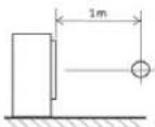
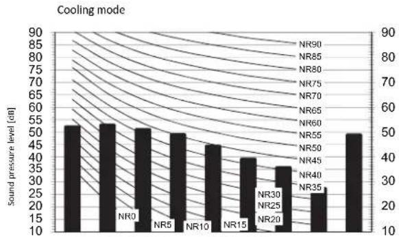
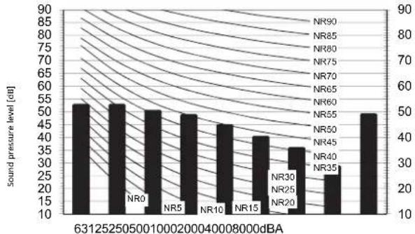
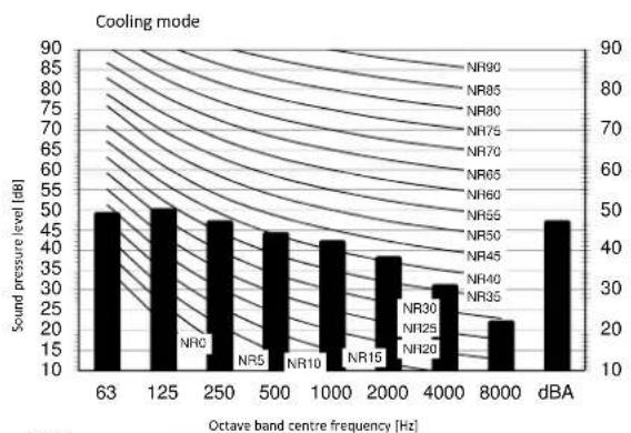
9 Sound data
9 - 1 Sound Pressure Spectrum
RXM20M
bar
| Octave band centre frequency [Hz] | Sound pressure level [dB] | | --------------------------------- | ------------------------- | | 63125250500 | 50 | | 100002000400 | 50 | | 800008000 | 45 | | 100000 | 40 | | 80000 | 35 | | 63125250 | 30 | | 10000200 | 25 | | 80000 | 20 | | 6312525 | 15 | | 100000 | 10 |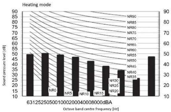
bar
| Octave band centre frequency [Hz] | Sound pressure level [dB] | | --------------------------------- | ------------------------- | | 631 | 50 | | 125 | 50 | | 25 | 50 | | 50 | 50 | | 100 | 48 | | 200 | 47 | | 200 | 44 | | 400 | 43 | | 800 | 39 | | 1600 | 35 | | 3300 | 27 | | 661 | 48 |Legend
dBA = A-weighted sound pressure level (A scale according to IEC).

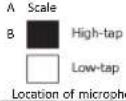
Cooling
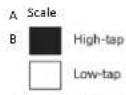
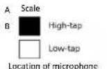
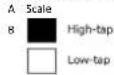
| A | B |
| dBA | 46 47 |
Heating
Total dB
| A | B |
| dBA |
Notes
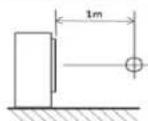
1 Background noise already taken into account.
- Operating conditions: power source 220-240 V/220 V 50/60 Hz; JIS standard
3 Operating noise varies depending on operation and ambient conditions.
4 The operation noise measuring method is in accordance with JISC9612.
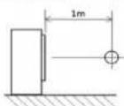
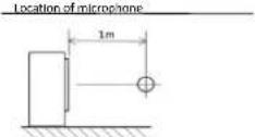
5 Measuring location: anechoic chamber
3D099853
RXM25M

bar
| Octave band centre frequency [Hz] | Sound pressure level [dB] | | --------------------------------- | ------------------------- | | 63 | 48 | | 125 | 50 | | 250 | 48 | | 500 | 46 | | 1000 | 42 | | 2000 | 36 | | 4000 | 32 | | 8000 | 24 | | dBA | 46 |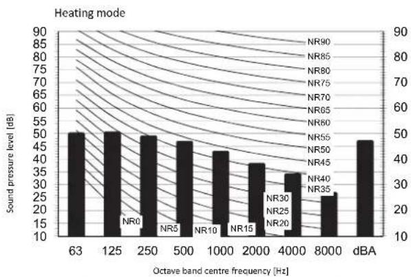
bar
| Octave band centre frequency [Hz] | Sound pressure level [dB] | | --------------------------------- | ------------------------- | | 63 | 50 | | 125 | 50 | | 250 | 50 | | 500 | 48 | | 1000 | 44 | | 2000 | 38 | | 4000 | 34 | | 8000 | 26 | | dBA | 48 |Legend
dBA = A-weighted sound pressure level (A scale according to IEC).
Cooling
Total dB
| A | B |
| dBA | 46 |
Heating
Total dB
| A | B |
| dBA | 47 |
Notes
1 Background noise already taken into account.
2 Operating conditions: power source 220-240 V/220 V 50/60 Hz; JIS standard
3 Operating noise varies depending on operation and ambient conditions.
4 The operation noise measuring method is in accordance with JISC9612.
5 Measuring location: anechoic chamber
3D099854A
9 Sound data
9 - 1 Sound Pressure Spectrum
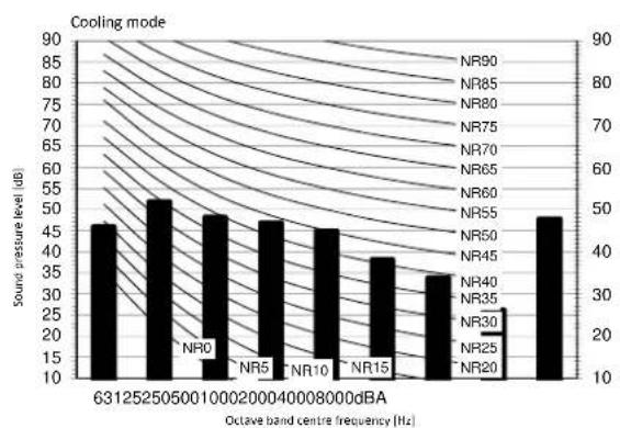
RXM35M
bar
| Noise Level | Sound Pressure Level (dB) | | ----------- | ------------------------- | | NR0 | 52 | | NR5 | 54 | | NR10 | 50 | | NR15 | 45 | | NR20 | 38 | | NR25 | 35 | | NR30 | 28 | | NR35 | 50 |631252505001000200040008000dBA
Octave band centre frequency [Hz]
Heating mode
bar
| Label | Sound pressure level [dB] | |-------|---------------------------| | NR0 | 50 | | NR5 | 50 | | NR10 | 45 | | NR15 | 40 | | NR20 | 35 | | NR30 | 30 | | NR25 | 25 | | NR35 | 20 |Octave band centre frequency [Hz]
Legend
dBA = A-weighted sound pressure level (A scale according to IEC).
Cooling Total dB
| A | B |
| dBA | 49 49 |
Heating
Total dB
| A | B |
| dBA |
Notes
1 Background noise already taken into account.
2 Operating conditions: power source 220-240 V/220 V 50/60 Hz; JIS standard
3 Operating noise varies depending on operation and ambient conditions.
4 The operation noise measuring method is in accordance with JISC9612.
5 Measuring location: anechoic chamber
3D099855A
RXM42M
bar
| Noise Level | Sound Pressure Level [dB] | | ----------- | ------------------------- | | NR0 | 55 | | NR5 | 50 | | NR10 | 45 | | NR15 | 40 | | NR20 | 30 | | NR25 | 25 | | NR30 | 20 | | NR35 | 15 |631252505001000200040008000dBA
Octave band centre frequency [Hz]
Heating mode
bar
| Category | Sound pressure level [dB] | | -------- | ------------------------- | | NR0 | 57 | | NR5 | 49 | | NR10 | 46 | | NR15 | 45 | | NR20 | 38 | | NR25 | 30 | | NR30 | 23 | | NR35 | 49 |631252505001000200040008000dBA
Octave band centre frequency [Hz]
Legend
dBA = A-weighted sound pressure level (A scale according to IEC).

Cooling Total dB
| A | B |
| dBA | 48 48 |
Heating
Total dB
| A | B |
| dBA |
Notes
1 Background noise already taken into account.
2 Operating conditions: power source 220-240 V/220 V 50/60 Hz; JIS standard
3 Operating noise varies depending on operation and ambient conditions.
4 The operation noise measuring method is in accordance with JISC9612.
5 Measuring location: anechoic chamber
3D098035A
9 Sound data
9 - 1 Sound Pressure Spectrum
RXM50M
bar
| Octave band centre frequency [Hz] | Sound pressure level [dB] | | --------------------------------- | ------------------------- | | 63 | 50 | | 125 | 50 | | 250 | 45 | | 500 | 45 | | 1000 | 40 | | 2000 | 35 | | 4000 | 30 | | 8000 | 25 | | dBA | 45 |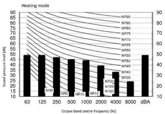
bar
| Octave band centre frequency [Hz] | Sound pressure level [dB] | | --------------------------------- | ------------------------- | | 63 | 50 | | 125 | 50 | | 250 | 48 | | 500 | 45 | | 1000 | 45 | | 2000 | 40 | | 4000 | 35 | | 8000 | 25 | | dBA | 50 |Legend
dBA = A-weighted sound pressure level (A scale according to IEC).
Cooling
Total dB
| A | B |
| dBA | 48 49 |
Heating
| Total dB | |
| A | B |
| dBA | |
Notes
1 Background noise already taken into account.
2 Operating conditions: power source 220-240 V/220 V 50/50 Hz; JIS standard
3 Operating noise varies depending on operation and ambient conditions.
4 The operation noise measuring method is in accordance with JISC9612.
5 Measuring location: anechoic chamber
3D098036A
9 Sound data
9 - 1 Sound Pressure Spectrum
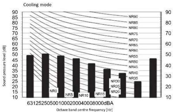
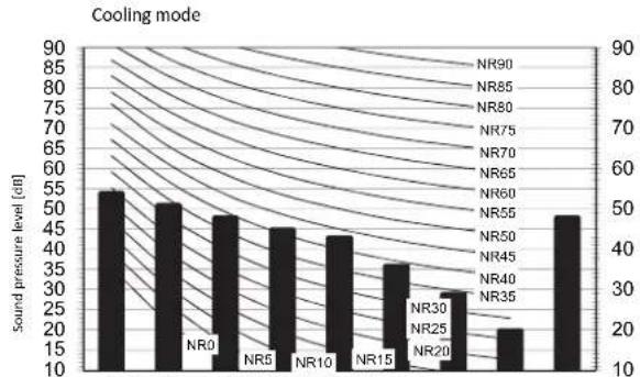
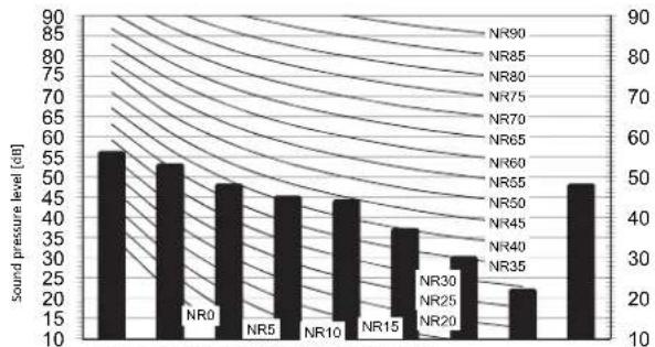
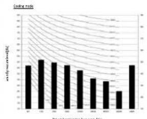
RXM60M
bar
| Octave band centre frequency (Hz) | Sound pressure level (dB) | | --------------------------------- | ------------------------- | | 631 | 47 | | 25 | 52 | | 50 | 49 | | 00 | 48 | | 100 | 47 | | 200 | 46 | | 400 | 45 | | 800 | 39 | | 0000 | 34 | | 2000 | 25 | | 8000 | 49 |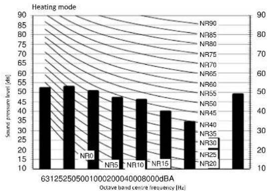
bar
| Octave band centre frequency [Hz] | Source pressure level [dB] | | --------------------------------- | -------------------------- | | 6312525050010000200040008000dBA | 50 | | NR0 | 50 | | NR5 | 45 | | NR10 | 45 | | NR15 | 40 | | NR25 | 35 | | NR20 | 50 |Legend
dBA = A-weighted sound pressure level (A scale according to IEC).
Cooling
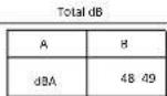
| Heating | Total dB | |
| A | B | |
| dBA | ||
Notes
1 Background noise already taken into account.
2 Operating conditions: power source 220-240 V/220 V 50/60 Hz; JIS standard
3. Operating noise varies depending on operation and ambient conditions.
4 The operation noise measuring method is in accordance with JISC9612.
5 Measuring location: anechoic chamber
3D102112
RANTIN
bar
| Category | across-median BMI | |---|---| | 1 | 0.75 | | 2 | 0.85 | | 3 | 0.82 | | 4 | 0.78 | | 5 | 0.65 | | 6 | 0.62 | | 7 | 0.55 | | 8 | 0.45 | | 9 | 0.88 |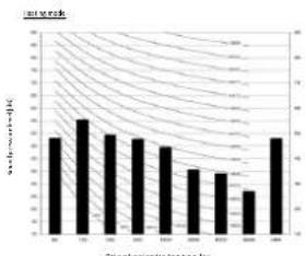
bar
| Category | Value | |---|---| | 1 | 4.5 | | 2 | 6.0 | | 3 | 5.0 | | 4 | 5.0 | | 5 | 4.5 | | 6 | 3.5 | | 7 | 3.0 | | 8 | 2.0 | | 9 | 4.0 | | 10 | 5.0 |

Workei
- Exposed on a very possible error
- 100% of the company's shareholding in 2013 was \$57.9 million, including
- The following table provides the information in English:
- The species are varying from the 1980s to 1990s.

30105011
10 Operation range
10 - 1 Operation Range
RXM20-50M
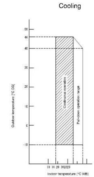
bar
| Indoor temperature [°C WB] | Outdoor temperature [°C DS] | | -------------------------- | ---------------------------- | | 10 | - | | 14 | - | | 20 | 46 | | 30 | 46 | | 302823 | 46 | | Full-down operation range | 40 |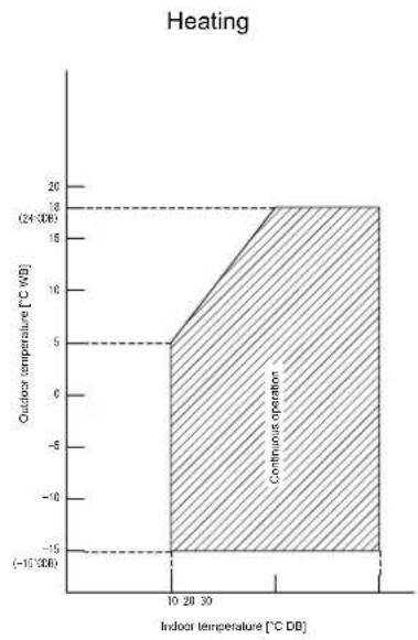
line
| Indoor temperature [°C DB] | Outdoor temperature [°C WB] | | -------------------------- | --------------------------- | | 10 | -15 | | 20 | 5 | | 30 | 18 |Notes 1. The graph is based on the following conditions. Corresponding refrigerant piping length: 5 m Level difference: 0 m Air flow rate High
3D092127C
RXM60-71M
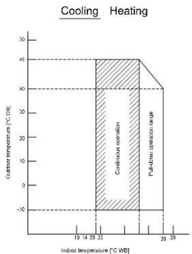
bar
| Indoor temperature [°C WB] | Outdoor temperature [°C DB] | | -------------------------- | --------------------------- | | 10 | -10 | | 14 | -10 | | 20 | -10 | | 23 | 48 | | 27 | 48 | | 30 | 48 |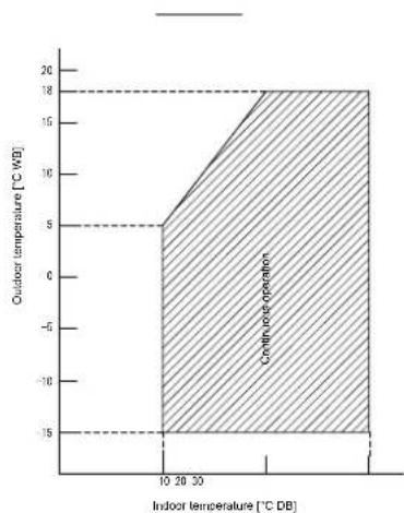
area
| Indoor temperature [°C DB] | Outdoor temperature [°C WB] | | :--- | :--- | | 10 | -15 | | 20 | -15 | | 30 | -15 | | 40 | -15 | | 50 | -15 | | 60 | -15 | | 70 | -15 | | 80 | -15 | | 90 | -15 | | 100 | -15 | | 110 | -15 | | 120 | -15 | | 130 | -15 | | 140 | -15 | | 150 | -15 | | 160 | -15 | | 170 | -15 | | 180 | -15 | | 190 | -15 | | 200 | -15 | | 210 | -15 | | 220 | -15 | | 230 | -15 | | 240 | -15 | | 250 | -15 | | 260 | -15 | | 270 | -15 | | 280 | -15 | | 290 | -15 | | 300 | -15 | | 310 | -15 | | 320 | -15 | | 330 | -15 | | 340 | -15 | | 350 | -15 | | 360 | -15 | | 370 | -15 | | 380 | -15 | | 390 | -15 | | 400 | -15 | | 410 | -15 | | 420 | -15 | | 430 | -15 | | 440 | -15 | | 450 | -15 | | 460 | -15 | | 470 | -15 | | 480 | -15 | | 490 | -15 | | 500 | -15 | | 510 | -15 | | 520 | -15 | | 530 | -15 | | 540 | -15 | | 550 | -15 | | 560 | -15 | | 570 | -15 | | 580 | -15 | | 590 | -15 | | 600 | -15 | | 610 | -15 | | 620 | -15 | | 630 | -15 | | 640 | -15 | | 650 | -15 | | 660 | -15 | | 670 | -15 | | 680 | -15 | | 690 | -15 | | 700 | -15 | | 710 | -15 | | 720 | -15 | | 730 | -15 | | 740 | -15 | | 750 | -15 | | 760 | -15 | | 770 | -15 | | 780 | -15 | | 790 | -15 | | 800 | -15 | | 810 | -15 | | 820 | -15 | | 830 | -15 | | 840 | -15 | | 850 | -15 | | 860 | -15 | | 870 | -15 | | 880 | -15 | | 890 | -15 | | 900 | -15 | | 910 | -15 | | 920 | -15 | | 930 | -15 | | 940 | -15 | | 950 | -15 | | 960 | -15 | | 970 | -15 | | 980 | -15 | | 990 | -15 | | 1000 | -15 |Notes. 1. The graphs is based on the following conditions. Corresponding refrigerant piping length: 5 in Level difference: 0m Air flow rate High
3D100846
Daikin Europe N.V. Naamloze Vennootschap - Zandvoordestraat 300, B-8400 Oostende - Belgium - www.daikin.eu - BE 0412 120 336 - RPR Oostende

natural_image
Blank white image with a thin border (no text, symbols, or markings)
EEDEN XXX-06/16

Daikin Europe N.V. participates in the Eurovent Certification programme for Liquid Chilling Packages (LCP), Air handling units (AHU), Fan coil units (FCU) and variable refrigerant flow systems (VRF). Check ongoing validity of certificate online: www.eurovent-certification.com or using: www.certiflash.com

The present leaflet is drawn up by way of information only and does not constitute an offer binding upon Daikin Europe N.V.. Daikin Europe N.V. has compiled the content of this leaflet to the best of its knowledge. No express or implied warranty is given for the completeness, accuracy, reliability or fitness for particular purpose of its content and the products and services presented therein. Specifications are subject to change without prior notice. Daikin Europe N.V. explicitly rejects any liability for any direct or indirect damage, in the broadest sense, arising from or related to the use and/or interpretation of this leaflet. All content is copyrighted by Daikin Europe N.V.