
KRCS01-5B - Klimaanlæg DAIKIN - Gratis brugsanvisning og manual
Find enhedens vejledning gratis KRCS01-5B DAIKIN i PDF-format.


Brugerspørgsmål om KRCS01-5B DAIKIN
0 spørgsmål om dette apparat. Besvar dem du kender, eller stil dit eget.
Stil et nyt spørgsmål om dette apparat
Download vejledningen til din Klimaanlæg i PDF-format gratis! Find din vejledning KRCS01-5B - DAIKIN og tag din elektroniske enhed tilbage i hånden. På denne side er alle dokumenter nødvendige for brugen af din enhed offentliggjort. KRCS01-5B af mærket DAIKIN.
BRUGSANVISNING KRCS01-5B DAIKIN
DAIKIN Air Conditioners
Remote
Sensor
Installation Manual
KRCS01-5B 3P657596-1 Be sure to read this installation manual before conducting the installation of this product. Installation must be conducted according to this manual.
(Caution) Local setting for case of Skyair
- Case of installing to Skyair, make sure the set to local settings after mounted remote sensor.
- SECOND CODE No. change must be conducted according to following table, from "02" to "01".
| Default | Changed | ||
| Mode No. | FIRST CODE No. | SECOND CODE No. | SECOND CODE No. |
| 15 (25) | 10 02 01 | ||
Setting detail be refer to ③ Local setting
- Make sure the no errors be sure to operation test after local setting.
Notes) Comfortable eco-dry control function is not work in case of installing to comfortable eco-dry control function by humidity detection supported models
Accessories description
Check it the following accessories are attached to this product.
| Name | Sensor box | Extension cable (2-core, 12m) | Clamp | Mounting screw (M4×16) | Other |
| Quantity | 1 pc. | 1 pc. | 1 pc.2 pc | ||
| Shape | • Installation manual |

Mounting the Sensor box
(1) Selection of mounting location.
Sensor box (1) have thermistor for temperature detection built-in.
Select the mounting location taking the following cautions into account.
-
Where the average temperature of an air conditioned room can be detected.
-
Where it is not exposed to the direct sunlight.
-
Where it is not influenced by other heat sources.
-
Where it is not exposed to the direct discharge air from the air conditioner.
-
Where it is not exposed to the outdoor air infiltrated into the room by opening the door.
(2) Mounting
- Remove the cover of the sensor box (1).

Sensor box (1)
Insert a flat blade screw driver into the sensor box (1) concave part (2 locations). Remove the cover pushing up the hook to the cover of the sensor box (1).
Do not push the nail powerfully with a narrow flat blade screw driver, because you may break off the hook.
1 When mounting on the wall
Thermal insulation material
Mounting screw (4)

Knockout hole
r cable
Sensor box (1)
Air hole
Release
paper
Sensor box cover

Wall surface mounting holes
(unit : mm)
Figure 1
)
- Break open the knockout hole in the sensor box (1) with a nipper or a similar tool. Pass the extension cable (2) through the hole and fasten the wires to the terminals with screws.
- To avoid tensile force on the terminals, pass the attached clamp (3) through the holes shown in the below right figure and tighten the extension cable (2) with the attached clamp (3) at the sheathed part.
ANThe knot must come to the box inside.)
Please cut excess clamp for base after fixing.
Clamp (3)

- Screw the sensor box (1) to the wall surface with mounting screw (4) (M4×16, 2 places).
Wall surface mounting holes dimension refer to Figure 1. If the sensor box cannot be screwed to wall surface, tear off the released paper and mount it on the wall surface.
② For embedded wiring
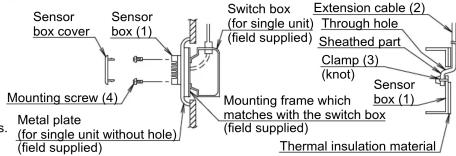
- Pass the extension cable (2) through the sensor box (1) cable hole and carry out the wiring
- Pass the attached clamp (3) through the clamp
- Pass the attached clamp (3) through the clamp holes and tighten the extension cable (2) at the sheathed part as shown in the upper right figure Please cut excess clamp for base after fixing.
- Tap M4 screw holes in the metal plate (field supplied) as shown in the right drawing and mount the switch box on the metal plate. Refer to Figure 2.
- When wiring the extension cable (2), the air holes of sensor box (1) will not be blocked.
- When the extension cable is longer than necessary, cut it to the appropriate length, peel the insulation, attach the ring type crimp style terminal for M3 (field supplied) and carry out the wiring. The length of insulation to be peeled off is as shown below.
(Work carefully so that the connector side may not be cut.)


Wiring method
Connect the extension cable (2) connector side to the indoor unit PCB (printed circuit board) For connection to the indoor unit, follow the procedure shown below.
Caution
- Make sure to turn off the power supply before starting the wiring work and do not turn on until all the work is completed.
Read also the installation manual and the wiring diagram of the indoor unit when carrying out the work. -
When wiring the extension cable (2), do not pass where the extension cable (2) may be affected by the power line or noise.
-
Make sure to securely connect the connectors.
Defective connection may result in incorrect detection of room temperature or malfunction.
-
Do not splice wires.
-
Lay and clamp the extension cable (2) inside the indoor unit switch box just like the low voltage line (cord for remote controller). And do not pass where the extension cable inside the indoor unit switch box may be affected by the power line (cord for the indoor unit and the other electric line).
-
When wiring to the indoor unit PCB, remove the existing sensor from PCB (X16A).
-
Extension cable (2) connect to PCB (X16A).

flowchart
graph TD
    A["Terminal connection"] --> B["Sensor box (1)"]
    B --> C["Connector connection"]
    C --> D["Extension cable (2)"]
    D --> E["Indoor unit"]
    E --> F["X16A"]
    F --> G["2. Connect Printed circuit board (PCB)"]
    G --> H["Existing sensor"]
    H --> I["1. Remove"]
- Lay and clamp the extension cable (2) inside the indoor unit switch box just like the low voltage wire (remote controller wiring). When doing this work, keep a certain distance between the high voltage wiring and the low voltage wiring to avoid error of sensor. Provide protection of the existing cable for sensor without touching indoor unit PCB.

Please cut excess clamp for base after fixing.
- Fit the sensor box cover into the sensor box (1).

Local setting
- Make sure the completing all work of indoor and outdoor unit.
- Make sure the closing switch box cover of indoor unit, casing for outdoor unit and cover for piping.
Set the local setting by remote controller after turn on. - Local setting set by changing three of "Mode No.", "FIRST CODE No.", "SECOND CODE No."
- Setting procedure and operating method refer to installing manual attach to remote controller.
Notes) "Mode No." setting be done to group together.
Case of each indoor units setting or setting confirmation.
set to number in ( ) of "Mode No." - SECOND CODE No. change must be conducted according to following
| Table, from "02" to "01". | Default | Changed | |
| Mode No.(Notes) | FIRST CODE No. S | SECOND CODE No. | SECOND CODE No. |
| 15 (25) 10 | 02 01 | ||
- After changed to settings, Turn off and turn on again

Operation test after mounting the sensor
After the sensor is installed and the wiring is completed, conduct cooling and heating operation in order to make sure of detecting temperature accurately (not to be uncooled or unheated).


Mærke : DAIKIN
Model : KRCS01-5B
Kategori : Klimaanlæg