RMK-3 - Radio ICOM - Gratis brugsanvisning og manual
Find enhedens vejledning gratis RMK-3 ICOM i PDF-format.


Brugerspørgsmål om RMK-3 ICOM
0 spørgsmål om dette apparat. Besvar dem du kender, eller stil dit eget.
Stil et nyt spørgsmål om dette apparat
Download vejledningen til din Radio i PDF-format gratis! Find din vejledning RMK-3 - ICOM og tag din elektroniske enhed tilbage i hånden. På denne side er alle dokumenter nødvendige for brugen af din enhed offentliggjort. RMK-3 af mærket ICOM.
BRUGSANVISNING RMK-3 ICOM
Thank you for purchasing the RMK-3 SEPARATION KIT. The RMK-3 allows you to install the mobile transceiver front panel separately from the main body for added installation convenience and operation. Use either the optional OPC-607, OPC-608 or OPC-609 SEPARATION CABLE with the RMK-3.
- In this instruction, the illustration is described using the IC-F5060 series transceiver.
■Supplied accessories
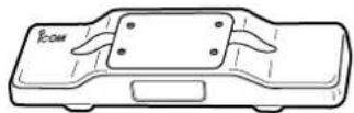
Main body attachment
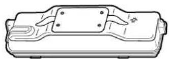
Front panel attachment
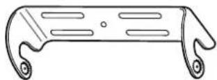
Mounting bracket
Flat cable
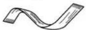
Flat washers (M5)

Spring washers (M5)

Nuts (M5)

Mounting screws (M5·12)

Self-tapping screws (M5·16)

Bracket screws

Separation
CAUTION! To avoid damage to the transceiver, turn the power OFF before separating the front panel from the main body.
The optional OPC-607 (3 m; 9.84 ft), OPC-608 (8 m; 26.3 ft) or OPC-609* (1.9 m; 6.3 ft) SEPARATION CABLE is required for installing the transceiver front panel and main body separately. *For Europe version, only the OPC-609 is available.
①Turn the transceiver's power OFF, then disconnect the DC power cable.
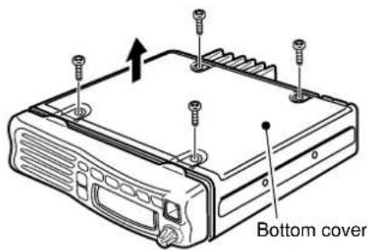
②Unscrew the 4 bottom screws, then remove the bottom cover from the transceiver in the direction of the arrow.
text_image
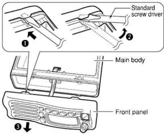
Bottom cover③Remove the front panel from the main body using a standard screw driver as shown below.
text_image
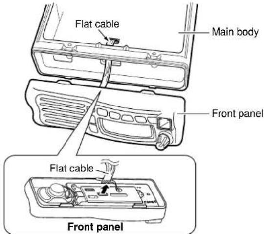
Standard screw driver Main body Front panel④Disconnect the flat cable from the front panel.
text_image
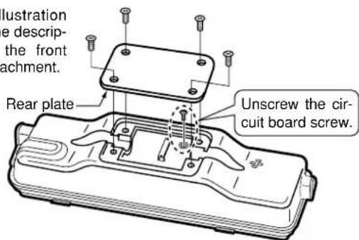
Flat cable Main body Front panel Flat cable Front panel⑤Unscrew the 4 rear plate screws, then remove the rear plates from both the front panel and main body attachments.
*This illustration shows the description for the front panel attachment.
text_image
Illustration e descrip- the front achment. Rear plate Unscrew the cir- cuit board screw.Continue to the back page.
Icom, Icom Inc. and the Yogomare registered trademarks of Icom Incorporated (Japan) in the United States, the United Kingdom, Germany, France, Spain, Russia and/or other countries.
■Attachment
For the front panel attachment:
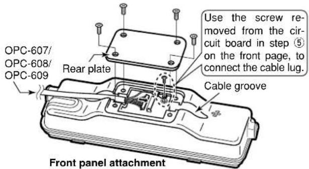
①Connect the optional OPC-607, OPC-608 or OPC-609 to the front panel attachment as shown below.
After the cable connection, replace the removed rear plate and the 4 screws.
- The optional cable can be inserted into either the left or right grooves as desired on the back of the attachment.
text_image
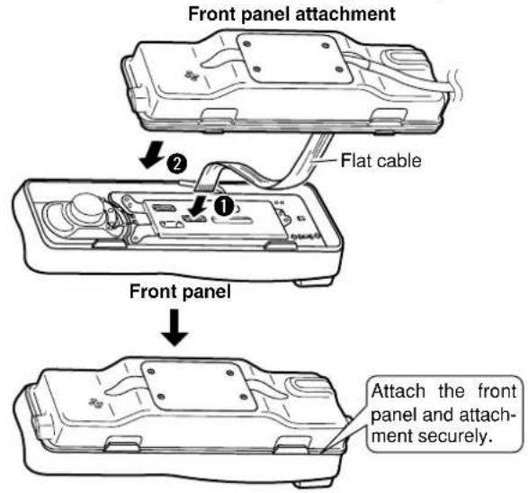
Use the screw removed from the circuit board in step ⑤ on the front page, to connect the cable lug. Rear plate Cable groove OPC-607/ OPC-608/ OPC-609 Front panel attachment② Connect the flat cable (1) as shown below, and then attach the front panel and the attachment (2).
- Ensure the flat cable is inserted correctly, and not upside down.
text_image
Front panel attachment Flat cable Front panel Attach the front panel and attach- ment securely.For the main body attachment:
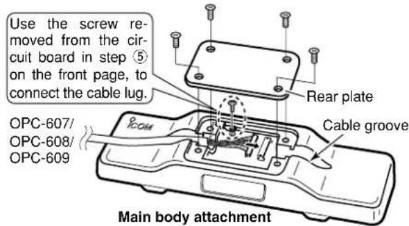
③Connect the optional OPC-607, OPC-608 or OPC-609 to the main body attachment as shown below.
After the cable connection, replace the removed rear plate.
- The optional cable can be inserted into either the left or right grooves as desired on the back of the attachment.
text_image
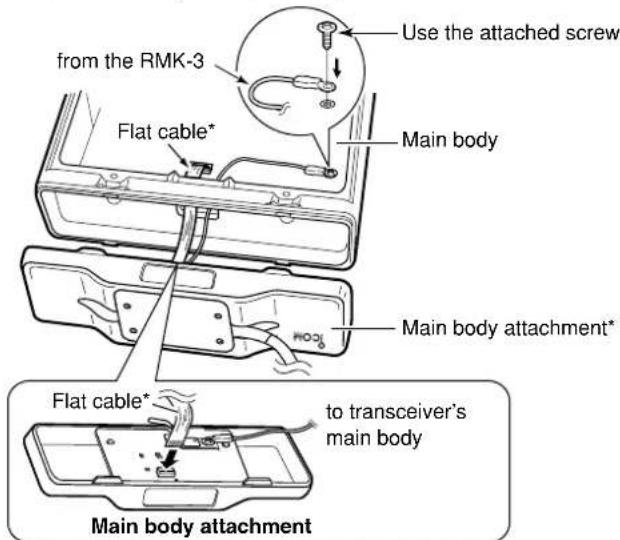
Use the screw removed from the circuit board in step ⑤ on the front page, to connect the cable lug. Rear plate Cable groove OPC-607/ OPC-608/ OPC-609 ICOM Main body attachment④ Connect the supplied flat cable* and ground cable (coming from the RMK-3) as shown below.
text_image
from the RMK-3 Use the attached screw Flat cable* Main body Main body attachment* Flat cable* to transceiver's main body Main body attachment*Ensure the flat cable and attachment are inserted/attached correctly, and not upside down.
⑤Replace the removed bottom cover and 4 screws, then reconnect the DC power cable.
■Mounting
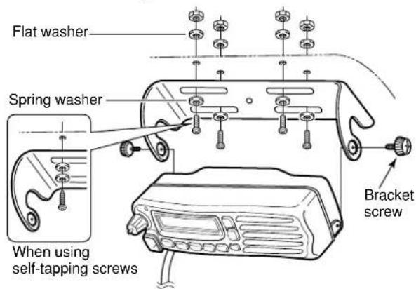
2 types of mounting styles are available— one is overhead mounting, and other one is on-board mounting.
Mount the front panel and the attachment securely with the 4 supplied screws to a thick surface which can support more than 1.5 kg. (Overhead mounting)
On-board mounting
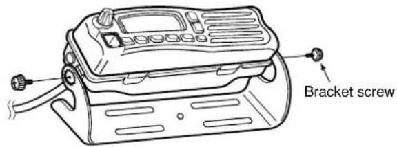
text_image
Bracket screwOverhead mounting