
IC-M1V - Modtager ICOM - Gratis brugsanvisning og manual
Find enhedens vejledning gratis IC-M1V ICOM i PDF-format.


Brugerspørgsmål om IC-M1V ICOM
0 spørgsmål om dette apparat. Besvar dem du kender, eller stil dit eget.
Stil et nyt spørgsmål om dette apparat
Download vejledningen til din Modtager i PDF-format gratis! Find din vejledning IC-M1V - ICOM og tag din elektroniske enhed tilbage i hånden. På denne side er alle dokumenter nødvendige for brugen af din enhed offentliggjort. IC-M1V af mærket ICOM.
BRUGSANVISNING IC-M1V ICOM

VHF MARINE TRANSCEIVER
IC-M1V
This device complies with Part 15 of the FCC rules. Operation is subject to the following two conditions: (1) This device may not cause harmful interference, and (2) this device must accept any interference received, including interference that may cause undesired operation.
Icom Inc.

natural_image
Black-and-white photo of a walk-in-wheeled radio device with antenna and control buttons (no visible text or symbols)FOREWORD
Thank you for purchasing this Icom product. The IC-M1V VHF MARINE TRANSCEIVER is designed and built with Icom's superior technology and craftsmanship. With proper care, this product should provide you with years of trouble-free operation.
IMPORTANT
READ ALL INSTRUCTIONS carefully and completely before using the transceiver.
SAVE THIS INSTRUCTION MANUAL— This instruction manual contains important operating instructions for the IC-M1V.
EXPLICIT DEFINITIONS
| WORD | DEFINITION |
| WARNING | Personal injury, fire hazard or electric shock may occur. |
| CAUTION | Equipment damage may occur. |
| NOTE | Recommended for optimum use. No risk of personal injury, fire or electric shock. |
CAUTION
⚠ WARNING! NEVER connect the transceiver to an AC outlet. This may pose a fire hazard or result in an electric shock.
⚠ WARNING! NEVER hold the transceiver so that the antenna is very close to, or touching exposed parts of the body, especially the face or eyes, while transmitting. The transceiver will perform best if the microphone is 5 to 10 cm (2 to 4 in) away from the lips, and the transceiver is vertical.
NEVER connect the transceiver to a power source other than the BP-215L. Such a connection will ruin the transceiver.
NEVER charge battery packs except in the methods described in this manual.
AVOID using or placing the transceiver in areas with temperatures below -20^ ( -4^ ) or above +60^ ( +140^ ).
AVOID the use of chemical agents such as benzine or alcohol when cleaning, as they may damage the transceiver surfaces.

BE CAREFUL! The transceiver rear panel will become hot when operating continuously for long periods.
BE CAREFUL! The IC-M1V employs waterproof construction, which corresponds to JIS waterproof specification, grade 7 (1 m/30 min.). However, once the transceiver has been dropped, waterproofing cannot be guaranteed due to the fact that the transceiver may be cracked, or the waterproof seal damaged, etc.
MAKE SURE the flexible antenna and battery pack are securely attached to the transceiver, and that the antenna and battery pack are dry before attachment. Exposing the inside of the transceiver to water will result in serious damage to the transceiver.
KEEP the transceiver at least 1 m (3.3 ft) away from the ship's navigation compass.
KEEP the transceiver out of the reach of children.
For U.S.A. only
CAUTION: Changes or modifications to this device, not expressly approved by Icom Inc., could void your authority to operate this device under FCC regulations.
IN CASE OF EMERGENCY
If your vessel requires assistance, contact other vessels and the Coast Guard by sending a distress call on channel 16;

TABLE OF CONTENTS
FOREWORD ...... i
IMPORTANT ...... i
EXPLICIT DEFINITIONS ...... i
CAUTION ....i
IN CASE OF EMERGENCY ...... ii
TABLE OF CONTENTS .... iii
1 OPERATING RULES.... 1
2 PANEL DESCRIPTION 2-5
■ Front panel 2
■ Function display 4
3 SUPPLIED ACCESSORIES AND ATTACHMENTS ..... 6
4 BASIC OPERATION 7-11
■ Channel selection .... 7
■ Receiving and transmitting 9
■ Lock function 10
■ Automatic backlighting 10
■ Optional voice scrambler operation 10
■ Call channel programming 11
5 SCAN OPERATIONS .... 12-13
■ Scan types 12
■ Setting tag channels 13
■ Starting a scan 13
6 DUALWATCH/TRI-WATCH 14
■ Description .... 14
■ Operation 14
7 CHANNEL COMMENT PROGRAMMING .... 15
■ About the channel comment 15
■ Channel comment programming .... 15
8 SET MODE 16-19
■ SET mode programming 16
■ SET mode items 16
9 BATTERY CHARGING 20-21
■ Caution 20
■ Battery charging 20
10 SPEAKER-MICROPHONE 22
■ Description 22
■ Attachment 22
11 TROUBLESHOOTING 23
12 CHANNEL LIST 24
13 QUICK REFERENCE....25
14 RECOMMENDATION 26
15 SPECIFICATIONS AND OPTIONS 27
■ Specifications 27
■ Options 27
OPERATING RULES
1
◇ PRIORITIES
① Read all rules and regulations pertaining to priorities, and keep an up-to-date copy handy. Safety and distress calls take priority over all others.
② You must monitor channel 16 when you are not operating on another channel.
③ False or fraudulent distress signals are prohibited and punishable by law.
◇ PRIVACY
① Information overheard, but not intended for you, cannot lawfully be used in any way.
② Indecent or profane language is prohibited.
◇ RADIO LICENSES
(1) SHIP STATION LICENSE
You must have a current radio station license before using the transceiver. It is unlawful to operate a ship station which is not licensed.
Inquire through your dealer or the appropriate government agency for a Ship-Radiotelephone license application. This government-issued license states the call sign which is your craft's identification for radio purposes.
(2) OPERATOR'S LICENSE
A Restricted Radiotelephone Operator Permit is the license most often held by small vessel radio operators when a radio is not required for safety purposes.
The Restricted Radiotelephone Operator Permit must be posted or kept with the operator. Only a licensed radio operator may operate a transceiver.
However, non-licensed individuals may talk over a transceiver if a licensed operator starts, supervises, ends the call and makes the necessary log entries.
Keep a copy of the current government rules and regulations handy.

2
PANEL DESCRIPTION
■ Panel description

① VOLUME CONTROL [VOL]
Turns power ON and adjusts the audio level. (p. 9)
② SQUELCH CONTROL [SQL]
Sets the squelch threshold level. (p. 9)
③ PTT SWITCH [PTT]
Transmits during push; receives during release. (p. 9)
④ MONITOR SWITCH [MONI]
→ Opens the squelch and monitors the operating channel while being pushed.
While turning power ON, enters the SET mode and is used to select the SET mode contents when pushed. (p. 16)
⑤ BATTERY PACK RELEASE BUTTON
- To remove the battery pack: Slide the battery release button upwards, then lift up the battery pack.
- To attach the battery pack: Mate the notched ends of the transceiver and the battery pack, and click the battery pack into place firmly. Ensure the battery that is properly attached.

natural_image
Technical line drawing of a mechanical component with internal cavities and a curved arrow indicating rotation (no text or symbols)PANEL DESCRIPTION
⑥ CHANNEL UP/DOWN SWITCHES [▲]/[▼]
→ Push either switch to change the operating channel. (pgs. 7–9)
→ Checks tag channels or changes scanning direction during scan. (p. 13)
→Push either switch to change the setting during set mode. (p. 16)
⑦ CHANNEL 16 SWITCH [16•9]
→ Selects channel 16 when pushed. (p. 7)
→ Selects the call channel when pushed for 2 sec. (p. 7)
→Enters call channel write mode when the call channel is selected, and this switch is pushed for 5 sec. (p. 11)
⑧ INTERNAL MICROPHONE (p. 9)
⑨ SPEAKER-MICROPHONE CONNECTOR [SP MIC]
Connects the optional speaker-microphone. (p. 22)
⑩ ANTENNA CONNECTOR
Connects the supplied antenna. (p. 6)
⑪ CHANNEL/WEATHER CHANNEL SWITCH [CH/WX•U/I/C]
→ Selects and changes the regular channels and weather channel when pushed momentarily. (p. 8)
▶ Selects one of 3 regular channels in sequence when pushed for 2 sec. (p. 8)
• U.S.A., International and Canadian channels are available for regular channels.
⑫ DUALWATCH/TRI-WATCH SWITCH [DW•TRI]
→ Starts dualwatch when pushed momentarily. (p. 14)
→ Starts tri-watch when pushed for 2 sec. (p. 14)
→ Stops dualwatch/tri-watch when either is activated.
(p. 14)
→Enters comment writing condition when pushed while pushing and holding [MONI]. (p. 15)
⑬ SCAN SWITCH [SCAN•TAG]
→ Starts and stops normal or priority scan when tag channels are programmed. (p. 13)
Sets the displayed channel as a tag (scanned) channel when pushed for 2 sec. (p. 13)
→While turning power ON, clears all tag channels in the selected regular channel group when pushed. (p. 13)
→ Activates an optional voice scrambler function while pushing [MONI]. (p. 10)
14 TRANSMIT POWER/LOCK SWITCH [H/L•LOCK]
→ Changes high and low power (1 W) when pushed. (p. 9)
• Some channels are set to low power only.
→While pushing [MONI], push this key to select extra low power (500 mW). (p. 9)
→ Changes the lock function ON and OFF when pushed for 2 sec. (p. 10)
15 INTERNAL SPEAKER
2 PANEL DESCRIPTION
■ Function display
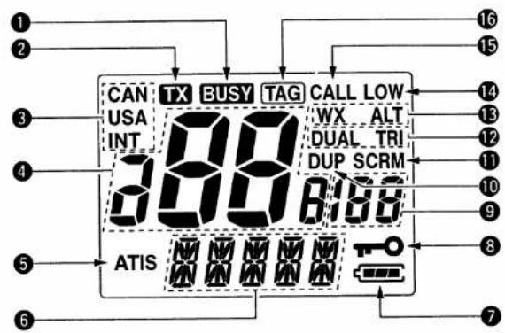
① BUSY INDICATOR (p. 9)
Appears while receiving a signal or while the squelch is open.
② TRANSMIT INDICATOR (p. 9)
Appears while transmitting.
③ CHANNEL GROUP INDICATORS (p. 8)
Appears "USA" when U.S.A.; "INT" when International; "CAN" when Canadian channel group is selected.
④ CHANNEL NUMBER READOUT
- Indicates the selected operating channel number. (pgs. 7, 8)
- In SET mode, indicates the selected condition. (pgs. 16–19)
⑤ ATIS INDICATOR
Appears while ATIS function is activated. (German version only)
⑥ COMMENT INDICATOR
- Indicates or scrolls operating channel comment, etc. (pgs. 7, 13, 15)
- In SET mode, indicates or scrolls the selected item. (pgs. 16–19)
PANEL DESCRIPTION
⑦ BATTERY INDICATOR
Indicates remaining battery power.
| Indication |  |  |  |  |
| Battery level | Full | Middle | Charging required | No battery |
⑧ LOCK INDICATOR (p. 10)
Appears while the lock function is activated.
⑨ SUB CHANNEL READOUT
- Indicates channel 16 during priority scan. (p. 13)
- Indicates channel 16 during dualwatch or tri-watch. (p. 14)
⑩ DUPLEX INDICATOR
Appears when a duplex channel is selected.
⑪ SCRAMBLER INDICATOR
Appears when the optional voice scrambler is activated. (p. 10)
⑫ DUALWATCH/TRI-WATCH INDICATORS (p. 14)
- "DUAL" blinks during dualwatch.
- "TRI" blinks during tri-watch.
⑬ WEATHER CHANNEL/WEATHER ALERT INDICATOR
(p. 8)
- "WX" appears when weather channel group is selected.
- "ALT" appears while the weather alert function is activated; blinks when alert tone is received.
⑭ LOW POWER INDICATOR (p. 9)
• Appears when low power is selected.
- Blinks when extra low power is selected.
⑮ CALL CHANNEL INDICATOR (p. 7)
Appears when a call channel is selected.
⑯ TAG CHANNEL INDICATOR (p. 13)
Appears when a tag channel is selected.
3
SUPPLIED ACCESSORIES AND ATTACHMENTS
◇ Supplied accessories
The following accessories are supplied: Qty.
① Flexible antenna (FA-S57V) ....1
② Battery pack (BP-215L) 1
③ Battery charger (AD-95) 1
④ AC adapter* (BC-122A/E*, BM-95V*) ....1
⑤ Handstrap ....1
⑥ Belt clip 1
⑦ Screws for the belt clip (M3 × 4) .....2
⑧ Screws for the AD-95 (M3.5 × 30)....2
*Depending on version
◇ Belt clip attachment
Attach the belt clip with the supplied screws. Conveniently attaches to your belt.

NEVER use the supplied screws without the belt clip, otherwise, the screw holes may be damaged and the transceiver might cease to be waterproof. Use the supplied screws only when attaching the belt clip.
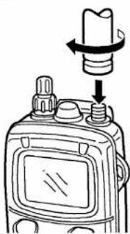
◇ Flexible antenna attachment
Insert the supplied antenna into the antenna connector and screw down the antenna as shown in the diagram at right.
CAUTION: Attach the supplied antenna securely for water-proofing.
CAUTION: Transmitting without an antenna may damage the transceiver.
◇ Handstrap attachment
Slide the handstrap through the loop on the side of the transceiver as illustrated at right.
Facilitates carrying.
natural_image
Illustration of a radio receiver with a rotating button and adjustment knob (no text or symbols)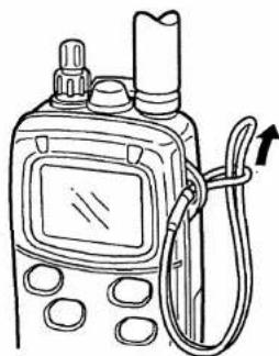
natural_image
Line drawing of a walkie-talkie with attached cable and sensor (no text or symbols)BASIC OPERATION
■ Channel selection
Channel 16
Channel 16 is the distress channel. It is used for establishing initial contact with another station and for emergency communications. Channel 16 is automatically monitored during both dualwatch and tri-watch. While standing by, you must monitor channel 16.
→ Push [16] to select channel 16.
→Push [CH/WX] to return to the condition before selecting channel 16, or push [▲]/[▼] to select operating channel.
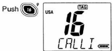
Scrolls the channel comment, "CALLING".
◇ Channel 9 (Call channels)
Channel 9 is the pleasure call channel. Each regular channel group has separate call channels. In addition, each call channel is monitored during tri-watch. The call channels can be programmed (p. 11) and are used to store your most often used channels in each group for quick recall.
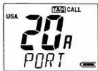
→ Push [16•9] for 2 sec. to select the call channel; of the selected channel group.
- The "CALL" indicator and call channel number appear.
• Each channel group may have an independent call channel after changing a call channel.
→Push [CH/WX] to return to the condition before selecting channel 9 (call channel), or push [▲]/[▼] to select operating channel.

for 2 sec.

Scrolls the channel comment, "CALLING".
4 BASIC OPERATION
◇ Weather channels
There are 10 weather channels. They are used for monitoring weather channels from the NOAA (National Oceanographic and Atmospheric Administration) broadcasts.
The IC-M1V can detect a weather alert tone on the selected weather channel while receiving in another channels, during standby on a regular channel, or while scanning. See the "SET mode items" on p. 17.
→ Push [CH/WX] once or twice to select the weather channel group.
→Push [▲]/[▼] to select weather channel.
→ Push [CH/WX] to return to the condition before selecting weather channel group.

Scrolls the channel comment, "162,550MHz".
◇ U.S.A., International and Canadian channels
There are 57 International, 61 U.S.A. and 57 Canadian channels. These channel groups may be specified for the operating area.
① Push [CH/WX] to select a regular channel.
- If a weather channel appears, push [CH/WX] again.
② Push [▲]/[▼] to select a channel.
- "DUP" appears for duplex channels.
③ To change the channel group, push [CH/WX•U/I/C] for 2 sec.
• U.S.A., International and Canadian channels can be selected in sequence.

flowchart
graph TD
    A["USA 21A CCG"] -->|Push for 2 sec.| B["U.S.A. channels"]
    B -->|U/I/C| C["CH/WX"]
    B -->|U/I/C| D["CAN"]
    C --> E["International channels"]
    D --> F["Canadian channels"]
    E --> G["TELEP"]
    F --> H["VTS"]
■ Receiving and transmitting
CAUTION: Transmitting without an antenna may damage the transceiver.
① Rotate [VOL] clockwise to turn power ON, then set to the 10 o'clock position.
- Turn [SQL] clockwise to mute any audio noise if necessary.
CAUTION: If the comment, "WET INSIDE", appears, turn the power OFF immediately, and contact your local dealer, or service center.
② Push [▲]/[▼] to select the desired channel.
- When receiving a signal, "BUSY" appears and audio is emitted from the speaker.
• Further adjustment of [VOL] may be necessary at this point. - Use the optional voice scrambler function for privacy. (p. 10)
③ Push [H/L] to select the output power if necessary.
- "LOW" appears when low power is selected.
- Choose low power to conserve battery power, choose high power for longer distance communications.
• Some channels are for low power only. - An extra low power, Low 2, is available for short distance communications. Push [H/L] while pushing [MONI] in such a case.
④ Push and hold [PTT] to transmit, then speak into the mic.
- "TX" appears.
- Channel 70 cannot be used for transmission (for GMDSS use).
NOTE: Simplex channels, 3, 21, 23, 61, 64, 81, 82 and 83 CANNOT be lawfully used by the general public in USA waters.
⑤ Release [PTT] to receive.
IMPORTANT: To maximize the readability of your transmitted signal (voice), pause a few sec. after pushing [PTT], hold the microphone 10 to 15 cm (4 to 6 inches) from your mouth and speak at a normal voice level.
The transceiver has a power save function to conserve the battery power which can be turned OFF. The power save function activates automatically when no signal is received for 5 sec. See page 18 for details.
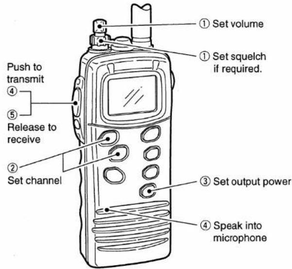
4 BASIC OPERATION
■ Lock function
This function electronically locks all keys and switches to prevent accidental frequency changes and function access.
→ Push [H/L•LOCK] for 2 sec. to turn the lock function ON and OFF.
• Only [PTT], [H/L] and [MONI] are functional.
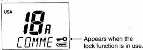
■ Automatic backlighting
This function is convenient for nighttime operation. The automatic backlighting can be activated in SET mode. (p. 18)
→ Push any key except for [PTT] to turn the backlighting ON.
• The backlighting is automatically turned OFF 5 sec. after operation.
- Push [MONI] to turn the backlighting ON without changing the operating condition.
■ Optional voice scrambler operation
◇ Activating the scrambler
The optional voice scrambler provides private communications. In order to receive or send scrambled transmissions, you must first activate the scrambler function. To activate the function, either an optional UT-98 or UT-112 is necessary. Ask your dealer for details.
① Select an operating channel except channel 16 or weather channels.
② Push [SCN] while pushing and holding [MONI].
- "SCRM" appears.
③ To turn the scrambler function OFF, repeat step ②.
- "SCRM" disappears.

Appears when the voice scrambler function is in use.
◇ Programming scramble codes
There are 128 codes (00 to 127) available with UT-98 or 32 codes (01 to 32) available with UT-112 for programming. In order to understand one another, all transceivers in your group must have the same scramble code, as well as the same scrambler unit. See page 19 for scrambling code setting details.
RECOMMENDATION: Use the optional speaker-microphone during voice scrambling operation for much clearer audio readability.
■ Call channel programming
The call channel key is used to select channel 9, however, you can program your most often-used channels in each channel group for quick recall.
① Push [CH/WX•U/I/C] for 2 sec. several times to select the desired channel group (USA, INT, CAN) to be programmed.
② Push [16•9] for 2 sec. to select the call channel of the selected channel group.
- "CALL" and call channel number appear.
③ Push [16•9] again for 5 sec. (until long beep changes to 2 short beeps) to enter call channel programming condition.
- Call channel number and channel group to be programmed flashes.


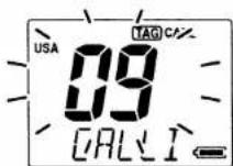
④ Push [▲]/[▼] to select the desired channel.

⑤ Push [16•9] to program the displayed channel as the call channel.
• The call channel number and channel group stop flashing.

5 SCAN OPERATIONS
■ Scan types
Scanning is an efficient way to locate signals quickly over a wide frequency range. The transceiver has priority scan and normal scan.
In addition, weather alert and an automatic scan start function is available for standby convenience. (pgs. 17, 18)
PRIORITY SCAN
flowchart
graph TD
    CH16["CH 16"] --> CH01["CH 01"]
    CH16 --> CH02["CH 02"]
    CH16 --> CH03["CH 03"]
    CH16 --> CH04["CH 04"]
    CH16 --> CH05["CH 05"]
    CH16 --> WX*[WX*]
    CH01 --> WX*
    CH02 --> WX*
    CH03 --> WX*
    CH04 --> WX*
    CH05 --> WX*
    style CH16 fill:#f9f,stroke:#333
    style WX* stroke-dasharray: 5 5
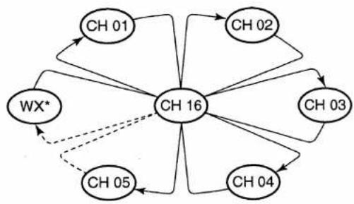
Priority scan searches through all tag channels in sequence while monitoring channel 16. When a signal is detected on channel 16, scan pauses until the signal disappears; when a signal is detected on a channel other than channel 16, scan becomes dualwatch until the signal disappears.
Set the tag channels (scanned channel) before scanning. Clear the tag channels which inconveniently stop scanning, such as digital communication use.
Choose priority or normal scan in SET mode. (p. 17)
NORMAL SCAN

flowchart
graph TD
    WX* --> CH01
    CH01 --> CH02
    CH02 --> CH03
    CH03 --> CH04
    CH04 --> CH05
    CH05 -.-> WX*
    CH01 -.-> CH05
*Previously selected weather channel when weather alert function is ON.
Normal scan, like priority scan, searches through all tag channels in sequence. However, unlike priority scan, channel 16 is not checked unless channel 16 is set as a tag channel.
■ Setting tag channels
For more efficient scanning, add desired channels as tag channels or clear tag channels for unwanted channels. Channels, set as non-tag channels will be skipped during scanning. Tag channels can be assigned to each channel group (USA, INT, CAN) independently.
① Select the desired channel group (USA, INT, CAN) by pushing [CH/WX•U/I/C] for 2 sec., if desired.
② Select the desired channel to set as a tag channel.
③ Push [SCN•TAG] for 2 sec., to set the displayed channel as a tag channel.
- "TAG" appears in the function display.
④ To cancel the tag channel setting, push [SCN•TAG] for 2 sec.
- "TAG" disappears.
- Clearing all tag channels in the selected channel group
Turn power ON while pushing and holding [SCN•TAG] to clear all tag channels in the channel group.
■ Starting a scan
Set scan type, weather alert function, scan resume timer and auto scan function in advance, using SET mode. (pgs. 17, 18)
① Select the desired channel group (USA, CAN, INT) by pushing [CH/WX•U/I/C] for 2 sec., if desired.
- When the weather alert function is in use, select the desired weather channel with [CH/WX] and the channel selector.
② Push [SCN] to start priority or normal scan.
• The comment indicator flashes "SCAN".
- The sub channel readout indicates "16" during priority scan.
- When a signal is received, scan pauses until the signal disappears or resumes after pausing 5 sec. according to SET mode setting. (Channel 16 is still monitored during priority scan.)
- Push [▲]/[▼] to check the scanning tag channels, to change the scanning direction or resume the scan manually.
③ To stop the scan, push [SCN].
- "SCAN" disappears.
- Pushing [PTT], [16•9], [CH/WX] or [DW•TRI] also stops the scan.

flowchart
graph LR
    A["Start: USA 88A COMME"] -->|Push TAG| B["Scan starts: USA 88A DUP = SCAN"]
    B --> C["Scan pauses when receiving a signal and audio is emitted."]
    C -->|Push to stop the scan.| D["End: USA 88A DUP = SCAN"]
6
DUAL WATCH/TRI-WATCH
■ Description
Dualwatch monitors channel 16 while you are receiving another channel; tri-watch monitors channel 16 and the call channel while receiving another channel.
DUALWATCH/TRI-WATCH SIMULATION

Dualwatch

flowchart
graph TD
    A["16"] --> B["89"]
    B --> C["88_A"]
    C --> A
    style A fill:#f9f,stroke:#333
    style B fill:#ccf,stroke:#333
    style C fill:#cfc,stroke:#333
    note right of B: Call channel
Tri-watch
- If a signal is received on channel 16, dualwatch/tri-watch pauses on channel 16 until the signal disappears.
- If a signal is received on the call channel during tri-watch, tri-watch becomes dualwatch until the signal disappears.
- To transmit on the selected channel during dualwatch/tri-watch, push and hold [PTT].
- If no signal is received, the transceiver enters the power saving condition for 0.5 sec. after checking the operating channel every cycle.
Operation
① Select the desired operating channel.
② Push [DW•TRI] momentarily to start dualwatch; push [DW•TRI] for 2 sec. to start tri-watch.
- "DUAL" flashes during dualwatch; "TRI" flashes during tri-watch.
- Beep tone sounds when a signal is received on channel 16.
- Tri-watch becomes dualwatch when receiving a signal on the call channel.
③ To cancel dualwatch/tri-watch, push [DW•TRI] again.
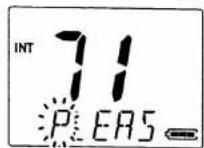
[Example]: Operating tri-watch on INT channel 07.
Push for 1 sec.

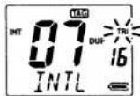
Tri-watch starts.

Signal is received on call channel.

Signal received on channel 16 takes priority.

Tri-watch resumes after the signal disappears.
CHANNEL COMMENT PROGRAMMING
■ About the channel comment
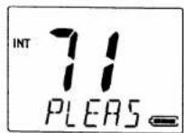
The IC-M1V has a capability to assign up to 10-character channel comments for each operating channel, including the weather channel. This provides easy recognition of channel usage, or station names, etc.
When shipped from the factory, the IC-M1V is programmed with default comments for each VHF marine channel. These defaults can be overwritten if desired.
◇ Available characters
| --(=) | f(+) | --(-) | ※ (*) | /'(I) | (.) | (space) | ^(0) | I(1) | ^(2) |
| ^(3) | 4^(4) | 5^(5) | ^(6) | 7^(7) | ^(8) | ^(9) | ^(A) | ^(B) | ^(C) |
| ^(D) | E^(E) | F^(F) | ^(G) | H^(H) | I^(I) | J^(J) | K^(K) | L^(L) | M^(M) |
| N^(N) | O^(O) | P^(P) | Q^(Q) | R^(R) | S^(S) | T^(T) | U^(U) | V^(V) | W^(W) |
| X^(X) | Y^(Y) | Z^(Z) | ^(a) | b^(b) | c^(c) | d^(d) | E^(e) | F^(f) | G^(g) |
| h^(h) | (i) | J^(j) | K^(k) | I^(l) | m^(m) | n^(n) | O^(o) | P^(p) | Q^(q) |
| r^-(r) | S^(s) | t^-(t) | U^(u) | V^(v) | w^(w) | X^(x) | Y^(y) | Z^(z) |
■ Channel comment programming
① Push [▲]/[▼] to select a channel to program.
- Push [CH/WX•U/I/C] for 2 sec. to select a channel group, if necessary.
② While pushing [MONI], push [DW].
• The 1st character of the currently programmed comment flashes.
③ Push [▲]/[▼] to select a character.
④ Push [SCN] to move to the right; then push [▲]/[▼] to select a character.
- Pushing [H/L], moves to left
⑤ Continue until the desired characters have been selected, then push [DW] to return to normal operation.


8
SET MODE
■ SET mode programming
SET mode is used to change the condition of 10 of the transceiver's functions: beep tone function, weather alert function, scan type (normal/priority), scan resume timer, auto scan function, automatic backlighting, power save function, self check function, voice scrambler type and scrambling code.
When no optional voice scrambler unit is installed, voice scrambler type and scrambling code cannot be set. (will not be displayed)
① Turn power OFF.
② While pushing [MONI], turn power ON and continue pushing [MONI] until a beep is emitted.
• After beep emission, release [MONI].
- Set mode item at comment indicator and condition at channel number readout are displayed.
④ Push [MONI] to select the desired item, if necessary.
⑤ Push [▲]/[▼] to select the desired condition of the item.
⑥ To exit SET mode, push [16].
- Turning power OFF, then ON again also exits SET mode.

flowchart
graph TD
    A["BEEP"] --> B["WX ALERT"]
    B --> C["SCAN TYPE"]
    C --> D["SCAN TIMER"]
    D --> E["AUTO SCAN"]
    E --> F["BACKLIGHT"]
    F --> G["POWER SAVE"]
    G --> H["SELF CHECK"]
    H --> I["Self check function"]
    J["Scrambling code"] --> K["Scram unit selection"]
    L["Scan resume timer"] --> M["Scan type"]
    N["Push"] --> O["Power save"]
    P["Auto scan"] --> Q["Automatic backlighting"]
    R["Beep tone"] --> A
    S["Weather alert"] --> B
    T["Push"] --> U["Power save"]
■ SET mode items
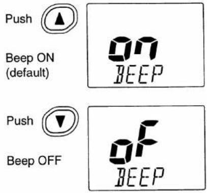
◇ Beep tone "BEEP"
You can select silent operation by turning the beep tones OFF, or you can have confirmation beeps sound at the push of a switch, by turning the beep tones ON. The beep tone volume is linked with [VOL].
◇ Weather alert function
"WX ALERT"
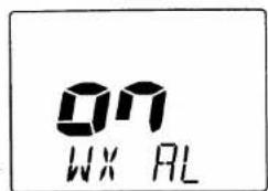
An NOAA broadcast station transmits a weather alert tone before any important weather information. When the weather alert function is turned ON, the transceiver detects the alert, then flashes the "ALT" indicator until the transceiver is operated. The previously selected (used) weather channel is checked any time during standby, or while scanning, when the power save function is activated.
- "ALT" appears when the function is set ON.
Push

Weather alert ON
Push

Weather alert OFF (default)

Scrolls the channel comment, "WX ALERT".
◇ Scan type selection
"SCAN TYPE"
The transceiver has 2 scan types: normal scan and priority scan. Normal scan searches all tag channels in the selected channel group. Priority scan searches all tag channels in sequence while monitoring channel 16.
Push

Priority scan selection

Push

Normal scan selection (default)

Scrolls the channel comment, "SCAN TYPE".
◇ Scan resume timer
"SCAN TIMER"
The scan resume timer can be selected as a pause (OFF) or timer scan (ON). When OFF is selected, the scan pauses until the signal disappears. When ON is selected, the scan pauses 5 sec. and resumes, even if a signal is being received on channels, other than channel 16.
Push

Scan resume timer ON
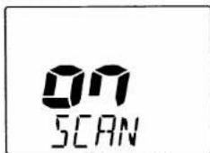
Push

Scan resume timer OFF (default)

Scrolls the channel comment, "SCAN TIMER".
8 SET MODE
◇ Auto scan function
"AUTO SCAN"
While in standby, this function automatically starts the desired scan (normal or priority scan) 30 sec. after operation.
- The comment indicator indicates "SCAN" while scanning.
The transceiver has a power save function, but it does not activate when the auto scan function is in use.
◇ Automatic backlighting
"BACKLIGHT"
This function is convenient for nighttime operation. The automatic backlighting turns the backlighting ON when pushing any key except for [PTT].
• The backlighting automatically turns OFF 5 sec. after operation.
- Push [MONI] to turn the backlighting ON without changing the operating condition.
- The backlight comes ON when entering SET mode, regardless of this setting.
Power save function
"POWER SAVE"
The power save function reduces current drain by deactivating the receiver circuit for fixed intervals.
The power save function does not activate when the auto scan function is in use.


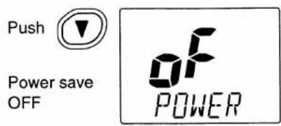
Scrolls the channel comment, "AUTO SCAN".
Scrolls the channel comment, "BACKLIGHT".
Scrolls the channel comment, "POWER SAVE".
◇ Self check function
"SELF CHECK"
The self check function checks transceiver conditions by itself, and informs you in case a problem is found. The following items are checked after the power is turned ON, then, switches to operation mode.
- PLL lock (both transmit and receive)
- Temperature
• Connected battery voltage - Water intrusion
Push

Self check function ON

Push

Self check function OFF (default)
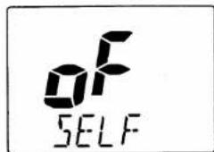
comment, "SELF CHECK".
◇ Scrambler unit selection
"SCRAM UNIT"
This item appears only when a voice scrambler unit is installed.
Selects installed voice scrambler unit. Otherwise, the voice scrambler function cannot be operated.
Push

Selects UT-98 (default)

Push

Selects UT-112

Scrolls the channel comment, "SCRAM UNIT".
◇ Scrambler code
"SCRAM CODE"
There are 128 codes (00 to 127) available with UT-98, or 32 codes (01 to 32) available with UT-112, for programming. In order to understand one another, all transceivers in your group must have the same unit* and scramble code.
*Different scrambling systems are used between UT-98 and UT-112, therefore the same scrambler unit must be used in your group.
Scrambling code 00 (default)
*01 min. when UT-112 is installed.

Scrambling code 127*
*32 max. when UT-112 is installed.
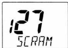
Scrolls the channel comment, "SCRAM CODE".

9
BATTERY CHARGING
■ Caution
NEVER incinerate used battery packs. Internal battery gas may cause an explosion.
NEVER immerse the battery pack in water. If the battery pack becomes wet, be sure to wipe it dry immediately (particularly the battery terminals) BEFORE attaching it to the transceiver. Otherwise, the terminals will become corroded, or cause connection failure, etc.
NEVER short the terminals of the battery pack. Also, current may flow into nearby metal objects, such as a necklace, etc. Therefore, be careful when carrying with, or placing near metal objects, carrying in handbags, etc.
AVOID leaving the battery pack in a fully charged, or completely discharged condition for long time. It causes shorter battery life. In case of leaving the battery pack unused for a long time, it must be kept safely after discharge, or use the battery until the battery indicator shows the middle level, then remove it from the transceiver.
If your battery pack seems to have no capacity even after being charged, completely discharge it by leaving the power ON overnight. Then, fully charge the battery pack again. If the battery pack still does not retain a charge (or very little), a new battery pack must be purchased.
■ Battery charging
Prior to using the transceiver for the first time, the battery pack must be fully charged for optimum life and operation.

CAUTION: To avoid damage to the transceiver, turn it OFF while charging.
- Recommended temperature range for charging: +10°C to +40°C (+50°F to +104°F)
- Use the supplied charger (AD-95) only. NEVER use another manufacturer's charger.
- An optional cable OPC-515L (for 13.8 V power source) or CP-17L (for 12 V cigarette lighter socket) can be used instead of the AC adapters of the supplied charger.
Recommendation:
Charge the supplied battery pack for a maximum of up to 10 hours. Li-Ion batteries are different from Ni-Cd batteries in that it is not necessary to completely charge and discharge them to prolong the battery life. Therefore, charge the battery in intervals, and not for extended periods is recommended.
BATTERY CHARGER
9
◇ AD-95 installations
- To a desktop

- For convenience:

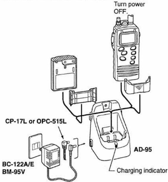
◇ Charging
① Connect the AC adapter (BC-122A/E, BM-95V) or optional cable (CP-17L or OPC-515L) as shown below.
② Insert the battery pack with/without the transceiver into the charger.
• The charge indicator light shows green.
③ Charge the battery pack for approx. 9–10 hours, depending on the remaining power condition.

10 SPEAKER-MICROPHONE
■ Descriptions

NEVER immerse the connector in water. If the connector becomes wet, be sure to dry BEFORE attaching it to the transceiver.
NOTE: The microphone is located at the top of the speaker-microphone, as shown in the diagram above. To maximize the readability of your transmitted signal (voice), hold the microphone approx. 2.5 cm (1 inch) from your mouth, and speak in a normal voice level.
■ Attachment
Insert the connector of the speaker-microphone into the [SP MIC] connector on the transceiver and rotate (screw) the connector cover as shown in the diagram below.

CAUTION: Attach the speaker-microphone's connector securely to prevent accidental dropping, or water intrusion in the connector.
IMPORTANT: KEEP the [SP MIC] jack cover attached (transceiver) when the speaker-microphone is not in use. Water will not get into the transceiver even if the cover is not attached, however, the terminals (pins) will become rusty, or the transceiver will function abnormally if the connector has become wet.
TROUBLESHOOTING
| PROBLEM | POSSIBLE CAUSE | SOLUTION | REF |
| No power comes ON. | The battery is exhausted.Bad connection of the battery pack. | Recharge the battery pack.Check the connection to the transceiver. | p. 21p. 2 |
| No sound comes from the speaker | Squelch level is too deep.[VOL] level is too low. | Set squelch to the threshold point.Set [VOL] to a suitable level. | p. 9p. 9 |
| Transmitting is impossible, or high power cannot be selected. | Some channels are for low power or receive only.The battery is exhausted.The output power is set to low or extra low. | Change channels.Recharge the battery pack.Push [H/L] to select high power. | p. 7p. 21p. 9 |
| The displayed channel cannot be changed. | Lock function is activated. | Push [H/L•LOCK] for 2 sec. to cancel the lock function. | p. 10 |
| Scan does not start. | “TAG” channel is not programmed. | Set the desired channels as “TAG” channels. | p. 13 |
| Scan starts automatically. | Auto scan function is activated. | Cancel the auto scan function in SET mode. | p. 18 |
| No beep sounds. | Beep tone is turned OFF. | Turn the beep tone ON in SET mode. | p. 16 |
| Receive signal cannot be understood. | Optional voice scrambler is turned OFF.Scramble code is not set correctly. | Turn the optional voice scrambler ON.Reset the scramble code. | p. 10p. 19 |

12 CHANNEL LIST
| Channel Number | Frequency (MHz) | |||
| USA | INT | CAN | Transmit | Receive |
| 01 | 01 | 156.050 | 160.650 | |
| 01A | 156.050 | 156.050 | ||
| 02 | 02 | 156.100 | 160.700 | |
| 03 | 03 | 156.150 | 160.750 | |
| 03A | 156.150 | 156.150 | ||
| 04 | 156.200 | 160.800 | ||
| 04A | 156.200 | 156.200 | ||
| 05 | 156.250 | 160.850 | ||
| 05A | 05A | 156.250 | 156.250 | |
| 06 | 06 | 06 | 156.300 | 156.300 |
| 07 | 156.350 | 160.950 | ||
| 07A | 07A | 156.350 | 156.350 | |
| 08 | 08 | 08 | 156.400 | 156.400 |
| 09 | 09 | 09 | 156.450 | 156.450 |
| 10 | 10 | 10 | 156.500 | 156.500 |
| 11 | 11 | 11 | 156.550 | 156.550 |
| 12 | 12 | 12 | 156.600 | 156.600 |
| 13^** | 13 | 13^** | 156.650 | 156.650 |
| 14 | 14 | 14 | 156.700 | 156.700 |
| 15^** | 15^** | 15^** | 156.750 | 156.750 |
| 16 | 16 | 16 | 156.800 | 156.800 |
| 17^** | 17 | 17^** | 156.850 | 156.850 |
| 18 | 156.900 | 161.500 | ||
| 18A | 18A | 156.900 | 156.900 | |
| 19 | 156.950 | 161.550 | ||
| 19A | 19A | 156.950 | 156.950 | |
| Channel Number | Frequency (MHz) | |||
| USA | INT | CAN | Transmit | Receive |
| 20 | 20 | 20" | 157.000 | 161.600 |
| 20A | 157.000 | 157.000 | ||
| 21 | 21 | 157.050 | 161.650 | |
| 21A | 21A | 157.050 | 157.050 | |
| 21b | Rx only | 161.650 | ||
| 22 | 157.100 | 161.700 | ||
| 22A | 22A | 157.100 | 157.100 | |
| 23 | 23 | 157.150 | 161.750 | |
| 23A | 157.150 | 157.150 | ||
| 24 | 24 | 24 | 157.200 | 161.800 |
| 25 | 25 | 25 | 157.250 | 161.850 |
| 25b | Rx only | 161.850 | ||
| 26 | 26 | 26 | 157.300 | 161.900 |
| 27 | 27 | 27 | 157.350 | 161.950 |
| 28 | 28 | 28 | 157.400 | 162.000 |
| 28b | Rx only | 162.000 | ||
| 60 | 60 | 156.025 | 160.625 | |
| 61 | 156.075 | 160.675 | ||
| 61A | 61A | 156.075 | 156.075 | |
| 62 | 156.125 | 160.725 | ||
| 62A | 156.125 | 156.125 | ||
| 63 | 156.175 | 160.775 | ||
| 63A | 156.175 | 156.175 | ||
| 64 | 64 | 156.225 | 160.825 | |
| 64A | 64A | 156.225 | 156.225 | |
| 65 | 156.275 | 160.875 | ||
| Channel Number | Frequency (MHz) | |||
| USA | INT | CAN | Transmit | Receive |
| 65A | 65A | 65A | 156.275 | 156.275 |
| 66 | 156.325 | 160.925 | ||
| 66A | 66A | 66A^*1 | 156.325 | 156.325 |
| 67^*1 | 67 | 67 | 156.375 | 156.375 |
| 68 | 68 | 68 | 156.425 | 156.425 |
| 69 | 69 | 69 | 156.475 | 156.475 |
| 70^*2 | 70^*2 | 70^*2 | 156.525 | 156.525 |
| 71 | 71 | 71 | 156.575 | 156.575 |
| 72 | 72 | 72 | 156.625 | 156.625 |
| 73 | 73 | 73 | 156.675 | 156.675 |
| 74 | 74 | 74 | 156.725 | 156.725 |
| 77^*1 | 77 | 77^*1 | 156.875 | 156.875 |
| 78 | 156.925 | 161.525 | ||
| 78A | 78A | 156.925 | 156.925 | |
| 79 | 156.975 | 161.575 | ||
| 79A | 79A | 156.975 | 156.975 | |
| 80 | 157.025 | 161.625 | ||
| 80A | 80A | 157.025 | 157.025 | |
| 81 | 157.075 | 161.675 | ||
| 81A | 81A | 157.075 | 157.075 | |
| 82 | 157.125 | 161.725 | ||
| 82A | 82A | 157.125 | 157.125 | |
| 83 | 83 | 157.175 | 161.775 | |
| 83A | 83A | 157.175 | 157.175 | |
| 83b | Rx only | 161.775 | ||
| 84 | 84 | 84 | 157.225 | 161.825 |
| Channel Number | Frequency (MHz) | |||
| USA | INT | CAN | Transmit | Receive |
| 84A | 157.225 | 157.225 | ||
| 85 | 85 | 85 | 157.275 | 161.875 |
| 85A | 157.275 | 157.275 | ||
| 86 | 86 | 86 | 157.325 | 161.925 |
| 86A | 157.325 | 157.325 | ||
| 87 | 87 | 87 | 157.375 | 161.975 |
| 87A | 157.375 | 157.375 | ||
| 88 | 88 | 88 | 157.425 | 162.025 |
| 88A | 157.425 | 157.425 | ||
| WX channel | Frequency (MHz) | |
| Transmit | Receive | |
| 1 | Rx only | 162.550 |
| 2 | Rx only | 162.400 |
| 3 | Rx only | 162.475 |
| 4 | Rx only | 162.425 |
| 5 | Rx only | 162.450 |
| 6 | Rx only | 162.500 |
| 7 | Rx only | 162.525 |
| 8 | Rx only | 161.650 |
| 9 | Rx only | 161.775 |
| 10 | Rx only | 163.275 |
*1Low power only.
*2Receive only.
NOTE: Simplex channels, 3, 21, 23, 61, 64, 81, 82 and 83 CAN-NOT be lawfully used by the general public in USA waters.
QUICK REFERENCE 13

Important operating instructions are summed up in this and the following page for your simple reference.
By cutting along the line and folding on the dotted line, it will become a card sized operating guide which can easily be carried in a card case or wallet, etc.

flowchart
graph LR
    A["① Cut"] --> B["② Fold"]
    B --> C["③ Complete"]
■ CHANNEL SELECTION (pgs. 7, 8)
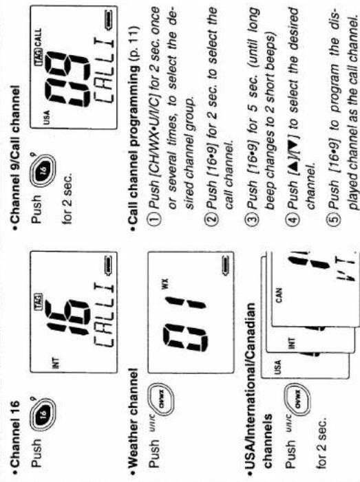


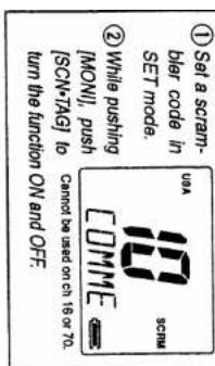
![VOICE SCRAMBER (p. 10) ① While pushing [MONI], turn power ON. 33EP 4 Push [16*·C] to return to regular op- ranging mode. ③ Push (▲/▼) to select the desired condition. for set to pgs 16-19 for set mode item. ④ Push [16*·C] to return to regular op- ranging mode. ⑤ Push (▲/▼) to select the desired condition. for set to pgs 16-19 for set mode item. ② Push [MOMI] gain to select an item. Rate for pgs 16-19 for set MODE item.](/content/2026/05/862930/images/24f3522a2060cc0352d5af6664380aa3e1f60d2cce90ec069b499a1492259662.jpg)
![① Push (▲/▼) to select the desired channel. ② For dual watch, push [DW•TRI]. For fit-watch, push [DW•TRI] for 1 sec. ③ Push (▲/▼) to select the desired channel. ④ Push (▲/▼) to select the desired channel. ⑤ Push. [SCN•TAG] for 1 sec. to change the setting ON and OFF. WEATHER ALERT (p.8) ① Turn the weather alert item in the SET mode ON. ② Select WX channel, or start scanning. ■ DUALWATCH/TRI-WATCH (p.14) ■ SCAN (p.13) Push [SCN•TAG] to start/stop scanning. ■ TAK CHANNELS (p.13)](/content/2026/05/862930/images/1ee576ca57b499d5542a49180d3effc9c9e0d0e767b09bf9455bfd550feebc00.jpg)

![■ LOCK FUNCTION (p. 10) ① Push [▲]/[▲] to select the desired channel. ② Push [Dw•TFL], while pushing [MONI]. ③ Push [▼]/[▲] to select the desired characters. ④ Push [SCN•TAG] to move to right. [H•LOCK] to move to left. ⑤ Push [DW•TRI] to return to normal operating mode.](/content/2026/05/862930/images/7e29678685d8840f590bdb84fa39e06aa51afbd860273cfa779326b1dd6d5f47.jpg)

14 RECOMMENDATION
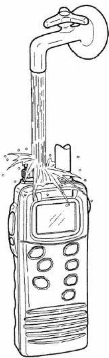
CLEAN THE TRANSCEIVER THOR- OUGHLY WITH FRESH WATER after exposure to salt water.
Otherwise, the transceiver's keys, switches and controllers may become inoperable due to salt crystallization.
natural_image
Line drawing of a portable radio device emitting sound waves from a pipe (no text or symbols)SPECIFICATIONS AND OPTIONS
Specifications
•GENERAL
• Frequency coverage
: Transmit 156–157.5 MHz
Receive 156–163 MHz
•Mode
- Channel spacing
• Current drain (at 7.4 V)
: FM (16K0G3E)
: 25 kHz
: TX at 5 W 1.5 A max.
Max.audio 200 mA max.
Power saved 20 mA typ.
•Power supply requirement
• Frequency stability
• Dimensions (with BP-215L) (Projections not included)
• Weight (with BP-215L)
: lcom battery pack; BP-215L
: ±10 ppm (-20°C to +60°C; -4°F to +140°F)
: 52.5(W)×129(H)×30(D) mm
2^1/16(W) × 5^3/32(H) × 1^3/16(D) in
: 280g (9.9 oz)
•TRANSMITTER
- Output power
- Modulation system
•Max. frequency deviation - Spurious emissions
: 5 W, 1 W and 0.5 W
: Variable reactance frequency modulation
: ±5.0 kHz
: Less than -65 dB
- RECEIVER
- Spurious response rejection ratio: 70 dB typical
-Receive system
• Sensitivity (12 dB SINAD)
•Squelch sensitivity
• Intermodulation rejection ratio
- Adjacent channel selectivity
•Audio output power
: Double conversion superheterodyne
: Less than 0.35 μV
: Less than 0.35 μV (at threshold)
: 70 dB typical
: 70 dB typical
: 70 dB typical
: 350 mW typical at 10% distortion
with an 8 Ω load
All stated specifications are subject to change without notice or obligations.
Options
• AD-95 BATTERY CHARGER + BC-122A/E/BM-95V AC ADAPTER
Used for regular charging of battery pack. The same as supplied with the transceiver. Charging time: approx. 9–10 hours
- BC-119N DESKTOP CHARGER + AD-102 DESKTOP CHARGER ADAPTER For rapid charging of battery pack. An AC adapter may supplied with the charger. Charging time: approx. 1.5–2 hours
- BC-121N MULTI-CHARGER + AD-102 DESKTOP CHARGER ADAPTER (6 pcs.) For rapid charging of up to 6 batteries (six AD-102's are required) simultaneously. Charging time: approx. 1.5–2 hours
•BP-215L BATTERY PACK
Long life, Li-ion battery pack allowing 15–16 hrs.* operation. The same as supplied with the transceiver. 7.4 V/1800 mAh.
*Tx:Rx:Stand-by=5:5:90
•CP-17L CIGARETTE LIGHTER CABLE
Connects to a ship's or vehicle's cigarette lighter socket (12 V) for use with the AD-95.
•FA-S57V FLEXIBLE ANTENNA
Same as supplied with the transceiver.
•HM-125 SPEAKER-MICROPHONE
Full-sized waterproof (JIS grade 7; 1m/30 min.) speaker-microphone including alligator type clip to attach to your shirt or collar, etc.
•OPC-515L DC POWER CABLE
Used for charging a battery pack via an AD-95 with external power supply.
•UT-98 VOICE SCRAMBLER UNIT
Ensures private communication. 128 scrambling codes are available. The scrambling system is not compatible with UT-112. Not available in some countries. Version 02 (#02) only can be used with the IC-M1V/M1EURO V (version 01 not compatible).
•UT-112 VOICE SCRAMBLER UNIT
Ensures private communication. 32 scrambling codes are available. The scrambling system is not compatible with UT-98. Not available in some countries.
Count on us!

natural_image
Close-up of a dark textured fabric with no visible text, symbols, or markingsA-5626H-1EX-④
Printed in Japan
© 1999-2002 Icom Inc.
Icom Inc.
1-1-32 Kamiminami, Hirano-ku, Osaka 547-0003 Japan

- IC-M1V
- FOREWORD
- IMPORTANT
- CAUTION
- IN CASE OF EMERGENCY
- TABLE OF CONTENTS
- OPERATING RULES
- 1
- ◇ PRIORITIES
- ◇ PRIVACY
- ◇ RADIO LICENSES
- SHIP STATION LICENSE
- OPERATOR'S LICENSE
- 2
- PANEL DESCRIPTION
- ■ Panel description
- ⑥ CHANNEL UP/DOWN SWITCHES [▲]/[▼]
- ⑦ CHANNEL 16 SWITCH [16•9]
- ⑧ INTERNAL MICROPHONE (p. 9)
- ⑨ SPEAKER-MICROPHONE CONNECTOR [SP MIC]
- ⑩ ANTENNA CONNECTOR
- ⑪ CHANNEL/WEATHER CHANNEL SWITCH [CH/WX•U/I/C]
- ⑫ DUALWATCH/TRI-WATCH SWITCH [DW•TRI]
- ⑬ SCAN SWITCH [SCAN•TAG]
- TRANSMIT POWER/LOCK SWITCH [H/L•LOCK]
- INTERNAL SPEAKER
- PANEL DESCRIPTION
- ■ Function display
- ⑦ BATTERY INDICATOR
- ⑧ LOCK INDICATOR (p. 10)
- ⑨ SUB CHANNEL READOUT
- ⑩ DUPLEX INDICATOR
- ⑪ SCRAMBLER INDICATOR
- ⑫ DUALWATCH/TRI-WATCH INDICATORS (p. 14)
- ⑬ WEATHER CHANNEL/WEATHER ALERT INDICATOR
- ⑭ LOW POWER INDICATOR (p. 9)
- ⑮ CALL CHANNEL INDICATOR (p. 7)
- ⑯ TAG CHANNEL INDICATOR (p. 13)
- 3
- SUPPLIED ACCESSORIES AND ATTACHMENTS
- ◇ Supplied accessories
- ◇ Belt clip attachment
- ◇ Flexible antenna attachment
- ◇ Handstrap attachment
- BASIC OPERATION
- ■ Channel selection
- Channel 16
- ◇ Channel 9 (Call channels)
- BASIC OPERATION
- ◇ Weather channels
- ◇ U.S.A., International and Canadian channels
- ■ Receiving and transmitting
- ■ Lock function
- ■ Automatic backlighting
- ■ Optional voice scrambler operation
- ◇ Activating the scrambler
- ◇ Programming scramble codes
- ■ Call channel programming
- SCAN OPERATIONS
- ■ Scan types
- ■ Setting tag channels
- ■ Starting a scan
- 6
- DUAL WATCH/TRI-WATCH
- ■ Description
- Operation
- CHANNEL COMMENT PROGRAMMING
- ■ About the channel comment
- ■ Channel comment programming
- 8
- SET MODE
- ■ SET mode programming
- ■ SET mode items
- ◇ Beep tone "BEEP"
- ◇ Weather alert function
- "WX ALERT"
- ◇ Scan type selection
- "SCAN TYPE"
- ◇ Scan resume timer
- "SCAN TIMER"
- SET MODE
- ◇ Auto scan function
- "AUTO SCAN"
- ◇ Automatic backlighting
- "BACKLIGHT"
- Power save function
- "POWER SAVE"
- ◇ Self check function
- "SELF CHECK"
- ◇ Scrambler unit selection
- "SCRAM UNIT"
- ◇ Scrambler code
- "SCRAM CODE"
- 9
- BATTERY CHARGING
- ■ Caution
- ■ Battery charging
- Recommendation:
- BATTERY CHARGER
- ◇ AD-95 installations
- ◇ Charging
- SPEAKER-MICROPHONE
- ■ Descriptions
- ■ Attachment
- TROUBLESHOOTING
- CHANNEL LIST
- QUICK REFERENCE 13
- RECOMMENDATION
- SPECIFICATIONS AND OPTIONS
- Specifications
- •GENERAL
- •TRANSMITTER
- - RECEIVER
- Options
Mærke : ICOM
Model : IC-M1V
Kategori : Modtager