
IC-736 - Modtager ICOM - Gratis brugsanvisning og manual
Find enhedens vejledning gratis IC-736 ICOM i PDF-format.


Brugerspørgsmål om IC-736 ICOM
0 spørgsmål om dette apparat. Besvar dem du kender, eller stil dit eget.
Stil et nyt spørgsmål om dette apparat
Download vejledningen til din Modtager i PDF-format gratis! Find din vejledning IC-736 - ICOM og tag din elektroniske enhed tilbage i hånden. På denne side er alle dokumenter nødvendige for brugen af din enhed offentliggjort. IC-736 af mærket ICOM.
BRUGSANVISNING IC-736 ICOM
INSTRUCTION MANUAL
HF/50 MHz TRANSCEIVER
IC-736
HF TRANSCEIVER
IC-738
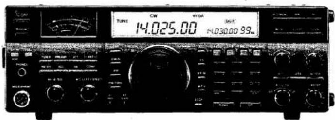
IMPORTANT
READ THIS INSTRUCTION MANUAL CAREFULLY before attempting to operate the transceiver.
SAVE THIS INSTRUCTION MANUAL—This instruction manual contains important safety and operating instructions for the IC-736 and IC-738.
PRECAUTIONS for the IC-736
⚠ DISCONNECT the AC power cable from the transceiver, and wait for a few minutes before performing AC fuse replacement or any internal work.
⚠ NEVER apply AC voltage that exceeds the suggested voltage for each version. The could cause a fire or ruin the transceiver.
⚠ NEVER use non-rated fuses. Non-rated fuses could cause a fire or ruin the transceiver.
⚠ NEVER let metal, wire or other objects touch any internal components.
⚠ NEVER expose the transceiver to rain, snow or any liquids.
NEVER allow children to touch the transceiver.
AVOID using or placing the transceiver in areas with temperatures below -10^ (+14°F) or above +60°C (+140°F).
AVOID placing the transceiver in excessively dusty environments or in direct sunlight.
AVOID placing the transceiver against walls or putting anything on top of the transceiver. This will obstruct heat dissipation.
In maritime mobile operation, keep the transceiver and microphone as far away as possible from the magnetic navigation compass to prevent erroneous indications.
BE CAREFUL! The heatsink will become hot when operating the transceiver continuously for long periods.
UNPACKING of the IC-736
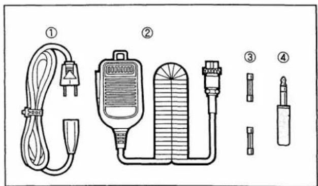
Accessories included with the IC-736: Qty.
① AC power cable 1
② Hand microphone (HM-36) 1
③ Spare fuses* 2
④ CW keyer plug 1
*10 A FGMB fuse for 100 - 120 V versions
5 A high breaking capacity fuse for 220 - 240 V versions
EXPLICIT DEFINITIONS
| WORD | DEFINITION |
| ⚠ WARNING | Personal injury, fire hazard or electric shock may occur. |
| CAUTION | Equipment damage may occur. |
| NOTE | If disregarded, inconvenience only. No risk of personal injury, fire or electric shock. |
The explicit definitions described at left apply to this instruction manual.
PRECAUTIONS for the IC-738
⚠ NEVER apply AC to the [DC 13.8V] socket on the transceiver rear panel. This could cause a fire or damage the transceiver.
NEVER apply more than 16 V DC to the [DC 13.8V] socket on the transceiver rear panel. This could cause a fire or damage the transceiver.
NEVER use non-rated fuses. Non-rated fuses could cause a fire or ruin the transceiver.
NEVER let metal, wire or other objects touch any internal components.
NEVER expose the transceiver to rain, snow or any liquids.
NEVER allow children to touch the transceiver.
AVOID using or placing the transceiver in areas with temperatures below -10^ (+14°F) or above +60°C (+140°F).
AVOID placing the transceiver in excessively dusty environments or in direct sunlight.
AVOID placing the transceiver against walls or putting anything on top of the transceiver. This will obstruct heat dissipation.
In any mobile operation, DO NOT operate the transceiver without running the vehicle's engine. The vehicle's battery will quickly run out if the transceiver power is ON while your vehicle's engine is OFF.
In maritime mobile operation, keep the transceiver and microphone as far away as possible from the magnetic navigation compass to prevent erroneous indications.
Make sure the transceiver power is OFF before starting the vehicle. This will avoid possible damage to the transceiver by ignition voltage spikes.
BE CAREFUL! The heatsink will become hot when operating the transceiver continuously for long periods.
UNPACKING of the IC-738
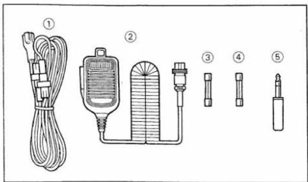
Accessories included with the IC-738: Qty.
① DC power cable (OPC-025A) 1
② Hand microphone (HM-36) 1
③ Spare fuse (FGB 20 A) 1
④ Spare fuse (FGB 4 A) .... 1
⑤ CW keyer plug 1
TABLE OF CONTENTS
IMPORTANT i
PRECAUTIONS for the IC-736 i
UNPACKING of the IC-736 i
EXPLICIT DEFINITIONS ...... ii
PRECAUTIONS for the IC-738 ii
UNPACKING of the IC-738 ii
TABLE OF CONTENTS iii
INDEX iv
FRONT PANEL INDEX iv
1 PANEL DESCRIPTION 1 - 10
■ Front panel 1
■ Rear panel 7
Function display 9
■ Microphone (HM-36) 10
2 INSTALLATION AND CONNECTIONS .... 11 - 16
■ Unpacking 11
■ Selecting a location 11
Grounding 11
Antenna 11
■ Connections diagram 12
■ DC power supply connections (IC-738) …… 13
Linear amplifier connections 14
External antenna selector or antenna tuner connections 15
■ AFSK terminal unit connections 16
3 BASIC OPERATION 17-26
When first applying power 17
■ Initial settings 17
Basic operation 18
■ VFO description 19
■ VFO mode and memory mode 19
Frequency setting with the main dial 21
■ Direct frequency entry with the keypad …… 21
■ Advanced tuning functions 22
■ Receiving 23
■ Transmitting 25
4 FUNCTION OPERATIONS 27-38
Memo pad operation 27
■ RIT and △TX 28
Split frequency operation 29
■ Quick split function 29
☐ VOX operation 30
Meter function 30
■ PBT operation 31
Notch operation 31
Set mode operation 32
■ Band memory (for automatic antenna selection) 36
■ Remote jack (CI-V) information 36
■ Antenna tuner operation 37
E Optional external tuner operation 38
5 MEMORY CHANNELS 39-44
■ Memory channels 39
■ Memory channel selection 39
Memory channel programming 40
Frequency transferring 41
■ Memory clearing 41
■ Scan edge memory channels 42
Split memory channels (for accessing a repeater) 43
6 SCANS 45-46
Scan types 45
■ Pre-operation 45
Programmed scan operation 46
■ Memory scan operation 46
■ Select memory scan operation 46
7 MAINTENANCE AND ADJUSTMENT .... 47 - 52
Frequency calibration (approximate) 47
■ Main dial brake adjustment 47
■ Fuse replacement (IC-736) 48
■ Fuse replacement (IC-738) 48
■ Opening the transceiver's case 49
LCD dimmer adjustment 49
AC power voltage selection (iC-736) 50
Tuner operating condition 50
PA idling current adjustment (IC-738) …… 51
Lithium backup battery 52
■ Cleaning 52
8 OPTIONS INSTALLATION 53-54
■ CW narrow filters 53
UT-30 PROGRAMMABLE TONE ENCODER UNIT · 53
CR-282 HIGH-STABILITY CRYSTAL UNIT 54
MB-49 MOBILE MOUNTING BRACKET 54
9 TROUBLESHOOTING 55-56
10 INTERNAL VIEWS 57-58
Main and PLL units 57
E Filter and Reg units (IC-736) 58
Filter unit (IC-738) 58
11 SPECIFICATIONS 59
12 OPTIONS 60-62
SCHEMATIC AND BLOCK DIAGRAMS ...... SEPARATE
Technical information
- ACC sockets 8
- Microphone connector and HM-36 schematic diagram 10
INDEX
A
AC power voltage selection 50
AF gain 2,23
AFSK 8,10,16,24,26
AGC (Automatic Gain Control) · 2, 23
ALC (Automatic Level
Control) 14,30
Accessory socket 7,8
Antenna connector 8,11
Antenna switch 2,34,36
Antenna tuner 1,37,38
Attenuator 2,23
B
Basic operation 18
Beep 32
Break-in 1,25
C
CI-V 7,35,36
CPU resetting 17
CW narrow filter 33,53
Compressor 2,7,25
D
DC power supply 8,13
TX 5,28
Dial lock 3,23,25,35
Display dimmer adjustment 49
E
Electronic CW keyer 2,7,25
External antenna selector 15
External antenna tuner 15,38
F
Frequency calibration 47
Full break-in 1,25
Fuse replacement 48
G
Grounding 8,11
H
High-stability crystal unit 54
K
Key speed 2,25
L
LCD dimmer adjustment 49
Linear amplifier 14
Lithium backup battery 52
Lock 3,23,25,35
M
Main dial brake 47
Memo pad 3,27,34
Memory channel 6,19,39
Memory scan 46
Meter 1,30
Microphone 1,10
Microphone gain 2,25
Mobile mounting bracket 54
N
Noise blanker 2,23
Notch filter 5,6,31
0
1 Hz tuning step 4,22
Option 60-62
P
PA idling current 51
PBT (PassBand Tuning) 6, 31
PTT (Push-To-Talk) 10, 18
Preamplifier 2,23
Programmed scan 46
Q
Quick split function 29
Quick tuning step 4,22
R
RF gain control 3,23
RF power control 3,25
RIT (Receive Incremental
Tuning) 5,28
Repeater 43
Resetting 17
S
S-meter 2
SWR (Standing Wave Ratio) · 11, 30
Scan 6,45
Scan edge 42,46
Select memory 6,46
Select memory scan 46
Semi break-in 1,25
Set mode 32-35
Specifications 59
Speech compressor 2,7,25
Split memory channel 43
Split operation 4,29
Squelch 2,23
T
Tone encoder 4, 43, 53
Transmit meter 1,30
Troubleshooting 55
U
Unpacking i, ii
V
VOX (Voice Operated
Relay) 1,7,25,30
Volume control 2,23
X
XFC (Transmit Frequency
Check) 4,29,30
FRONT PANEL INDEX
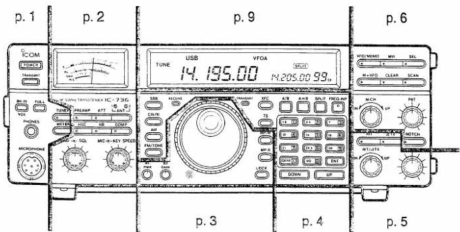
1 PANEL DESCRIPTION
Front panel

POWER SWITCH [POWER] (pgs. 23, 25) Turns power ON and OFF.

Power OFF

Power ON
② TRANSMIT SWITCH [TRANSMIT] (p. 25) Selects transmitting or receiving.

Receiving

Transmitting
③ BREAK-IN/VOX SWITCH [BK-IN/VOX] (pgs. 25, 30)
Turns the break-in operation for CW mode and VOX function for phone (SSB, AM and FM) operation ON and OFF.

OFF

FUNCTION
The VOX function (voice operated transmission) starts transmission without pushing the transmit switch or PTT switch when you speak into the microphone; then, automatically returns to receive when you stop speaking.
④ FULL BREAK-IN SWITCH [FULL] (p. 25)
Selects full break-in or semi break-in operation for CW operation when [BK-IN/VOX] is pushed IN.

Semi break-in

Full break-in
FUNCTION
Both semi and full break-in toggle transmit and receive with CW keying. Full break-in (QSK) can monitor the receive signal during keying.
⑤ HEADPHONE JACK [PHONES] (p. 23) Accepts headphones.
- Headphones with 4 – 16 Ω impedance can be used.
- When headphones are connected, the internal speaker or connected external speaker does not function.
⑥ MICROPHONE CONNECTOR [MICROPHONE] Accepts the supplied microphone.
- An optional Icom desktop microphone can be used.
• See p. 10 for microphone connector information.
⑦ ANTENNA TUNER SWITCH [TUNER] (pgs. 37, 38) -Turns the antenna tuner ON or OFF (bypass) when pushed momentarily.
-Starts to tune the antenna tuner manually when pushed and held.
- When the tuner cannot tune the antenna, the tuning circuit is bypassed automatically after 20 sec.

OFF (bypass)

ON
⑧ METER SWITCH [METER] (p. 30)
Selects the meter function as a power, SWR or ALC meter while transmitting.
- The meter activates only as an S-meter while receiving.
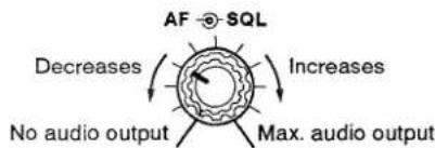
⑨ SQUELCH CONTROL [SQL] (outer control) (p. 23) Adjusts the squelch threshold level.

FUNCTION
The squelch removes noise output from the speaker (closed condition) when no signal is received. The squelch is particularly effective for FM. It is also available for other modes.
SETTING PROCEDURE
Squelch setting: When operating in FM, first rotate the control fully counterclockwise. Then, rotate the control clockwise to the point where the noise just disappears. This is the best position. The squelch does not open for weak signals when it is set too deep.
⑩ AF GAIN CONTROL [AF] (inner control) (p. 23) Varies the audio output level from the speaker.
① AGC SWITCH [AGC] (p. 23)
Changes the time constant of the AGC circuit.

AGC slow

AGC fast
FUNCTION
The AGC controls receiver gain to produce a constant audio output level even when the received signal strength is varied by fading, etc. Use AGC slow for normal operation and select AGC fast depending on the receiving condition. AGC does not function in FM mode.
⑫ NOISE BLANKER SWITCH [NB] (p. 23)
Turns the noise blanker ON and OFF.

OFF

ON
FUNCTION
The noise blanker reduces pulse-type noise such as that generated by automobile ignition systems. This function in not effective for AM and FM, or non-pulse-type noise.
ELECTRONIC CW KEYER SPEED CONTROL
[KEY SPEED] (outer control) (p. 25)
Adjusts the internal electronic CW keyer's speed.

⑭ MIC GAIN CONTROL [MIC] (inner control) (p. 25) Adjusts microphone input gain.

⑮ SPEECH COMPRESSOR SWITCH [COMP]
(p. 25)
Turns the speech compressor ON and OFF.
- The compression level must be adjusted properly. See 54 on the rear panel for details. (p. 7)

OFF

ON
FUNCTION
The speech compressor compresses the transmitter audio input to increase the average audio output level. Therefore, talk power is increased. This function is effective for long distance communication or when propagation conditions are poor.
⑯ ANTENNA SWITCH [ANT] (pgs. 34, 36)
Selects antenna 1 or 2.
- Antenna selection can be programmed depending on the band selection such as above 21 MHz band and below 18 MHz band, etc.

Antenna 1

Antenna 2
ATTENUATOR SWITCH [ATT] (p. 23)
Turns the 20 dB attenuator ON and OFF.

OFF

ON
FUNCTION
The attenuator prevents a desired signal from distorting when very strong signals are near the desired frequency or when very strong electric fields, such as from a broadcasting station are near your location.
18 PREAMP SWITCH [PREAMP] (p. 23)
Turns the preamp ON and OFF.

OFF

ON
FUNCTION
The preamp amplifies received singals in the front end circuit to improve the S/N ratio and sensitivity. Turn this function ON when receiving weak signals.
19 S/RF METER (p. 30)
Shows the signal strength while receiving. Shows the relative output power, SWR or ALC levels while transmitting.
1 PANEL DESCRIPTION

⑳ RF POWER CONTROL [RF PWR] (p. 25)
Continuously varies the RF output power from minimum (5 W for QRP operation) to maximum (100 W).

| MODE | Max. RF output | Min. RF output |
| SSB | 100 W | 5 W |
| CW | 100 W | 5 W |
| FM | 100 W | 5 W |
| AM | 40 W | 4 W |
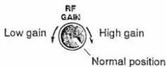
② RF GAIN CONTROL [RF GAIN] (p. 23)
Adjusts the receiver gain.
- This control should be set to the maximum clockwise position for normal use.
②2 BRAKE ADJUSTMENT SCREW (p. 47)
Adjusts the main dial tension.

②3 MAIN DIAL (p. 21)
Changes the displayed frequency.
24 MEMO PAD-WRITE SWITCH [MP-W] (p. 27)
Programs the displayed frequency and operating mode into a memo pad.
• The 5 most recent entries remain in memo pads.
- The memo pad capacity can be expanded from 5 to 10 in the set mode for your convenience. (p. 34)
② DIAL LOCK SWITCH [LOCK] (pgs. 23, 25)
Turns the dial lock function ON and OFF.
• The dial lock function electronically locks the main dial.
“LOCK” appears in the function display while the function is ON.
- The lock function can be deactivated only when changing the transmit frequency for split frequency operation using the set mode. (p. 35)
26 MEMO PAD-READ SWITCH [MP-R] (p. 27)
Each push calls up a frequency and operating mode in a memo pad. The 5 most recently programmed frequencies and operating modes can be recalled, starting from the most recent.
• The memo pad capacity can be expanded from 5 to 10 in the set mode for your convenience. (p. 34)
27 UP/DOWN TUNING SWITCHES [UP]/[DOWN] (p. 22)
Changes the displayed frequency up or down in programmed steps (1 kHz to 1 MHz).
28 KEYPAD (pgs. 21, 22)
- Pushing a key selects the operating band.
• [GENE] selects the general coverage band.
-Pushing the same key twice calls up another stacked frequency in the band.
- Icom's DBSR (Double Band Stacking Register) memorizes 2 frequencies in each band. (p. 21)
- After pushing [FREQ-INP], enters your desired frequency. Pushing [ENT] is necessary at the end.
(e.g. to enter 14.195 MHz, push [FREQ-INP][1][4][•][1][9][5][ENT].)
29 FREQUENCY-INPUT SWITCH [FREQ-INP] (p. 21)
Enables the keypad to input a frequency.
- The red indicator on the switch lights when pushed. While the red indicator lights, the keypad can be used to enter a frequency directly.
• To cancel the frequency input, push this switch again. The red indicator is turned OFF.
30 SPLIT SWITCH [SPLIT] (p. 29)
-Turns the split frequency function ON and OFF when pushed momentarily.
- Transmit frequency and "SPLIT" are indicated when the function is ON.
-Turns the split frequency function ON and equalizes the transmit frequency to the receive frequency when pushed for 1 sec.
- Split shift frequency can be pre-programmed to save time when DX'ing.
③ VFO EQUALIZATION SWITCH [A=B] (p. 29)
Equalizes the frequency and operating mode of the two VFOs when pushed for 1 sec.
- The rear (undisplayed) VFO frequency and operating mode are equalized to the front (displayed) VFO frequency and operating mode.
- This switch can be used even when the split frequency function is ON. In this case, the transmit frequency and operating mode are equalized to the receive frequency and operating mode.
③ VFO SWITCH [A/B] (p. 19)
- Toggles between VFO A and VFO B in the VFO mode.
- Toggles between transmit VFO and receive VFO when the split frequency function is ON.
- Toggles between the transmit frequency and operating mode and the receive frequency and operating mode in the split memory channels (memory channels 90 - 99).
③3 TRANSMIT FREQUENCY CHECK SWITCH [XFC] (pgs. 29, 30)
Monitors the transmit frequency when pushed and held when the split frequency function is ON.
- While pushing this switch, the transmit frequency can be changed with the dial, memo pad, or the [UP]/[DOWN] switches.
34 QUICK TUNING SWITCH [TS] (p. 22)
-Turns the quick tuning step ON and OFF.
- While this indicator is displayed, the frequency can be changed in programmed kHz steps.

-When pushed for 1 sec., turns the 1 Hz step ON and OFF.
- While this indicator is displayed, the frequency can be changed in 1 Hz steps.

③5 TRANSMIT INDICATOR [TRANSMIT] (p. 25)
Lights while transmitting.
③6 RECEIVE INDICATOR [RECEIVE] (p. 23)
Lights while receiving and when the squelch is open.
⑲ MODE SWITCHES (pgs. 23, 25)
Select the desired operating mode.

selects USB and LSB alternately.

selects "normal CW" and "CW-Narrow*" alternately.
*An optional CW filter is necessary.

selects AM.

selects FM and FM with a subaudible tone alternately.
To transmit a subaudible tone, an optional UT-30 PROGRAMMABLE TONE ENCODER UNIT is required.
“FM-T” indicates the subaudible tone encoder is ON.
1 PANEL DESCRIPTION

38 RIT SWITCH [RIT] (p. 28)
Turns the RIT function ON and OFF.
- “FIT\$” is indicated when the function is ON.
- Use the [RIT/ΔTX] control to vary the RIT frequency.
- The RIT function can be turned ON even when the TX function is ON.
• The RIT range is ±9.999 kHz. - Resets the RIT frequency to "0.000" when pushed and held.
FUNCTION
RIT (Receiver Incremental Tuning) shifts the receive frequency up to ±9.999 kHz in 1 Hz steps (or 10 Hz steps) without shifting the transmit frequency.
This is useful for fine tuning stations which call you on an off-frequency or when you prefer to listen to slightly different-sounding voice characteristics, etc.
39 RIT/ΔTX CONTROL [RIT/ΔTX] (p. 28)
Shifts the receive and/or transmit frequency while the RIT and/or TX functions are ON.
- Rotate the control clockwise to increase the receive/transmit frequency, or rotate the control counterclockwise to decrease the receive/transmit frequency.
![ICOM IC-736 - RIT/ΔTX CONTROL [RIT/ΔTX] (p. 28) - 1](/content/2026/05/862926/images/3c809bd58b01fb0e61d5be41beb3d86460f67bb8ff08966f9a574254edc63cf1.jpg)
40 TX SWITCH [ TX ] (p. 28)
Turns the TX function ON and OFF.
- “ TX ” is indicated when the function is ON.
- Use the [RIT/ΔTX] control to vary the ΔTX frequency.
- The TX function can be turned ON even when the RIT function is ON.
• The TX range is ±9.999 kHz. - Resets the TX frequency to "0.000" when pushed and held.
FUNCTION
TX shifts the transmit frequency up to ± 9.999 kHz in 1 Hz steps (or 10 Hz steps) without shifting the receive frequency. This is useful for simple split frequency operation in CW, etc.
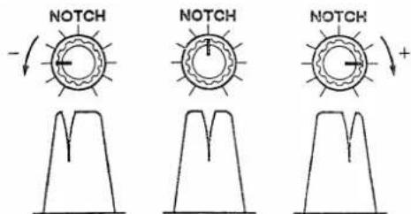
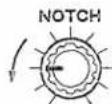
NOTCH CONTROL [NOTCH] (p. 31)
Adjusts the notch filtering frequency while the notch function is ON.
- Rotate the control clockwise or counterclockwise to shift the center of the notch filtering frequency.
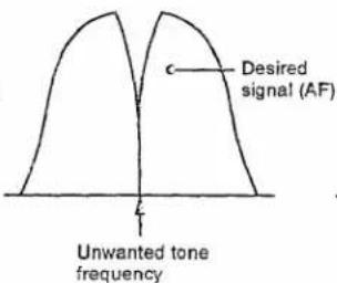
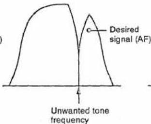
[Simplified example of the notch function]
42 NOTCH SWITCH [NOTCH] (p. 31)
Turns the notch function ON and OFF.
- The red indicator for the notch lights when the function is ON.
- Use the notch control to vary the filtering frequency.
![ICOM IC-736 - NOTCH SWITCH [NOTCH] (p. 31) - 1](/content/2026/05/862926/images/5ecf9ba436ebb692fd6323b031748a944ac76cc8e738177a611de7ef168b59c4.jpg)
OFF
![ICOM IC-736 - NOTCH SWITCH [NOTCH] (p. 31) - 2](/content/2026/05/862926/images/9da37795976fb05dd2f7f68e04a2570008b6caff90c1b91620a92c3d549ad885.jpg)
ON
FUNCTION
The notch function eliminates unwanted CW or AM carrier tones while preserving the desired signal's audio response. The filtering frequency must be adjusted to effectively eliminate an unwanted tone. An AF-type notch is adopted in the IC-736/738.
43 PASSBAND TUNING CONTROL [PBT] (p. 31)
Adjusts the receiver's "passband width" of the IF filter.
- Set to the center position when not in use.
FUNCTION
The PBT function electronically narrows the IF passband width to reject interference. The PBT is especially effective in SSB operation and not available in FM operation.
[Simplified example of the PBT function]


44 MEMORY CHANNEL SELECTOR [M-CH] (p. 39)
Selects a memory channel both in the VFO mode and the memory mode.
45 SCAN SWITCH [SCAN] (p. 46)
Starts and stops a scan.
- In the VFO mode, starts and stops programmed scan.
• In the memory mode, starts and stops memory scan.
46 CLEAR SWITCH [CLEAR] (p. 41)
Clears memory channel contents when pushed for 1 sec. in the memory mode.
- The channel becomes a blank channel and "BLANK" appears.
- This switch does not function in the VFO mode.
47 SELECT SWITCH [SEL] (p. 46)
- In the memory mode, designates or cancels the displayed memory channel as a select memory channel for select memory scan when pushed momentarily.
- "SELECT" appears when the displayed channel is a select memory channel.
-Cancels all select memory channels when pushed for 1 sec.
- "SELECT" disappears from all select memory channels.
48 MEMORY WRITE SWITCH [MW]
(pgs. 40, 42, 43)
Stores the displayed frequency and operating mode into the displayed memory channel when pushed for 1 sec.
- This switch functions both in the VFO mode and memory mode.
49 VFO/MEMORY SWITCH [VFO/MEMO] (p. 19)
Toggles between the VFO mode and memory mode.
⑤0 MEMORY TRANSFER SWITCH [M▶VFO]
(pgs. 41, 44)
Transfers the frequency and operating mode in a memory channel to a VFO when pushed for 1 sec.
- This switch functions both in the VFO mode and memory mode.
1 PANEL DESCRIPTION
■ Rear panel

⑤ VOX GAIN CONTROL [VOX GAIN] (p. 30)
Adjusts the transmit/receive switching threshold level for VOX operation.
⑤2 ANTI-VOX CONTROL [ANTI-VOX] (p. 30)
Adjusts the VOX deactivate level to prevent unwanted VOX control from the speaker audio.
⑤3 VOX/SEMI BREAK-IN DELAY CONTROL [DELAY] (pgs. 26, 30)
Adjusts the transmit-to-receive switching delay time for VOX and CW semi break-in operations.
Short delay for high speed keying

Long delay for low speed keying
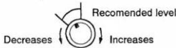
⑤4 SPEECH COMPRESSION LEVEL CONTROL [COMP LEVEL] (p. 25)
Adjusts the compression level.
⑤5 EXTERNAL SPEAKER JACK [EXT SP] (p. 12)
Accepts a 4 - 16 Ω speaker.
56 CI-V REMOTE CONTROL JACK [REMOTE] (p. 36)
Designed for use with a personal computer for remote operation of transceiver functions.
57 ELECTRONIC KEYER JACK [ELEC-KEY] (p. 12)
Accepts a paddle to activate the internal electronic keyer. (dot)

58 STRAIGHT KEY JACK [KEY] (p. 12)
Accepts a straight key or external electronic keyer with 1/4 inch standard plug.

If you use an external electronic keyer, make sure the voltage retained by the keyer is less than 0.4 V when the key is ON.
59 ACCESSORY SOCKETS [ACC (1) and (2)] (p. 8)
Enable connection to external equipment such as a linear amplifier, an automatic antenna selector/tuner, TNC for data communications, etc.
• See the page at right for socket information.
⑥0 ALC INPUT JACK [ALC] (p. 14)
Connects to the ALC output jack of a non-Icom linear amplifier.
• See p. 30 for the ALC function.
⑥ SEND CONTROL JACK [SEND] (p. 14)
Goes to ground while transmitting to control external equipment such as a linear amplifier.
• Max. control level: 16 V DC/2 A
62 AH-3 CONTROL SOCKET [TUNER] (p. 15)
Accepts the control cable from an optional AH-3 automatic antenna tuner.
⑥3 DC POWER SOCKET [DC 13.8V] (IC-738 only) Accepts 13.8 V DC through the supplied DC power cable. (p. 13)

natural_image
Pure electrical circuit lines without any symbolsRear panel view
64 GROUND TERMINAL (p. 11)
Connect this terminal to a ground to prevent electric shocks, TVI, BCI and other problems.
65 AC POWER SOCKET [AC] (IC-736 only) (p. 12)
Connects the supplied AC power cable to an AC outlet. 2 versions are available.
• 100 – 120 V AC (50/60 Hz) version
• 220 – 240 V AC (50/60 Hz) version
⚠ WARNING: NEVER apply AC voltage that exceeds the suggested voltage for each version. This could cause a fire or ruin the transceiver.
66 AC FUSE HOLDER [FUSE] (IC-736 only) (p. 48) Holds a fuse for the internal AC power supply. • 100 – 120 V versions: 10 A • 220 – 240 V versions: 5 A (High breaking) capability fuse
⚠ WARNING: NEVER use a non-rated fuse. This could cause a fire.
⑥7 ANTENNA CONNECTORS [ANT 1]/[ANT 2] (p. 12) Accept a 50 Ω antenna with a PL-259 plug.
NOTE: When using an optional AH-3 HF AUTOMATIC ANTENNA TUNER, connect it to the [ANT 1] connector. The internal antenna tuner activates for [ANT 2] and deactivates for [ANT 1] when connecting the AH-3.
TECHNICAL INFORMATION
- ACC SOCKETS
| ACC(1) | PIN NO. | PIN NAME | DESCRIPTION | SPECIFICATIONS |
 | 1 | NC | No connection. | — |
| 2 | GND | Connects to ground. | Connected in parallel with ACC(2) pin 2. | |
| 3 | SEND | Input/output pin.Goes to ground when transmitting.When grounded, transmits. | Ground level: -0.5 to 0.8 VInput current: Less than 20 mAConnected in parallel with ACC(2) pin 3. | |
| 4 | MOD | Modulator input.Connects to a modulator. | Input impedance: 10 kΩInput level: Approx. 100 mV rms. | |
| 5 | AF | AF detector output.Fixed, regardless of [AF] position. | Output impedance: 4.7 kΩOutput level: 100 – 350 mV rms | |
| Rear panel view | 6 | SQLS | Squelch output.Goes to ground when squelch opens. | SQL open: Less than 0.3 V/5 mASQL closed: More than 6.0 V/100 μA |
| 7 | 13.8 V | 13.8 V output when power is ON. | Output current: Max. 1 AConnected in parallel with ACC(2) pin 7. | |
| 8 | ALC | ALC voltage input. | Control voltage: -4 to 0 VInput impedance: More than 10 kΩConnected in parallel with ACC(2) pin 5. |
| ACC(2) | PIN NO. | PIN NAME | DESCRIPTION | SPECIFICATIONS |
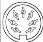 | 1 | 8 V | Regulated 8 V output. | Output voltage : 8 V ± 0.3 VOutput current : Less than 10 mA |
| 2 | GND | Same as ACC(1) pin 2. | ||
| 3 | SEND | Same as ACC(1) pin 3. | ||
| 4 | BAND | Band voltage output.(Varies with amateur band) | Output voltage : 0 - 8.0 V | |
| Rear panel view | 5 | ALC | Same as ACC(1) pin 8. | |
| 6 | TPS | Tuner selection voltage. | Output voltage : 4 - 5 V | |
| 7 | 13.8 V | Same as ACC(1) pin 7. | ||
1 PANEL DESCRIPTION
■ Function display

68 TUNING INDICATOR (pgs. 37, 38)
Appears when the antenna tuner is turned ON.
- Blinks when the antenna is being tuned.
69 THROUGH INDICATOR (pgs. 37, 38)
Appears when the antenna tuner is manually bypassed or when the tuner cannot match the connected antenna.
⑦ DIAL LOCK INDICATOR (p. 17)
Shows that the dial lock function is activated.
71 FREQUENCY READOUT (pgs. 21, 22)
Shows the operating frequency.
72 SUB VFO CONTROL INDICATOR (p. 29)
Shows that the main dial, mode switches, keypad, etc. control the sub VFO (for transmitting on the split frequency) setting.
- Appears when the split frequency function is ON and [XFC] is pushed or when transmitting.
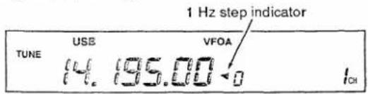
⑦ 1 Hz STEP INDICATOR (p. 22)
Shows that the 1 Hz step is selected.
- The left most digit of the RIT/ΔTX readout appears to show the 1 Hz digit.
74 RIT INDICATOR (p. 28)
Shows that the RIT function is ON.
75 RIT/△TX FREQUENCY READOUT (pgs. 28, 29)
- Show the RIT and/or TX variable frequency when operating in simplex.
- When the split function is ON, the sub VFO's frequency indication has priority.
- Shows the sub VFO's frequency for split frequency operation.
- Appears when the split frequency function is ON or a programmed split memory channel is selected.
76 MEMORY CHANNEL NUMBER READOUT
(p. 39)
Shows the selected memory channel number.
77 SELECT INDICATOR (p. 46)
Shows that the displayed memory channel is designated as a select memory channel.
⑦ BLANK INDICATOR (p. 41)
Shows that the displayed memory channel is a blank channel (and that it has not been programmed).
• This indicator appears even in the VFO mode.
79 SPLIT INDICATOR (p. 29)
Shows that the split frequency function is activated.
- Also appears when a programmed split memory channel is selected.
⑧0 MEMORY INDICATOR (pgs. 19, 39)
Shows that the memory mode is selected.
81 △TX INDICATOR (p. 28)
Shows that the TX function is ON.
⑧2 VFO INDICATORS (p. 19)
Show that the VFO mode is selected.
- Selected VFO (VFO A or VFO B) is indicated.
⑧3 QUICK TUNING INDICATOR (p. 22)
Shows that the quick tuning step is ON.
⑧4 MODE INDICATORS (pgs. 23, 25)
Show the operating mode.
85 EXT INDICATOR (p. 38)
Shows that an optional AH-3 is connected to the [ANT 1] connector and [ANT 1] is selected.
Microphone (HM-36)

86 UP/DOWN SWITCHES [UP]/[DN]
Change the operating frequency or memory channel.
- Continuous pushing changes the frequency or memory channel number continuously.
87 PTT SWITCH (p. 18)
Push and hold to transmit; release to receive.
TECHNICAL INFORMATION
• MICROPHONE CONNECTOR
[Front panel veiw]

| PIN NO. | FUNCTION | DESCRIPTION |
| 2 | +8 V DC output | Max. 10 mA |
| 3 | Frequency up | Ground |
| Frequency down | Ground through 470 Ω | |
| 4 | Squelch open | “LOW” level |
| Squelch closed | “HIGH” level |
CAUTION: DO NOT short pin 2 to ground as this can damage the internal 8 V regulator.
• HM-36 SCHEMATIC DIAGRAM

2 INSTALLATION AND CONNECTIONS
Unpacking
After unpacking, immediately report any damage or missing items to the delivering carrier or dealer. Keep the shipping cartons.
Selecting a location
Select a location for the transceiver that allows adequate air circulation, free from extreme heat, cold, or vibrations, and away from TV sets, radios and other electro-magnetic sources.
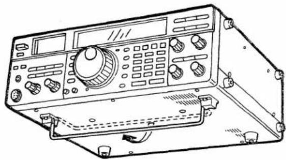
OPERATING ANGLE ADJUSTMENT
natural_image
Line drawing of a vintage oscilloscope with control panel and display (no text or symbols)The stand on the bottom of the transceiver provides two operating angles.
For a description and a diagram of accessory equipment included with the transceiver, see UNPACKING on the inside front page (p. i) of this manual.
Grounding
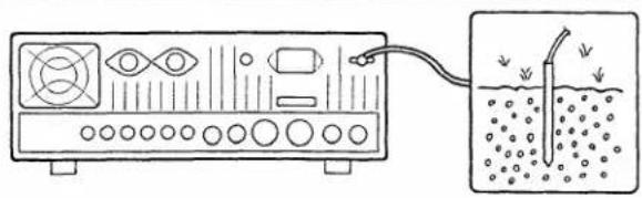
To prevent electrical shock, television interference (TVI), broadcast interference (BCI) and other problems, ground the transceiver through the GROUND terminal on the rear panel.
For best results, connect a heavy gauge wire or strap to a long earth-sunk copper rod. Make the distance between the GROUND terminal and ground as short as possible.
⚠ WARNING: NEVER connect the [GND] terminal to a gas or electric pipe, since the connection could cause an explosion or electric shock.
Antenna
Select antenna(s), such as well-matched 50 Ω antenna, and feedline. 1.5:1 or less of Voltage Standing Wave Ratio (VSWR) is recommended for your required band. Of course, the transmission line should be a coaxial cable.
When using 1 antenna, use the [ANT 1] connector.
CAUTION: Protect your transceiver from lightning by using a lightning arrestor.
PL-259 CONNECTOR INSTALLATION
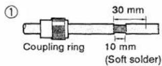
Slide the coupling ring down. Strip the cable jacket and soft solder.
③

Slide the connector body on and solder it.

Strip the cable as shown at left. Soft solder the center conductor.
④

Screw the coupling ring onto the connector body.
ANTENNA SWR
Each antenna is tuned for a specified frequency range and SWR may be increased out-of-range. When the SWR is higher than approx. 2.0 : 1, the transceiver's power drops to protect the final tran-
sistors. In this case, an antenna tuner is useful to match the transceiver and antenna. Low SWR allows full power for transmitting even when using the antenna tuner. The IC-736/738 has an SWR meter to monitor the antenna SWR continuously.
■ Connections diagram
![ANTENNA 1, 2 [Example] : ANT1 for 1.8–18 MHz bands ANT2 for 21–28(50) MHz bands AH-3 AUTOMATIC ANTENNA TUNER See pgs. 15, 38. AH-3 AH-2b ANTENNA ELEMENT (sold separately) When using the AH-3, it must be connected to the [ANT1] connector. IC-736 only AC OUTLET Use the specified AC voltage ONLY (indicated on the rear panel). GROUND The transceiver MUST be grounded through this terminal. When using 1 antenna, deactivate the [ANT] switch. See p. 34. Thick lines: Must be connected for operation. Thin lines: Recommended for convenient operation. EXTERNAL SPEAKER SP-21 CI-V REMOTE CONTROL See p. 36. Transceive function connection with another Icom HF transceiver or re- ceiver. Computer control connection through an optional CT-17 CI-V LEVEL CON- VERTER. CT-17 CW KEY A straight key or external electronic keyer to the [KEY] jack (A ⊕) (⊖) A paddle to the [ELEC-KEY] jack (dot) (com) (dash)](/content/2026/05/862926/images/9764933b2d060c3c51695dc03932626af791d9ac7a96078e8b78828bb4cb9b5f.jpg)
2 INSTALLATION AND CONNECTIONS
■ DC power supply connections (for the IC-738)
Use an optional PS-55, IC-PS15 or IC-PS30 DC POWER SUPPLY when operating the IC-738 with AC power. Refer to the diagram below.
NOTE: The PS-55 and IC-PS15 DC POWER SUPPLIES cannot be used with Europe versions. Use a non-Icom DC power supply as described in the diagram below.
CAUTION: Before connecting the DC power cable to the IC-738, check the following important items. Make sure:
• The [POWER] switch is OFF.
- Output voltage of the power source is 12 – 15 V when you use a non-Icom power supply.
- DC power cable polarity is correct.
Red : positive ⊕ terminal
Black : negative ⊖ terminal
CONNECTING AN ICOM DC POWER SUPPLY
![IC-738 DC power socket IC-PS15 When the IC-PS15 or PS-55 is connected to non-Europe versions, the power supply's power is synchronized with the [POWER] switch of the IC-738. DC power cable AC cable AC outlet](/content/2026/05/862926/images/29d281aff09ea6bf54b894b2ea13e58745734efc1f0ae79fc9b441b08948782d.jpg)
CONNECTING A NON-ICOM DC POWER SUPPLY

CONNECTING A VEHICLE BATTERY

NEVER connect to a 24 V battery.

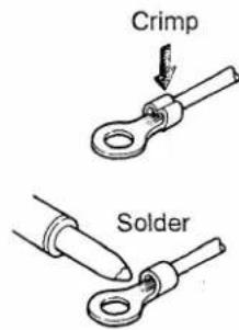
NOTE: Use terminals for the cable connections.
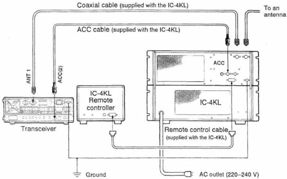
Linear amplifier connections
Use the [ANT 1] connector when connecting a linear amplifier.
CONNECTING THE IC-2KL

CONNECTING THE IC-4KL
CONNECTING A NON-ICOM LINEAR AMPLIFIER
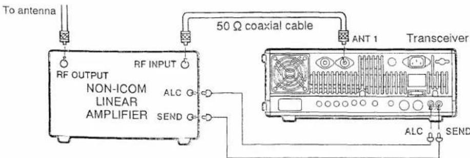
NOTE 1: The specifications for the SEND relay are 16 V DC 2 A. If this level is exceeded, a large external relay must be used.
NOTE 2: The ALC output level of the linear amplifier must be in the range 0 V to -4 V, and the transceiver does not accept positive voltage.
2 INSTALLATION AND CONNECTIONS
External antenna selector or antenna tuner connections
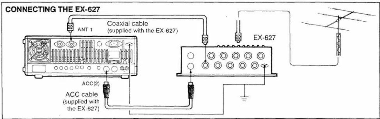
![CONNECTING THE AH-3 Coaxial cable (from the AH-3) ANT 1 Transceiver Use the [ANT 1] connector when connecting the AH-3. The internal tuner is deactivated on the [ANT 1] connector when a 4-pin plug is connected. AH-3 To the AH-2b or an antenna element](/content/2026/05/862926/images/354168078f7b9746b599a011cb326473e47f3bc8b1cfa84c9ce1b84a04c9ae1a.jpg)
![CONNECTING THE AT-150 A long wire antenna To a 50 Ω antenna AT-150 Coaxial cable (supplied with the AT-150) ANT 1 Transceiver ACC(2) ACC cable (supplied with the AT-150) Ground NOTE: When connecting the AT-150, turn the [TUNER] switch OFF to deactivate the internal antenna tuner.](/content/2026/05/862926/images/61e54f82292ca77c0408dda34cb29c35e04c1ccb8de5cbe1b881d37584c15813.jpg)

■ AFSK terminal unit connections
The transceiver does not have an FSK mode for RTTY, AMTOR, PACKET, etc., however, you can operate these using AFSK in SSB or FM mode.
When operating AFSK, connect external equipment to the ACC(1) socket on the rear panel or to the microphone connector on the front panel as in the diagram below.
Refer to pgs. 8 and 10 for ACC(1) socket information and microphone connector information.
When connected to the [MIC] connector, [MIC] control and [AF] control adjustment is required.
USING THE ACC(1) SOCKET
(Rear panel view)
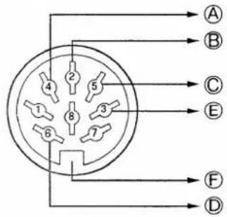
USING THE MICROPHONE CONNECTOR
(Front panel view)


flowchart
graph LR
    A["AFSK output"] --> B["AF input"]
    B --> C["SQUELCH input*"]
    C --> D["PTT"]
    D --> E["Ground (GND)"]
    E --> F["Computer"]
AFSK TERMINAL UNIT (TU) or TERMINAL NODE CONTROLLER (TNC)
*Connect the SQUELCH line (①) when required.
3
BASIC OPERATION
When first applying power
Before first applying power, make sure all connections required for your system are complete by referring to section 2. Then, reset the transceiver using the following procedure.
NOTE: Resetting CLEARS all programmed contents in memory channels and returns programmed values in the set mode to default values.
① Make sure the transceiver power is OFF.
② While pushing [CLEAR] and [ENT], push IN [POWER] to turn power ON.
• The internal CPU is reset.
- The display at right appears when resetting is complete.
[CPU RESETTING]
![[POWER] [CLEAR] [ENT]](/content/2026/05/862926/images/00ab9f8e5e89f3c806da9a8aaaa6b1879289eeb02f346c40df4ab76cc9c31c58.jpg)

Initial settings
After resetting the transceiver, set controls and switches as shown in the figure below.
: Set these switches and controls.
☐ : Make sure that these functions are not activated.
![[TUNER]: OFF [PREAMP]: OFF [AGC]: OFF (slow) [NB]: OFF [ATT]: OFF [ANT]: 1 [POWER]: IN [TRANSMIT]: OUT [BK-IN/VOX]: OUT [FULL]: OUT [AF]: CCW [SQL]: CCW [MIC]: CENTER [KEY SPEED]: CENTER [RF PWR]: CW [RF GAIN]: CW [COMP]: OFF [FREQ-INP]: OFF [PBT]: CENTER [NOTCH]: OFF [NOTCH]: CENTER CW : Max. clockwise CCW : Max. counterclockwise](/content/2026/05/862926/images/126c0872a9eec4492e38b5c309d0a4b75790a81c2596dd0b0bbfb12d19ae3f45.jpg)
Make sure the following indicators do NOT appear.
- RIT indicator, "RIT." - To turn the RIT indicator OFF, push [RIT].
- TX indicator, " TX ."
- To turn the TX indicator OFF, push [ TX ].
- Split indicator, "SPLIT." - To turn the split indicator OFF, push [SPLIT].
- Dial lock indicator, "LOCK." - To turn the dial lock indicator OFF, push [LOCK].
- Quick tuning step indicator, "√." - To turn the quick tuning step indicator OFF, push [TS].
Basic operation
- Phone (SSB, AM or FM) operation ① Make sure the initial settings are complete.

natural_image
Line drawing of a vintage electronic instrument with control panel and buttons (no text or symbols)② Rotate the main dial to set the desired frequency. • See pgs. 21 and 22 for frequency setting details.
③ Select the desired operating mode with [SSB], [AM] or [FM/TONE].

natural_image
Line drawing of a vintage electronic device with control panel and buttons (no text or symbols)④ Push and hold [TUNER] for 1 sec. to tune the antenna.
- "TUNE" appears when tuning is complete. - "THRU" appears after 20 sec. of attempted tuning, if the tuner cannot tune the connected antenna. In this case, check the antenna SWR (p. 30).

natural_image
Line drawing of a vintage electronic device control panel with buttons and dials (no text or symbols)⑤ Rotate [AF] clockwise to adjust the desired audio output level.

natural_image
Line drawing of a vintage electronic device with control panel and buttons (no text or symbols)⑥ Push the PTT switch on the microphone to transmit. Then, release the PTT switch to return to receive.
To eliminate noise, rotate [SQL] clockwise until the noise disappears.
- If [SQL] is rotated too deeply clockwise, the squelch will not open for weak signals.
- CW operation
① Make sure the initial settings are complete.
- A CW key or paddle must be connected to the appropriate jack on the rear panel.

natural_image
Front view of a vintage electronic device control panel with buttons and dials (no visible text or labels)② Rotate the main dial to set the desired frequency. • See pgs. 21 and 22 for frequency setting details.
③ Select the CW mode with [CW/N].
- If an optional CW narrow filter is installed, you can use the "CW-Narrow" mode.

natural_image
Front view of a vintage electronic instrument with control panel and buttons (no visible text or labels)④ Push and hold [TUNER] for 1 sec. to tune the antenna.
- "TUNE" appears when tuning is complete. - "THRU" appears after 20 sec. of attempted tuning, if the tuner cannot tune the connected antenna. In this case, check the antenna SWR (p. 30).
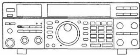
natural_image
Line drawing of a vintage electronic device front panel with control knobs and buttons (no text or symbols)⑤ Rotate [AF] clockwise to adjust the desired audio output level.
⑥ Push [BK-IN/VOX] IN to set the CW semi break-in operation.

natural_image
Line drawing of a vintage electronic device with control panel and buttons (no text or symbols)⑦ Push the key down and start transmitting.
- The transceiver returns to receive after your transmission ends.
3 BASIC OPERATION
VFO description
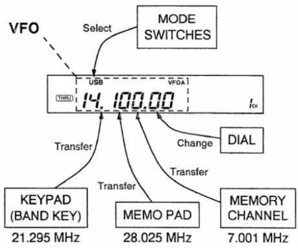
VFO is an abbreviation of Variable Frequency Oscillator, and traditionally refers to an oscillator.
The transceiver's VFO is somewhat different. The VFO of the IC-736/738 acts like a computer's window and can show one frequency and one operating mode.
You can call up a desired frequency to a VFO with the keypad, memo pad-read switch (see p. 27) or the memory transfer switch (see p. 41). You can also change the frequency with the main dial and select the operating mode with the mode switches.
The transceiver has two VFOs, specially suited for split frequency operation. The VFOs are called VFO A and VFO B. You can use the desired VFO to call up a frequency and operating mode for operation.
flowchart
graph TD
    A["VFO"] --> B["USB"]
    B --> C["THRU 14.100.00"]
    C --> D["DIAL"]
    C --> E["KEYPAD (BAND KEY) 21.295 MHz"]
    C --> F["MEMO PAD 28.025 MHz"]
    C --> G["MEMORY CHANNEL 7.001 MHz"]
    B --> H["Select MODE SWITCHES"]
    C --> I["Transfer"]
    C --> J["Transfer"]
    C --> K["Change"]
    C --> L["Transfer"]
VFO mode and memory mode
The IC-736/738 has 2 major modes, the VFO mode and the memory mode. You can set a frequency and operate the transceiver in either mode, however, use the VFO mode for most everyday operations. This is because temporarily set frequencies do not remain in the memory mode. See the next page for mode difference details.
The transceiver has 101 tunable memory channels in the memory mode for storing your often-used frequencies and operating modes. See pgs. 39–44 for memory mode operation.
The following diagram illustrates the mode construction.

flowchart
graph LR
    subgraph_VFO_mode["VFO mode"]
        A["USB THRU"] -->|USB 14.100.00 I_DH| B["VFOA VFOA"]
        C["Push"] -->|A/B| D["VFO B"]
        E["USB THRU"] --> F["VFOB 21.200.00 I_DH"]
    end

    subgraph_Memory_mode["Memory mode"]
        G["USB THRU"] --> H["MEMO"]
        I["USB THRU"] --> J["MEMO"]
        K["USB THRU"] --> L["MEMO"]
        M["USB THRU"] --> N["MEMO"]
        O["USB THRU"] --> P["MEMO"]
        Q["M-CH DN UP"] --> R["M-CH UP"]
    end

    style VFO_mode fill:#f9f,stroke:#333
    style Memory_mode fill:#bbf,stroke:#333
Frequency setting with the main dial
- For ham band use
① Push the desired band key on the keypad once or twice.
- 2 different frequencies can be selected on each band with the band key. (See DBSR in the box below.)

② Rotate the main dial to set the desired frequency.

③ Select the desired operating mode with the mode switches.
• For general coverage receiver use
① Push [GENE] on the keypad once or twice.
• The [GENE] key calls up a frequency for general coverage receiver use.

② Rotate the main dial to set the desired frequency.
- For quick tuning, use [UP]/[DOWN] switches or the quick tuning step function (p. 22).

③ Select the desired operating mode with the mode switches.
NOTE: If the dial lock function is activated, "LOCK" is indicated and the main dial does not function. In this case, push [LOCK] to deactivate the dial lock function.
FUNCTION
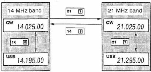
The DBSR (Double Band Stacking Register) provides 2 memories in one band. 2 sets of a frequency and mode on each band are automatically stored when used.
If a band key is pushed once, the last used frequency and mode are called up. When the key is pushed again, another stored frequency and mode are called up.
This function is convenient when you operate 2 modes on one band. For example, one register is used for a CW frequency and another register for an SSB frequency.
[DBSR EXAMPLE]
flowchart
graph TD
    A["14 MHz band"] -->|CW 14.025.00| B["21 MHz band"]
    A -->|USB 14.195.00| B
    B -->|CW 21.025.00| C["21 MHz band"]
    B -->|USB 21.295.00| C
    A -->|CW 14.025.00| D["21 MHz band"]
    A -->|USB 14.195.00| D
    D -->|CW 21.025.00| E["21 MHz band"]
    D -->|USB 21.295.00| E
    style A fill:#f9f,stroke:#333
    style B fill:#ccf,stroke:#333
    style C fill:#cfc,stroke:#333
Direct frequency entry with the keypad
The transceiver has a keypad for direct frequency entry as described below.
① Push [FREQ-INP].
• The red indicator on the switch lights.
② Input the desired frequency.
- Input "-" (decimal point) between the MHz units and kHz units.
③ Push [ENT] to enter the input frequency.
- When input is complete, the red indicator on [FREQ-INP] is turned OFF.
To cancel input, push [FREQ-INP] instead of [ENT].
[EXAMPLE]
14.025 MHz
FREQ-INP
18.0725 MHz
![ICOM IC-736 - [EXAMPLE] - 1](/content/2026/05/862926/images/1615c3f03a8f06261b7f7c355b8e00961012f8ebdb662ec2dbdad48f20ccbc70.jpg)
![ICOM IC-736 - [EXAMPLE] - 2](/content/2026/05/862926/images/bf4a290895442d3b2c272cdc04dc6ddddbb4b42a425037d433aaf4aefa1c054e.jpg)
![ICOM IC-736 - [EXAMPLE] - 3](/content/2026/05/862926/images/5c293267a1e15480e130301701e6e785b410ffe0119907e9e87970609aca7229.jpg)
![ICOM IC-736 - [EXAMPLE] - 4](/content/2026/05/862926/images/cb158bd185076e953a569a7b1fc20940dfb4ce6098c2792802edaf7a5edf0b65.jpg)
729 kHz
FREQ-INP
![ICOM IC-736 - [EXAMPLE] - 5](/content/2026/05/862926/images/faacef09dd7f042d97003bb4d89a18c91521e378548f9eac40441ce2a4936609.jpg)
![ICOM IC-736 - [EXAMPLE] - 6](/content/2026/05/862926/images/5c66606591a4e2a631e4e5fc8c894f0446bf979ade5e3ad8f3522574fd3b74b2.jpg)
![ICOM IC-736 - [EXAMPLE] - 7](/content/2026/05/862926/images/0bd7d4c50e39323448dfa053419dbac64abb9967dcf4565e258b83579c540fff.jpg)
![ICOM IC-736 - [EXAMPLE] - 8](/content/2026/05/862926/images/e0a35d44f27a2a7e4a074c046d867ca8b0de1ad2514d5e32f970d41b776c3eb5.jpg)
FREQ-INP
![ICOM IC-736 - [EXAMPLE] - 9](/content/2026/05/862926/images/69a45b59e90a9af569043208377302091ac4c1018629b5b551c6559c83dc5e56.jpg)
![ICOM IC-736 - [EXAMPLE] - 10](/content/2026/05/862926/images/bc7498517738f53eb20b442653c5149574325ceded6b07f66e6e95edf6eed195.jpg)
![ICOM IC-736 - [EXAMPLE] - 11](/content/2026/05/862926/images/2a9e4aafeee2d81ef12bddedfd7f296ea8357c068cc7b5ec82d2204dea9aec89.jpg)
![ICOM IC-736 - [EXAMPLE] - 12](/content/2026/05/862926/images/6563addbc7251e32aa0b9aeafc49cd161e11e6efe83ad03aff3084b8c7c2dd5f.jpg)
5.100 MHz
7.000 MHz
21.280→21.245
FREQ-INP
![ICOM IC-736 - [EXAMPLE] - 13](/content/2026/05/862926/images/17977d57fd16a57304ebf7a7403b2b633e935bbbfa731e2567b51bae71aba4c6.jpg)
![ICOM IC-736 - [EXAMPLE] - 14](/content/2026/05/862926/images/6ac44a395b41f2be7419ff9762b4be27d506c9bc6b498a5cfaff1dc2a35014f8.jpg)
![ICOM IC-736 - [EXAMPLE] - 15](/content/2026/05/862926/images/01fe4f1204f0c11c742097b6325937a2de36b9aa7b01f3760dfcb3bd2124cacf.jpg)
FREQ-INP
![ICOM IC-736 - [EXAMPLE] - 16](/content/2026/05/862926/images/b905a7f28960addfba9d38f1293cae03de0aa0159ca70c719b4184e9ccbc611d.jpg)
![ICOM IC-736 - [EXAMPLE] - 17](/content/2026/05/862926/images/4fd6b6f99dd66b3ad6e6d554369b0f1a4bfae132f34068c072e2125d61ddcc76.jpg)
FREQ-INP
![ICOM IC-736 - [EXAMPLE] - 18](/content/2026/05/862926/images/c857f931de6e182c90705abc16aef6d522f1338fb87361eb8c3ab3ff0dd4fbfb.jpg)
![ICOM IC-736 - [EXAMPLE] - 19](/content/2026/05/862926/images/6970db1513496bce4c5c0a9eeb3145b8c5d61352c6300ba8ae90ec786025e988.jpg)
![ICOM IC-736 - [EXAMPLE] - 20](/content/2026/05/862926/images/46aa8404b60c895d30141301fdded662a48f7f8141b82032175bc6e8c554c518.jpg)
Advanced tuning functions
QUICK TUNING STEP
The operating frequency can be changed in kHz steps (1 - 10 kHz programmable) for quick tuning.
① Push [TS] to display the quick tuning indicator.

② Rotate the main dial to change the frequency in programmed kHz steps.
③ Push [TS] again to turn OFF the indicator.
④ Rotate the main dial for normal tuning if required.

natural_image
Front view of a standard analog oscilloscope with control panel and display (no visible text or labels)Programming the kHz step
① Push [FREQ-INP].
② Enter the desired kHz step with the digit key(s), [1] - [1][0].
③ Push [TS] to set the entered kHz step.
(e.g. For a 9 kHz step, push [FREQ-INP][9][TS].)
SELECTING THE 1 Hz STEP
The minimum tuning step of 1 Hz can be used for fine tuning.
Push and hold [TS] for 1 sec. to activate the 1 Hz tuning step; push again to deactivate it.

natural_image
Line drawing of a vintage electronic device with control panel and buttons (no text or symbols)NOTE: When RIT/ΔTX or the split frequency function is selected, the 1 Hz readout disappears. However, the 1 Hz step indicator remains to show that the 1 Hz step is still active.
[UP]/[DOWN] SWITCH TUNING
The [UP]/[DOWN] switches change the frequency in programmed steps for large frequency changes. You can set this tuning step from 1 kHz – 1 MHz (in 1 kHz intervals).
![ICOM IC-736 - [UP]/[DOWN] SWITCH TUNING - 1](/content/2026/05/862926/images/ab417b2d0802b64214f49b299400052c1ca2f88b4fbaba6d8d411c70a7346a42.jpg)
Programming the [UP]/[DOWN] switch tuning steps
① Push [FREQ-INP].
② Enter the desired step with the digit key(s), [1] - [1][0][0][0].
③ Push [UP] or [DOWN].
(e.g. For a 5 kHz step, push [FREQ-INP][5][UP]. For a 1 MHz step, push [FREQ-INP][1][0][0][0][UP].)
CHANGING THE NORMAL TUNING STEP
The transceiver's normal tuning step default setting is 10 Hz. However, this can be changed to 20 Hz or 50 Hz as follows.
- For a 10 Hz step, push [FREQ-INP][0][.][1][TS].
- For a 20 Hz step, push [FREQ-INP][0][.][2][TS].
- For a 50 Hz step, push [FREQ-INP][0][.][5][TS].

natural_image
Front view line drawing of a vintage electronic device control panel (no text or symbols visible)AUTO TUNING STEP FUNCTION
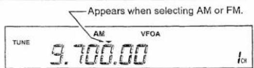
When selecting AM or FM, the quick tuning step indicator is automatically selected by the auto tuning step function. This function can be turned ON and OFF as desired in the set mode. (p. 32)

Receiving
![ATT (17 on p. 2) Push this switch to use the attenuator for reduc- ing distortion from strong signals. S/RF METER Shows the receive signal strength. PREAMP (18 on p. 2) Push to use the preamp for receiving weak sig- nals. POWER Push IN to turn power ON. PHONES Insert head- phones when required. SQL (9 on p. 2) Rotate to close the squelch when you want to eliminate the floor noise. AF Rotate to adjust the au- dio output level. AGC (11 on p. 2) Push when AGC fast is necessary. ANT (pgs. 2, 34) Push this switch to select an antenna when 2 an- tennas are connected. RECEIVE Lights UP in green when receiving with the squelch open. FUNCTION DISPLAY Shows the receive fre- quency, operating mode, etc. USB 14.195.00 VFOA 14.205.00 99.00 NOTCH (pgs. 5, 31) Push the [NOTCH] switch; then, ro- tate the [NOTCH] control to adjust the notch filtering frequency to cut beat signals. REF GAIN (21 on p. 3) Adjust the re- ceiver gain when an undesired sig- nal is received. SBB, CW/N, AM, FM/TONE Select the desired operating mode with these switches. NB (12 on p. 2) Push to use the noise blanker function for re- ducing pulse-type noise. RIT (pgs. 5, 28) Push [RIT] to indicate " RIT," then rotate [RIT/ΔTX] to shift your receive frequency. • Transmit frequency is not shifted regardless of the RIT function. PBT (pgs. 6, 31) Rotate the PBT control to reduce interference. • PBT does not function in FM. MAIN DIAL (p. 21) Set the desired fre- quency with this dial.](/content/2026/05/862926/images/38c30990ee3a54f86ad6d1ca8984f0268fc451ddf04f2a85c1bb4426b15fe7f6.jpg)
☐ : Required operations
□ : Convenient functions
SSB RECEIVING
① Turn power ON with [POWER].
② Set the desired frequency.
③ Select USB or LSB with [SSB].
• The [SSB] switch selects USB and LSB alternately.
- USB is normally used in ham bands above 10 MHz, and LSB is normally used in ham bands below 10 MHz.
④ Adjust the audio output level with [AF].
Convenient functions for SSB receiving
- NB (Noise Blanker)
- ATT (Attenuator)
- PREAMP (Pre-amplifier)
• AGC (Auto Gain Control)
• PBT (Passband Tuning)
• RIT (Receiver Incremental Tuning) - NOTCH
- LOCK (Dial lock)
• SQUELCH
• RF GAIN
CW RECEIVING
① Turn power ON with [POWER].
② Set the desired frequency.
③ Select CW with [CW/N].
- The [CW/N] switch selects normal CW or CW-Narrow (CW-N) alternately.
④ Adjust the audio output level with [AF].
Convenient functions for CW receiving
- NB (Noise Blanker)
- ATT (Attenuator)
• PREAMP (Pre-amplifier)
• AGC (Auto Gain Control)
• PBT (Passband Tuning)
• RIT (Receiver Incremental Tuning) - NOTCH
- LOCK (Dial lock)
• SQUELCH - CW-Narrow mode (An optional CW filter is necessary.)
- RF GAIN
AM RECEIVING
① Turn power ON with [POWER].
② Set the desired frequency.
③ Select AM with [AM].
④ Adjust the audio output level with [AF].
Convenient functions for AM receiving
- ATT (Attenuator)
• PREAMP (Pre-amplifier)
• AGC (Auto Gain Control)
• RIT (Receiver Incremental Tuning)
• NOTCH - LOCK (Dial lock)
• SQUELCH
• NB (Noise Blanker)
• AUTO TUNING STEP (pgs. 22, 32) - RF GAIN
FM RECEIVING
① Turn power ON with [POWER].
② Set the desired frequency.
③ Select FM with [FM/TONE].
④ Adjust the audio output level with [AF].
⑤ Rotate [SQL] clockwise until noise disappears.
Convenient functions for FM receiving
- ATT (Attenuator)
• PREAMP (Pre-amplifier)
• RIT (Receiver Incremental Tuning)
• NOTCH - LOCK (Dial lock)
• AUTO TUNING STEP (pgs. 22, 32)
AFSK (RTTY, AMTOR, PACKET, etc.) RECEIVING
(External equipment is necessary.)
① Turn power ON with [POWER].
② Set the desired frequency.
③ Select LSB, USB or FM.
- LSB is normally used.
• FM is used for PACKET on 29 MHz.
④ Adjust the audio output level with [AF].
- Use [SQL] when required.
Operating notes for RTTY and AMTOR receiving
- RTTY or AMTOR operating frequency in LSB mode differs from the displayed frequency.
[Your operating freq.] = [Displayed freq.] - 2125 Hz (when the frequencies of the RTTY demodulator in your TU or TNC are mark = 2125 Hz and space = 2295 Hz).
Operating notes for PACKET receiving
- PACKET operating frequency in LSB mode differs from the displayed frequency.
[Your operating freq.] = [Displayed freq.] - 2215 Hz (when the frequencies of the PACKET demodulator in your TNC are 2115 Hz / 2315 Hz).
3 BASIC OPERATION
Transmitting
NOTE: Transmission is possible only within the ranges listed in the specifications on p. 59.
![ANT (pgs. 2, 34) Push to select the antenna when 2 antennas are connected. COMP (15, 54 on pgs. 2, 7) Push [COMP] then, adjust the compression level with [COMP LEVEL] on the rear panel to use the speech compressor for increasing the level of average talk power. COMP Level setting: Rotate [COMP LEVEL] on the rear panel to get adequate compression but no distortion while monitoring your transmitted voice signal with another HF receiver. METER/METER SWITCH (p. 30) The meter has 3 functions while transmitting: ① RF meter ② ALC meter ③ SWR meter SSB, CW/N, AM, FM/TONE Select the desired operating mode. TUNER (pgs. 1, 37) -Push to activate the tuner. -Push and hold to tune the antenna manually. MAIN DIAL (p. 21) Set the desired frequency with this dial. TRANSMIT Lights UP in red when transmitting. POWER Push IN to turn power ON. KEYPAD (p. 21) Select the desired band or enter the desired frequency directly with the keypad. TRANSMIT Push IN to transmit and push OUT to receive. Same function as the PTT on the microphone. LOCK Push to activate the dial lock function. RF PWR (p. 3) Rotate to set the desired RF output power. ΔTX (pgs. 5, 28) Push [ΔTX] to indicate "ΔTX," then rotate [RIT/ΔTX] to shift your transmit frequency. ● Receive frequency is not shifted regardless of the ΔTX function. VOX FUNCTION (pgs. 1, 30) Push [BK-IN/VOX] IN to use the VOX function for hands-free operation. The [VOX GAIN], [ANTI-VOX] and [DELAY] controls are located on the rear panel. KEY SPEED (p. 2) Rotate to adjust the internal electronic keyer when used. MIC GAIN (p. 2) Set to the 10 – 12 o'clock position when using the supplied microphone. BK-IN/FULL (p. 1) Push [BK-IN/VOX] IN to use the break-in function for auto T/R switching in CW operation. Push [FULL] IN to activate the full break-in (QSK) function. Push [FULL] OUT to use the semi break-in function. SETTING PROCEDURE Mic gain setting: While transmitting in SSB mode, rotate [MiC] to adjust the mic gain so that the ALC meter sometimes swings at your normal voice level. SETTING PROCEDURE Mic gain setting: While transmitting in SSB mode, rotate [MiC] to adjust the mic gain so that the ALC meter sometimes swings at your normal voice level.](/content/2026/05/862926/images/3a575d9fb8640cbc23cd08acff2b276308b02e59a5b623c343e98b17096de766.jpg)
SSB TRANSMITTING
① Set for SSB (USB or LSB) receiving.
② Set the frequency within your allowed frequency range for SSB transmitting.
③ Set the desired RF output power with [RF PWR].
④ Push and hold the PTT switch on the microphone and speak into the microphone.
Operating notes for SSB transmitting
- [MIC] should be set correctly. When using a non-Icom microphone, set [MIC] referring to "SETTING PROCEDURE" described on the page at left.
Convenient functions for SSB transmitting
• COMP (Speech compressor)
• VOX
• ΔTX
• ALC/SWR METER
CW TRANSMITTING
(An external CW keyer or a paddle is necessary.)
① Set for CW receiving.
② Set the frequency within your allowed frequency range for CW transmitting.
③ Set the desired RF output power with [RF PWR].
④ Push [BK-IN] IN (and [FULL] IN when desired).
⑤ Push the key down and start CW transmitting.
⑥ Adjust [DELAY] to a suitable speed for returning from transmit to receive when selecting semi break-in operation.
Operating notes for CW transmitting
- The break-in function automatically starts transmitting when the key is down, and then returns to receive. If you want to switch transmitting/receiving manually, turn the break-in function OFF. You can use the [TRANSMIT] switch to change between transmitting and receiving.
Convenient functions for CW transmitting
• Full or semi break-in
• Semi break-in delay control
- Internal electronic keyer with keying speed control
- Independent jack for paddle and straight key.
- Side tone level preset (Internal setting; p. 57)
• ΔTX
AM TRANSMITTING
① Set for AM receiving.
② Set the frequency within your allowed frequency range for AM transmitting.
③ Set the desired RF output power with [RF PWR].
④ Push and hold the PTT switch on the microphone and speak into the microphone.
Operating notes for AM transmitting
- [MIC] should be set correctly. When using a non-Icom microphone, set [MIC] by monitoring another HF receiver.
Convenient functions for AM transmitting
• COMP (Speech compressor)
• VOX
• ΔTX
FM TRANSMITTING
① Set for FM receiving.
② Set the frequency within your allowed frequency range for FM transmitting.
③ Set the desired RF output power with [RF PWR].
④ Push and hold the PTT switch on the microphone and speak into the microphone.
Operating notes for FM transmitting
- [MIC] should be set correctly. When using a non-Icom microphone, set [MIC] by monitoring another HF receiver.
Convenient functions for FM transmitting
• COMP (Speech compressor)
- FM TONE (Subaudible tone; an optional UT-30 is necessary.)
• VOX
AFSK TRANSMITTING
(External equipment is necessary.)
① Set for AFSK receiving. (LSB is normally used.)
② Set the frequency within your allowed frequency range for AFSK transmitting.
③ Set the desired RF output power with [RF PWR].
- When using the [MICROPHONE] connector for external equipment connection, [MIC] should be adjusted.
④ Push [TRANSMiT] IN or send a TX control signal from the external TU or TNC; then, start transmitting your AFSK signal.
Operating notes for AFSK transmitting
- AFSK operating frequency differs from the displayed frequency. Refer to the formula described on p. 24.
Frequency setting example for AFSK transmitting
- When operating RTTY at 14.090 MHz: Set "LSB 14.092125 MHz" (if you use mark=2125 Hz / space=2295 Hz).
- When operating PACKET at 14.110 MHz: Set "LSB 14.112215 MHz" (if you use 2115 Hz / 2315 Hz).
4 FUNCTION OPERATIONS
■ Memo pad operation
The IC-736/738 has a memo pad function to store frequency and operating mode for easy write and recall. The memo pads are separate from memory channels.
The default number of memo pads is 5, however this can be increased to 10 in the set mode if needed. (p. 34).
The memo pad function is convenient when you want to memorize a frequency and operating mode temporarily, such as when you find a DX station in a pile-up or when a desired station is busy for a long time and you want to search for other stations.
Use these memo pads instead of inconvenient paper memo pads for writing frequencies.
- Writing frequencies and operating modes into memo pads
You can simply write the displayed frequency and operating mode by pushing the [MP-W] switch.
When you write a 6th frequency and operating mode, the oldest written frequency and operating mode are automatically erased to make room for the new settings.
NOTE: Each memo pad must have its own unique combination of frequency and operating mode, memo pads containing identical settings cannot be written.

other
| Position | Value | | -------- | --------- | | Newest | 14.195.00 | | Oldest | 21.276.00 | | Push | MP-W | | Displayed freq. and mode | USB 21.288.22 |- Calling up a frequency from a memo pad
You can simply call up the desired frequency and operating mode of a memo pad by pushing the [MP-R] switch one or more times.
- Both VFO and memory modes can be used.
- The frequency and operating mode are called up, starting from the most recently written.
When you call up a frequency and an operating mode from memo pads with [MP-R], the previously displayed frequency and operating mode are automatically stored in a temporary pad. The frequency and operating mode in the temporary pad can be recalled by pushing [MP-R] one or more times.
- You may think there are 6 memo pads because 6 different frequencies (5 are in memo pads and 1 is in the temporary pad) are called up by [MP-R].
NOTE: If you change the frequency or operating mode called up from a memo pad with the main dial, etc., the frequency and operating mode in the temporary pad are erased.

other
| Category | Value | | ------------------ | --------- | | USB | 14.195.00 | | USB | 14.182.40 | | USB | 21.018.06 | | USB | 21.024.52 | | USB | 21.276.00 | | TEMPORARY PAD | 28.485.00 |RIT and △TX
- RIT function
The RIT function shifts the receive frequency up to ±9.999 kHz in 1 Hz steps (10 Hz steps when clearing the 1 Hz step indicator) without moving the transmit frequency.
• See 38 on p. 5 for function description.
① Push the [RIT] switch.

② Rotate the [RIT/ TX] control.

③ To reset the RIT frequency, push and hold [RIT] for 1 sec.
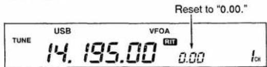
④ To cancel the RIT function, push [RIT] again.
- "RIT" disappears.
PRACTICAL EXAMPLE
When you find a DX station on 21.025 MHz/CW and the station is picking up stations transmitting slightly up from 21.025 MHz.
① Push [RIT] and [ TX] to turn both the RIT and TX functions ON.
② Rotate [RIT/ΔTX] to find the DX station's receive frequency.
③ When you find the DX station's receive frequency, push [RIT] to turn the RIT function OFF.
- Now you can transmit the DX station's receive frequency and receive the DX station's transmit frequency (21.025 MHz).
④ Start transmitting while the station is standing by.
PRACTICAL EXAMPLE
You find a DX station operating in simplex, however, you have not yet tuned your antenna (or your linear amplifier), and you do not want to transmit your tuning tone on the DX station's frequency.
① Push [ TX ] to turn the TX function ON.
② Rotate [RIT/ΔTX] to more than ±2 kHz.
③ Push and hold [TUNER] to tune your antenna.
- Or, tune your linear amplifier with key ON in the CW mode.
④ Push [ TX ] to turn the TX function OFF.
⑤ Start transmitting while the station is standing by.
- TX function
The TX function shifts the transmit frequency up to ±9.999 kHz in 1 Hz steps (10 Hz steps when clearing the 1 Hz step indicator) without moving the receive frequency.
• See 40 on p. 5 for function description.
① Push the [ TX] switch.

② Rotate the [RIT/ TX] control.

③ To reset the TX frequency, push and hold [ TX ] for 1 sec.
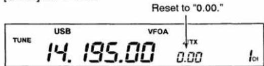
④ To cancel the TX function, push [ TX] again.
- "ΔTX" disappears.
When RIT and TX are ON at the same time, the [RIT/ TX ] control shifts both the transmit and receive frequencies from the displayed frequency at the same time.
• Calculate function
The shift frequency of the RIT or TX function can be added/subtracted to the displayed frequency.
While displaying the RIT and/or TX shift frequency, push [FREQ-INP], then push and hold [RIT] or [ TX ].

4 FUNCTION OPERATIONS
Split frequency operation
Split frequency operation allows you to transmit and receive on two different frequencies.
The split frequency operation is basically performed using 2 frequencies on 2 VFOs.
Following is an example of setting 21.290 MHz for receiving and 21.310 MHz for transmitting.
① Set 21.290 MHz (USB) in the VFO mode.
- Both VFO A and VFO B can be used.

② Push [SPLIT], then push and hold [A=B].
- The quick split function is much more convenient for selecting the transmit frequency.
- Equalized transmit frequency and "SPLIT" appear.

③ While pushing [XFC], rotate the main dial to set the transmit frequency to 21.310 MHz.

Now you can receive on 21.290 MHz and transmit on 21.310 MHz.
- “▶” appears while transmitting. It indicates the sub VFO frequency (21.310 MHz) is being used for transmitting.
To change the transmit and receive frequencies, push [A/B] to exchange VFOs.
NOTE: The transceiver has 10 split memory channels (memory channels 90 - 99) which each store 2 frequencies for split frequency operation. See pgs. 43, 44 for details.
CONVENIENT
DIAL LOCK FUNCTION
The dial lock function is convenient for changing only the transmit frequency. Otherwise, accidentally releasing the [XFC] switch while rotating the main dial changes the receive frequency. The dial lock's effectiveness can be selected in the set mode for both receive and transmit frequencies; or only the receive frequency.
Quick split function
When you find a DX station, an important consideration is how to set the split frequency. If you can anticipate the necessary shift frequency, it can be pre-programmed into the quick split function.
When you push and hold the [SPLIT] switch, split frequency operation is turned ON and the sub VFO appears with the same operating mode and the plus/minus pre-programmed shift frequency from the main VFO (or equalized when not programmed).

This shortens the time needed to start split frequency operation.
The quick split function is ON by default. For your convenience, it can be turned OFF in the set mode. In this case, the [SPLIT] switch does not equalize the VFO frequencies.
PROGRAMMING SPLIT SHIFT FREQUENCY
① Push [FREQ-INP].
② Enter the desired shift frequency with the digit key(s).
- 1 kHz to 1 MHz can be programmed.
- When you require a minus shift direction, push [•] in advance.
③ Push [SPLIT].
[EXAMPLE]
To program 1 kHz shift frequency:
To program -3 kHz shift frequency:
To clear the shift frequency:
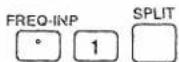
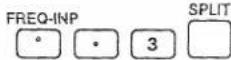

NOTE: The added or subtracted sub VFO frequency will be equalized to the main VFO when the [VFO/MEMO] switch is pushed.
PRACTICAL EXAMPLE
When you are searching for DX stations and you suspect that a DX station may say "up 'X' kHz" for their receive frequency:
PRE-OPERATION
① Program 10 kHz for the shift frequency.
- Push [FREQ-INP], [1], [0], [SPLIT].
② Program 5 kHz for the [UP]/[DOWN] switches.
- Push [FREQ-INP], [5], [UP].
OPERATION
① When the DX station says "up 10 kHz": Push and hold [SPLIT] only.
② When the DX station says "up 15 kHz":
Push and hold [SPLIT] for 1 sec., then, while
pushing [XFC], push [UP].
VOX operation
The VOX (Voice-Operated-Transmission) function toggles between transmit and receive with your voice. This function provides an opportunity to input log entries into your computer, etc., while operating.
① Set the [VOX GAIN], [ANTI-VOX] and [DELAY] controls on the rear panel maximum counterclockwise.
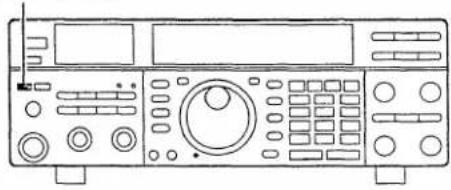
② Push [BK-IN/VOX] on the front panel IN.
③ While speaking into the microphone, rotate [VOX GAIN] clockwise until the transceiver is transmitting.
④ Adjust the [DELAY] control for a convenient interval before returning to receive.
⑤ If the receive audio from the speaker toggles to transmit, adjust the [ANTI-VOX] control to the point where it has no effect.
Meter function
Push the [METER] switch once to indicate the meter function, then push it a 2nd time or more to change the function in sequence.
| POWER "Po" | Indicates relative RF output power in watts. |
| SWR "Swr" | Indicates the antenna SWR. The SWR is detected before the signal enters the antenna tuner. Therefore, when you need true SWR, turn the antenna tuner OFF. To check the antenna SWR, at least 30 W is necessary. |
| ALC "ALC" | Indicates the ALC level. When the meter movement shows the input signal level exceeds the allowable level, the ALC limits the RF power. In such cases, reduce the [MIC GAIN] control. |
PRACTICAL EXAMPLE
When you receive a pile-up and you want to start split frequency operation to simplify picking out stations:
① Announce your receive frequency; then, push and hold [SPLIT] for 1 sec.
- The sub VFO frequency is equalized to the main VFO frequency and they appear with "SPLIT."
② Rotate the main dial to set your receive frequency in the main VFO.
③ After you catch one of the calling stations' call signs, push and hold the PTT switch to respond.
- While pushing [XFC], you can monitor your transmit frequency.
[BK-IN/VOX]
natural_image
Line drawing of a vintage electronic device with control panel and buttons (no text or symbols)![GAIN] VOX] [DELAY]](/content/2026/05/862926/images/8264a640601270557c8bd7e7ae8d7f03aa84e966871ed6af28621e483df73292.jpg)

natural_image
Simple line drawing of two 3D geometric shapes resembling cylinders or blocks, no text or symbols present.Power meter
SWR meter

ALC meter
4 FUNCTION OPERATIONS
PBT operation
The PBT function electronically narrows the receiver's IF passband width to reduce interference.
The [PBT] control should normally be set to the center position when there is no interference.
NOTE: When PBT is used, the audio tone may be changed.
PBT OPERATION EXAMPLE

Notch operation
The notch function attenuates a part of the received signal at the set filtering frequency to eliminate unwanted tones. The notch function acts in all operating modes including FM, as an AF type notch is included with the IC-736/738.
The notch function should be turned OFF when there are no unwanted tones.
This notch has a characteristic of max. 20 dB attenuation at the center of your set AF frequency.
NOTCH OPERATION EXAMPLE
Moving the filtering frequency to low.
Center
Moving the filtering frequency to high.
Notch OFF



natural_image
Simple curved line drawing resembling a dome or arch shape (no text or symbols)Set mode operation
The set mode is used for programming infrequently changed values or conditions of functions. This transceiver's set mode has 15 items.
- Set mode operation
① Push OUT [POWER] to turn power OFF.
② While pushing [FREQ-INP] and [ENT], push [POWER] IN to turn power ON.
- Now the set mode is selected and one of its items appears.
③ Push [UP] or [DOWN] several times until the desired item appears.
④ Rotate the main dial to set the values or conditions for the selected item.
⑤ Repeat steps ③ and ④ to set other items.
⑥ After all desired items are set, push [POWER] OUT to turn power OFF.
⑦ Push [POWER] IN to turn power ON.
- Now the set values or conditions are effective.
When you want to set an item to its default setting (initialized condition), push [CLEAR] after selecting the desired item.
![[POWER] [FREQ-INP] [ENT]](/content/2026/05/862926/images/b5a34bdac0f8f100c7565b261951431bf4f416e462668e6b712a08e42869dffb.jpg)
[DISPLAY EXAMPLE IN THE SET MODE]

(1) Confirmation beep "bEEP"
A beep sounds each time a switch is pushed for confirmation. This confirmation beep can be turned OFF for silent operation.

Confirmation beep ON (default)

Confirmation beep OFF
(2) Auto tuning step function "tS-Aut"
When selecting AM or FM, the quick tuning step is automatically selected by the auto tuning step function. This function can be turned OFF if desired.

Auto tuning step function ON (default)

Auto tuning step function OFF
4 FUNCTION OPERATIONS
(3) Filter selection "n-FIL"
The transceiver is designed to emit audio even when CW-N mode is selected and no filter is installed.
When a filter is installed, this selection is necessary, otherwise, the CW-narrow filter is not effective.
No optional CW-narrow filter is installed: Select "OFF".
Only a 9 MHz filter (FL-100 or FL-101) is installed: Select “-9-”.
Only a 455 kHz filter (FL-52A or FL-53A) is installed: Select "455".
Both 9 MHz and 455 kHz filters are installed: Select “-9-455”.

No filter installed (default)

9 MHz filter installed

455 kHz filter installed

Both 9 MHz and 455 kHz filters installed
(4) Scan resume "SC-rES"
You can select scan resume or cancel for when an operating scan detects a signal.
When selecting resume (ON), the scan pauses 10 sec. on the detected signal, then it resumes. If the signal disappears while the scan is paused, the scan resumes 2 sec. later to search for other signals.
When selecting cancel (OFF), the scan stops and turns OFF after detecting a signal.

Resume (default)

Cancel
(5) Scan speed "SC-SPd"
You can select high or low for the scanning speed.

High speed (default)

Low speed
(6) Microphone up/down speed "UP-SPd"
When you push and hold the microphone [UP]/[DOWN] switches, you can change the frequency continuously.
You can select high or low speed tuning for the microphone [UP]/[DOWN] switches.

High speed (default)

Low speed
(7) Memo pad capacity "PAd-CH"
You can select the number of memo pads, 5 or 10, for your convenience.
5
PRd-CH 7
5 memo pads (default)
10
PRd-CH 7
10 memo pads
(8) Antenna switch "Ant-SEL"
You can set the antenna connector selection to automatic, manual or non-selection (when using 1 antenna only).
When "Aut" is selected, the [ANT] switch is activated and the band memory memorizes the selected antenna. See p. 36 for details.
When "on" is selected, the [ANT] switch is activated and selects an antenna manually.
When "oFF" is selected, the [ANT] switch is not activated and does not function.
R_{L}
Ant-SEL B
Antenna switch Auto (default)
G F
RanE-SEL 8
Antenna switch ON
OFF
Ran-SEL 8
Antenna switch OFF
(9) Automatic tuner start "Aut-tun"
You can select the internal tuner operating condition. The tuner has an automatic start capability which starts tuning (the [TUNER] switch is turned ON automatically) if the SWR is higher than 1.5 - 3.
When "oFF" is selected, the tuner remains OFF even when the SWR is poor. (1.5 - 3)
When "on" is selected, automatic tune starts even when the tuner is turned OFF.

NOTE: Even when "on" is selected, automatic tune does not start for the IC-736's 50 MHz band.
OFF
Aut-tun 9
Manual tuner ON/OFF (default)
07
Rut-tun 9
Automatic tune ON
(10) Quick split function "q-SPLIT"
The [SPLIT] switch can be used to set split frequency operation and VFO frequency equalization simultaneously.
When "on" is selected, the [SPLIT] switch equalizes VFO frequencies and operating modes when pushed and held.
When "oFF" is selected, the [SPLIT] switch does not equalize VFO frequencies and operating modes.
口口
9-SPL16 10
Quick split function ON (default)
□FF
9-5PL1t 10
Quick split function OFF
4 FUNCTION OPERATIONS
(11) Split lock cancel "SPLIT-L"
The dial lock function freezes the main dial functions at any time. However, only when the [XFC] switch is pushed — changing transmit frequency during split operation — can the lock function be canceled.
When "oFF" is selected, the main dial can be electronically locked at any time.
When "on" is selected, the main dial is activated for the purpose of changing split frequencies only, even when the dial lock is activated.

SPLIT-L11
Dial locked at any time (default)

SPLIT-L11
Dial activates for split frequency
(12) Cl-V address "Cl-Addr"
The IC-736 and IC-738 have the addresses of 40H (64) and 44H (68) as default values, respectively.
If you want to designate a different address for your IC-736/738, rotate the main dial to select the desired address in the range from 1H (1) to 7FH (127).
- Figures marked with an H are hexadecimals and bracketed figures are decimals.

C1 -Addr- 12
Address of 44H (IC-738 default)

C1 -Addr 12
Address of 7FH
(13) Cl-V baud rate "Cl-bAud"
Baud rate is the data transfer rate. The standard baud rate for the Icom CI-V is 1200 bps.
If you want to change the baud rate, rotate the main dial to select the desired baud rate from 300 bps, 1200 bps, 4800 bps or 9600 bps.
0 -bAud 13
1200 bps (CI-V standard, default)
C: -bRaud 13
9600 bps
(14) Cl-V transceive "Cl-trn"
Transceive operation is possible with the IC-736/738 connected to other Icom HF transceivers or receivers.
When "on" is selected, changing the operating frequency, operating mode, etc. on the IC-736/738 automatically changes those of connected transceivers (or receivers) and vice versa.

D-ten 14
Transceive ON (default)

0-ten 14
Transceive OFF
(15) CI-V operating frequency data length "CI-731"
When connecting the IC-736/738 to the IC-735 for transceive operation, you must change the operating frequency data length to 4 bytes.
When "oFF" is selected, the operating frequency data length is sent in 5 bytes.
When "on" is selected, the operating frequency data length is sent in 4 bytes.

01-73115
5 bytes of frequency data (default)

01-73115
4 bytes of frequency data
■ Band memory (for automatic antenna selection)
The IC-736 covers 0.5 – 30 and 45 – 60 MHz with 11 bands. The IC-738 covers 0.5 – 30 MHz with 10 bands. Each band has a band memory which can memorize a selected antenna (antenna 1 or antenna 2). When you change the operating frequency beyond a band, the previously used antenna is automatically selected for the new band. This function is convenient when you use 2 antennas.
To use the band memory, enter the set mode and confirm that "Aut" is selected as the antenna switch item (item number 8 on p. 34).

- When "oFF" is selected, the [ANT] switch does not function.
- When "on" is selected, you can use the [ANT] switch, however, band memory does not function. In this case, you must select an antenna manually.
When "Aut" is selected (default setting), the antenna tuner ON/OFF condition is consistent with the [ANT] switch.
| BAND | FREQUENCY RANGE | HAM BAND |
| 1 | 0.5- 1.59999 MHz | |
| 2 | 1.6- 1.99999 MHz | 160 m band |
| 3 | 2.0- 5.99999 MHz | 80 m band |
| 4 | 6.0- 7.99999 MHz | 40 m band |
| 5 | 8.0- 10.99999 MHz | 30 m band |
| 6 | 11.0- 14.99999 MHz | 20 m band |
| 7 | 15.0- 19.99999 MHz | 17 m band |
| 8 | 20.0- 21.99999 MHz | 15 m band |
| 9 | 22.0- 25.99999 MHz | 12 m band |
| 10 | 26.0- 30.00000 MHz | 10 m band |
| 11* | 45.0- 60.00000 MHz | 6 m band |
As all ham bands are separated as shown above, you can designate antenna 1 or antenna 2 individually for each ham band.
* The 6 m band is available for the IC-736 only.
[ANTENNA SWITCH SELECTION EXAMPLE]
Under the following conditions, "Aut" should be selected as the antenna switch set mode item.
- When you use 2 antennas.
- When you use an optional AH-3 antenna tuner for low bands and the internal tuner for high bands.
- When using a linear amplifier for the HF bands and a non-linear amplifier for the 50 MHz band. (IC-736 only)
Under the following conditions, "oFF" should be selected as the antenna switch set mode item.
- When using 1 antenna.
- When using the EX-627 HF AUTOMATIC ANTENNA SELECTOR for more than 3 antenna connections.
- When using an external antenna tuner.
Remote jack (CI-V) information
The IC-736/738 can be connected through an optional CT-17 CI-V LEVEL CONVERTER to a personal computer equipped with an RS-232C port. Icom Communication Interface-V (CI-V) controls frequency, operating mode, memory channels, etc.
Up to four Icom CI-V transceivers or receivers can be connected to a personal computer equipped with an RS-232C port.
See the page at left for setting the CI-V condition. (Set mode items No. 12 – No. 15)
To control the transceiver, see the CT-17 instruction manual or CI-V reference manual for details.

flowchart
graph TD
    A["9-15 V DC or AC adapter"] --> B["Personal computer"]
    A --> C["CT-17"]
    C --> D["IC-736/738"]
    C --> E["CI-V bus line"]
    B --> F["Computer"]
    C --> G["IC-736/738"]
    style A fill:#f9f,stroke:#333
    style B fill:#ccf,stroke:#333
    style C fill:#cfc,stroke:#333
    style D fill:#fcc,stroke:#333
    style E fill:#cff,stroke:#333
4 FUNCTION OPERATIONS
Antenna tuner operation
The internal automatic antenna tuner matches the IC-736/738 to the connected antenna automatically. Once the tuner matches an antenna, the variable capacitor angles are memorized as a preset point for each frequency range (100 kHz steps). Therefore, when you change the frequency range, the variable capacitors are automatically preset to the memorized point.
TUNER OPERATION
• For the HF band:
Push the [TUNER] switch to turn the tuner ON. The antenna is tuned automatically when the antenna SWR is higher than 1.5:1.
Push [TUNER]

natural_image
Line drawing of a car dashboard with control panels and buttons (no text or symbols)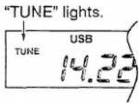
- When the tuner is OFF, "THRU" appears.
CAUTION: NEVER transmit with the tuner ON when no antenna is connected. This will damage the transceiver. Be careful of the [ANT] switch selection.

The internal antenna tuner in the IC-736 can match both HF and 50 MHz bands. However, operation is different for the HF and 50 MHz bands.
• For the 50 MHz band (IC-736 only):
Push and hold the [TUNER] switch to tune the antenna.
If "TUNE" blinks slowly while transmitting, push and hold [TUNER] again to re-tune the antenna.
When "TUNE" blinks,

push and hold [TUNER].
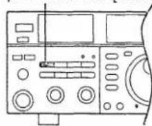
natural_image
Line drawing of a car dashboard with control panels and buttons (no text or symbols)• The "TUNE" indicator blinks for 10 sec. while SWR is poor.
- If the [TUNER] switch is not pushed within 10 sec., the tuner is automatically turned OFF, then “ ^THRU ” is selected.
MANUAL TURING
During SSB operation on HF bands at low voice levels, the internal tuner may not be tuned correctly. In such cases, manual tuning is helpful.
Push and hold the [TUNER] switch for 1 sec., to start manual tuning.
- CW mode is selected, a side tone is emitted, and "TUNE" blinks, then, the previous mode is selected.
Push and hold [TUNER]
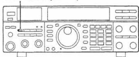
natural_image
Line drawing of a vintage electronic device with control panel and buttons (no text or symbols)If the tuner cannot reduce the SWR to less than 1.5:1 after 20 sec. of tuning, check the following:
• the [ANT] switch selection.
- the antenna connection and feedline.
- the antenna SWR (p. 30).
Through inhibit (HF bands only)
The internal tuner has a through inhibit condition. When selecting this condition, the tuner can be used at poor SWR's. In this case, automatic tuning in the HF bands activates only when exceeding SWR 3:1. Therefore, manual tuning is necessary each time you change the frequency. Although termed "through inhibit," the tuner will be "THROUGH" if the SWR is higher than 3:1 after tuning. (p. 50)
CONVENIENT
• Tuner sensitive condition (HF bands only) If you require critical tuning at any time during transmission, select the tuner sensitive condition. See p. 50 for selection.
• Automatic tuner start (HF bands only) If you require to turn OFF the tuner under conditions of VSWR 1.5 : 1 or less, use "automatic tuner on" and turn the tuner OFF. See p. 34 item (9) for turning the function ON and OFF.
Optional external tuner operation
AH-3 HF AUTOMATIC ANTENNA TUNER
The AH-3 matches the IC-736/738 to a long wire antenna more than 3 m/10 ft long (3.5 MHz and above) or more than 12 m/40 ft long (1.8 MHz and above).
• See p. 15 for the transceiver and AH-3 connection.
• See the AH-3 instruction manual for AH-3 installation and antenna connection details.
• See p. 60 for AH-3 and AH-2b details.
AH-3 setting example:

For outdoor operation

⚠ WARNING: HIGH VOLTAGE!
NEVER touch the antenna element while tuning or transmitting.
NEVER operate the AH-3 without an antenna wire. The tuner and transceiver will be damaged.
NEVER operate the AH-3 when it is ungrounded.
Transmitting before tuning or transmitting while the "THRU" indicator lights may damage the transceiver.

NOTE: When connecting the AH-3, the antenna connector assignments are [ANT 2] for the internal tuner and [ANT 1] for the AH-3.
NOTE for IC-736: The AH-3 can be used for HF bands only and cannot be used for the 50 MHz band.
AH-3 operation
Tuning is necessary for each frequency. Be sure to re-tune the antenna before transmitting when you change the operating frequency, even a little bit.
① Select antenna 1 with the [ANT] switch if you connect the AH-3 and another antenna.
- "EXT" appears.

② Set the desired frequency in a ham band.
• The AH-3 will not operate on frequencies outside of ham bands.
③ Push and hold [TUNER] for 1 sec.
- "TUNE" blinks and "CW" appears while tuning.

natural_image
Line drawing of a vintage electronic device with control panel and buttons (no text or symbols)
④ - "TUNE" lights constantly when tuning is complete.

- "THRU" appears when the AH-3 cannot tune the connected antenna wire after 20 sec.

- When "THRU" appears, the AH-3 is bypassed and the antenna wire is connected to the antenna connector on the transceiver directly.
To bypass the AH-3 manually, push [TUNER].
c "THRU" appears.
ANTENNA TUNER OF THE IC-4KL or IC-2KL/IC-AT500
When using an external antenna tuner such as the IC-4KL's tuner or IC-AT500 with a linear amplifier, tune with the external antenna tuner, while the internal tuner is turned OFF. After tuning is completed, turn the internal tuner ON, if required.
See the instruction manual included with each antenna tuner for their respective operations.
5 MEMORY CHANNELS
■ Memory channels
The transceiver has 101 memory channels. The memory mode is very useful for quickly changing to often-used frequencies.
Memory channels 1 - 89 can be programmed with one frequency and one mode each. Memory channels 90 - 99, P1 and P2 also have special functions described in the table below.
All 101 memory channels are tunable which means the programmed frequency can be tuned temporarily with the main dial, etc. in the memory mode.
| MEMORY CHANNEL | MEMORY CHANNEL NUMBER | CAPABILITY | TRANSFER TO VFO | OVER-WRITING | CLEAR |
| Regular memory channels | 1 – 89 | One frequency and one mode in each memory channel. | Yes | Yes | Yes |
| Split memory channels | 90 – 99 | Independent transmit and receive frequencies and operating modes in each channel for split operation. | Yes | Yes | Yes |
| Scan edge memory channels | P1, P2 | One frequency and one mode in each memory channel as scan edges for programmed scan. | Yes | Yes | No |
■ Memory channel selection
① Push [VFO/MEMO] to select the memory mode.
- "MEMO" appears.
② Rotate [M-CH] to select the desired memory channel.
- [UP] and [DN] on the microphone also select memory channels.
③ To return to the VFO mode, push [VFO/MEMO] again.
[EXAMPLE]: Selecting memory channel 17.

Memory channel programming
Memory channel programming can be performed either in the VFO mode or in the memory mode.
- Programming in the VFO mode
① Set the desired frequency and operating mode in the VFO mode.
② Rotate [M-CH] to select the desired memory channel to be programmed.
- To confirm the memory channel contents, push [VFO/MEMO]; then push [VFO/MEMO] again to return to the VFO mode.
- “BLANK” appears if the selected memory channel is a blank channel (and does not have contents).
③ Push and hold [MW] for 1 sec. to program the displayed frequency and operating mode into the memory channel.
To check the programmed contents, push [VFO/MEMO] to select the memory mode.
[EXAMPLE]: Programming 7.088 MHz/LSB into memory channel 12.
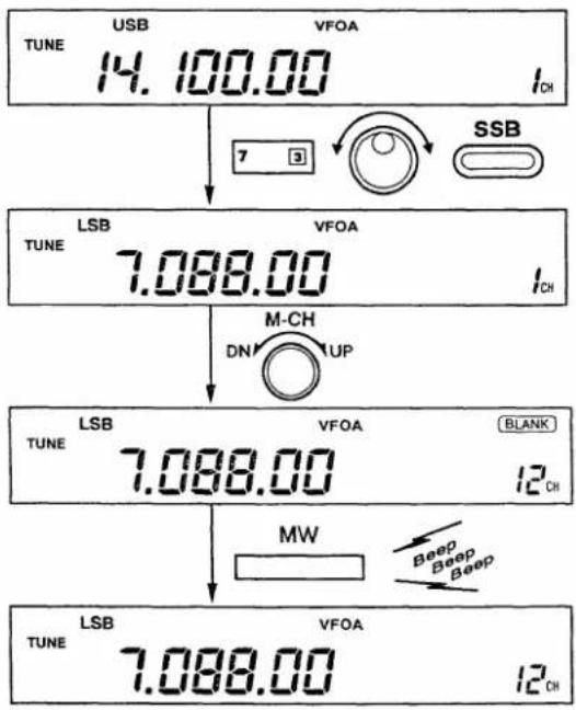
• Programming in the memory mode
① Select the desired memory channel to be programmed with [M-CH] in the memory mode.
② Set the desired frequency and operating mode in the memory mode.
- To program a blank channel, use direct frequency entry with the keypad. (p. 21)
③ Push and hold [MW] for 1 sec. to program the displayed frequency and operating mode into the memory channel.
[EXAMPLE]: Programming 21.280 MHz/USB into memory channel 18.


Frequency transferring
The frequency and operating mode in the memory mode can be transferred to the VFO mode.
The frequency tranferring can be performed in either the VFO mode or in the memory mode.
• Transferring in the VFO mode
This is useful for transferring programmed contents to VFO.
① Select VFO A or VFO B with [A/B] in the VFO mode.
② Select a memory channel with [M-CH].
- To confirm the memory channel contents, push [VFO/MEMO]; then push [VFO/MEMO] again to return to the VFO mode.
- “BLANK” appears if the selected memory channel is a blank channel (and does not have contents). In this case transferring is impossible.
③ Push and hold [M▶VFO] for 1 sec. to transfer the frequency and operating mode.
- Transferred frequency and operating mode appear on the display.
TRANSFERRING EXAMPLE IN THE VFO MODE
Operating frequency : 21.320 MHz/USB (VFO A) Contents of MEMO 16 : 14.020 MHz/CW

• Transferring in the memory mode
This is useful for transferring frequency and operating mode while operating in the memory mode.
NOTE: When you have changed the frequency or operating mode in the selected memory channel:
- Displayed frequency and mode are transferred.
- Programmed frequency and mode are not transferred, and they remain in the memory channel.
① Select a memory channel with [M-CH] in the memory mode.
- And, set the frequency or operating mode if required.
② Push and hold [M>VFO] for 1 sec. to transfer the frequency and operating mode.
• Displayed frequency and operating mode are transferred to the previously used VFO.
③ To return to the VFO mode, push [VFO/MEMO].
TRANSFERRING EXAMPLE IN THE MEMORY MODE
Operating frequency : 14.028 MHz/CW (MEMO 19)
Previously used VFO : VFO A


Memory clearing
Any unnecessary memory channels can be cleared. The cleared memory channels become blank channels.
![USB MEMO TUNE 34.980.00 22 Ch TUNE MEMO [BLANK] 22 Ch](/content/2026/05/862926/images/8d637e594ca2acf82bca1a7cb7234916cfdeb75489eccb264c839d37b301fbd7.jpg)
① Select the memory mode with [VFC/MEMO].
② Select a memory channel to be cleared with [M-CH].
③ Push and hold [CLEAR] to clear the contents.
- The programmed frequency and operating mode disappear and "BLANK" appears.
④ To clear other memory channels, repeat steps ② and ③.
Scan edge memory channels
Memory channels P1 and P2 are scan edge memory channels. These memory channels are used to program scan edge frequencies for programmed scan. (p. 46)
Scan edge memory channels can be programmed for 1 frequency and 1 operating mode like regular memory channels. However, memory clearing is impossible. Only overwriting is possible for scan edge memory channels.
- Scan edge memory channel selection
① Push [VFO/MEMO] to select the memory mode.
• "MEMO" appears.
② Rotate [M-CH] to select the desired scan edge memory channel.
• [UP] and [DN] on the microphone also select memory channels.
③ To return to the VFO mode, push [VFO/MEMO] again.
You can transmit and receive using the programmed frequency and operating mode in the scan edge memory channels.
[EXAMPLE] : Selecting scan edge memory channel P1.

- Scan edge memory channel programming
A scan edge memory channel can be programmed in either the VFO or memory mode the same way as regular memory channel programming.
Following is an example of programming 28.000/28.050 MHz into scan edge memory channels P1/P2 in the VFO mode.
① Set 28.000 MHz in the VFO mode.
- An operating mode can also be programmed, however, the programmed operating mode does not affect programmed scan.

② Rotate [M-CH] to select the scan edge memory channel P1.

③ Push and hold [MW] for 1 sec. to program 28.000 MHz into the scan edge memory channel P1.

④ Change the displayed frequency to 28.050 MHz.

⑤ Rotate [M-CH] to select the other scan edge memory channel, P2.

⑥ Push and hold [MW] for 1 sec. to program 28.050 MHz into the scan edge memory channel P2.

To check the programmed contents, push [VFO/MEMO] to select the memory mode, then select P1 or P2 with [M-CH].
Split memory channels (for accessing a repeater)
Memory channels 90 - 99 are split memory channels and can be programmed for both transmit and receive frequencies and operating modes.
These memory channels are especially useful for repeater operation.
- Split memory channel selection
Select a memory channel in the range between 90 - 99 with [M-CH] in the memory mode.
- "SPLIT" and 2 frequencies appear when split frequencies have been programmed in that channel.
- "SPLIT" does not appear when only 1 frequency has been programmed in that channel.
- "BLANK" appears when the selected memory channel is a blank channel (and does not have contents).
[SPLIT MEMORY CHANNEL DISPLAY EXAMPLE]

Split frequencies are programmed.

Simplex frequency is programmed.

No frequency is programmed.
- Split memory channel programming
2 frequencies can be programmed in a split memory channel when "SPLIT" and sub VFO frequencies are indicated in the function display.
Following is a programming example of 29.680 MHz (FM) for receiving and 29.580 MHz (FM) for transmitting in memory channel 95.
① Select VFO mode with [VFO/MEMO].
- Both VFO A and VFO B can be used.

② Set 29.680 MHz (receive frequency).

③ Select FM mode with [FM/TONE].
- A subaudible tone can be programmed if you install an optional UT-30 PROGRAMMABLE TONE ENCODER. To program subaudible tone information, select "FM-T" by pushing [FM/TONE] twice.

④ Push and hold [SPLIT] for 1 sec.
- When the quick split function is OFF (p. 34), push [SPLIT]; then, push and hold [A = B] for 1 sec.
Sub VFO frequency and "SPLIT" appear.

⑤ While pushing [XFC] rotate the main dial to set the sub VFO frequency to 29.580 MHz (transmit frequency).

⑥ Select memory channel 95 with [M-CH] in the VFO mode.

⑦ Push and hold [MW] for 1 sec. to program the frequencies.

To check the programmed contents, push [VFO/MEMO] to select the memory mode.

- Split memory channel operation
When one of memory channels 90–99 is selected and the memory channel has been programmed with 2 frequencies, split frequency operation is automatically selected.
① Select the memory mode.
② Select a programmed split memory channel.
③ Transmit.
- “▶”appears while transmitting.
④ Return to receive.
- “▶” disappears while receiving.
When "FM-T" is programmed as an operating mode in the memory channel, a subaudible tone is automatically superimposed over your transmission.
- An optional UT-30 is necessary to generate a tone.
-To exchange the transmit and receive frequencies, push [A/B].
-To monitor the transmit frequency, push and hold [XFC].
-To turn the split frequency operation OFF temporarily, push [SPLIT].

[DISPLAY EXAMPLE]

- Split frequency transferring
The split frequency data in split memory channels can be transferred into a VFO. Transferring split memory channels is different in the VFO mode and the memory mode.
- When the selected memory channel has been programmed with only 1 frequency and 1 mode, transferring is the same as transferring from a regular memory channel. (p. 41)
IN THE MEMORY MODE
In the memory mode, 2 frequencies and modes with "SPLIT" information are transferred.
① Select a programmed split memory channel with [M-CH] in the memory mode.
② Push and hold [M▶VFO] for 1 sec. to transfer the frequencies and operating modes.
- Displayed frequencies, operating modes and "Split ON" are transferred to VFOs.
③ To return to the VFO mode, push [VFO].
[DISPLAY EXAMPLE]

IN THE VFO MODE
In the VFO mode, only the receive frequency and operating mode are transferred.
① Select VFO A or VFO B with [A/B] in the VFO mode.
② Select a programmed split memory channel with [M-CH].
- To confirm the memory channel contents, push [VFO/MEMO]; then push [VFO/MEMO] again to return to the VFO mode.
③ Push and hold [M▶VFO] for 1 sec. to transfer the receive frequency and operating mode.
[DISPLAY EXAMPLE]

NOTE: When the split function is turned ON before pushing [M▶VFO], you can transfer 2 frequencies and modes into the VFOs.
Scan types
The transceiver has 3 types of scan functions which provide tremendous scanning versatility at the touch of a few switches.
Select the scan which matches your operating needs.
PROGRAMMED SCAN
Repeatedly scans between two scan edge frequencies (scan edge memory channels P1 and P2).

flowchart
graph LR
    A["Scan edge P1 or P2"] -->|Scan| B["Scan edge P2 or P1"]
    B -->|Jump| A
This scan operates in the VFO mode.
MEMORY SCAN
Repeatedly scans all programmed memory channels.

flowchart
graph TD
    Mch1 --> Mch2
    Mch2 --> Mch3
    Mch3 --> Mch4
    Mch4 --> Mch5
    Mch5 --> Mch6
    Mch6 --> Mch7
    Mch7 --> Mch99
    Mch99 --> Mch1
    MCh1 --> Mch2
    MCh2 --> Mch3
    MCh3 --> Mch4
    MCh4 --> Mch5
    MCh5 --> Mch6
    MCh6 --> Mch7
    MCh7 --> Mch99
    MCh1 -->|SELECT| Mch2
    Mch2 -->|SELECT| Mch3
    Mch3 -->|SELECT| Mch4
    Mch4 -->|SELECT| Mch5
    Mch5 -->|SELECT| Mch6
    Mch6 -->|SELECT| Mch7
    Mch7 -->|SELECT| Mch99
    MCh1 -->| select| Mch1
    MCh2 -->| select| Mch2
    MCh3 -->| select| Mch3
    MCh4 -->| select| Mch4
    MCh5 -->| select| Mch5
    MCh6 -->| select| Mch6
    MCh7 -->| select| Mch7
    MCh8 -->| select| Mch8
    MCh8 -->| select| Mch99
    MCh8 -->| select| Mch10
    MCh8 -->| select| Mch11
    MCh8 -->| select| Mch12
    MCh8 -->| select| Mch13
    MCh8 -->| select| Mch14
    MCh8 -->| select| Mch15
    MCh8 -->| select| Mch16
    MCh8 -->| select| Mch17
    MCh8 -->| select| Mch18
    MCh8 -->| select| Mch19
    MCh8 -->| select| Mch20
    MCh8 -->| select| Mch21
    MCh8 -->| select| Mch22
    MCh8 -->| select| Mch23
    MCh8 -->| select| Mch24
    MCh8 -->| select| Mch25
    MCh8 -->| select| Mch26
    MCh8 -->| select| Mch27
    MCh8 -->| select| Mch28
    MCh8 -->| select| Mch29
    MCh8 -->| select| Mch30
    MCh8 -->| select| Mch31
    MCh8 -->| select| Mch32
    MCh8 -->| select| Mch33
    MCh8 -->| select| Mch34
    MCh8 -->| select| Mch35
    MCh8 -->| select| Mch36
    MCh8 -->| select| Mch37
    MCh8 -->| select| Mch38
    MCh8 -->| select| Mch39
    MCh8 -->| select| Mch40
This scan operates in the memory mode.
SELECT MEMORY SCAN
Repeatedly scans all select memory channels.

flowchart
graph TD
    Mch1 --> Mch2
    Mch2 --> Mch3
    Mch3 --> Mch4
    Mch4 --> Mch5
    Mch5 --> Mch6
    Mch6 --> Mch7
    Mch7 --> Mch99
    Mch99 --> Mch1
    MCh1 --> Mch2
    MCh2 --> Mch3
    MCh3 --> Mch4
    MCh4 --> BLANK
    Mch5 --> Mch6
    Mch6 --> Mch7
    Mch7 --> Mch99
    Mch99 --> Mch1
This scan operates in the memory mode.
Pre-operation
- Presetting
Program the memory channels before operating a scan as follows:
| SCAN TYPE | REQUIRED PRESETTING |
| PROGRAMMED SCAN | Program scan edge frequencies into scan edge memory channels P1 and P2. (p. 42) |
| MEMORY SCAN | Program desired scan frequencies into 2 or more memory channels. |
| SELECT MEMORY SCAN | Designate 2 or more memory channels as select memory channels with the [SEL] switch. |
- Scan resume ON/OFF
You can select the scan to resume or cancel when detecting a signal. Scan resume ON/OFF must be set before operating a scan. See p. 33 for ON/OFF setting and scan resume condition details.
- Squelch condition
Before starting a scan, open or close the squelch for the desired operation as described below:
| SCAN STARTS WITH | PROGRAMMED SCAN | MEMORY SCANS |
| SQUELCH OPEN | The scan continues until it is stopped manually, and does not pause even if it detects signals. | Scan pauses on each channel when the scan resume is ON; not applicable when OFF. |
| SQUELCH CLOSED | Scan stops when detecting a signal.If you set scan resume to "ON" in the set mode, the scan pauses for 10 sec. when detecting a signal, then resumes.When a signal disappears while scan is paused, scan resumes 2 sec. later. | |
- Scan speed
Scan speed can be selected from 2 levels, high or low, in the set mode. See p. 33 for details.
Programmed scan operation
① Select the VFO mode.
② Select the desired operating mode.
- The operating mode can also be changed while scanning.
③ Set [SQL] open or closed.
• See page at left for scan condition.
④ Push [SCAN] to start the scan.
- Decimal points blink while scanning.
⑤ When the scan detects a signal, the scan stops, pauses or ignores it depending on the resume setting and the squelch condition.
- During scan the [TS] switch can be used.
⑥ To cancel the scan, push [SCAN].
NOTE: If the same frequencies are programmed into the scan edge memory channels P1 and P2, programmed scan does not start.

③ Set squelch.
②Select operating mode.
[DISPLAY EXAMPLE DURING A SCAN]

Memory scan operation
① Select the memory mode.
② Close the squelch with [SQL].
③ Push [SCAN] to start the scan.
- Decimal points blink while scanning.
④ When the scan detects a signal, the scan stops or pauses depending on the scan resume setting.
⑤ To cancel the scan, rotate the main dial, or push [SCAN].
NOTE: 2 or more memory channels must be programmed for memory scan to start.

Select memory scan operation
① Select the memory mode.
② Close the squelch with [SQL].
③ Push [SCAN] to start the memory scan.
• Decimal points blink while scanning.
④ Push [SEL] to activate the select memory scan.
• "SELECT" continuously lights during select memory scan.
⑤ When the scan detects a signal, the scan stops or pauses depending on the scan resume setting.
⑥ To cancel the scan, rotate the main dial, or push [SCAN].
NOTE: 2 or more memory channels must be designated as select memory channels for select memory scan to start.

SMS: Select memory scan MS: Memory scan
[DISPLAY EXAMPLE DURING A SCAN]
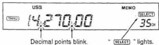
7 MAINTENANCE AND ADJUSTMENT
■ Frequency calibration (approximate)
A very accurate frequency counter is required to calibrate the frequency of the IC-736/738. However, a rough check may be performed by receiving radio station WWV, or other standard frequency signals.
The calibration can be performed in each operating mode. The calibration range is ±9.999 kHz in 1 Hz steps (or 10 Hz steps when the 1 Hz indicator is turned OFF.).

CAUTION: Your transceiver has been thoroughly adjusted and checked at the factory before being shipped. You should not calibrate frequencies, except for special reasons.
① Set the displayed frequency to 10.000.00 MHz/USB or 15.000.00 MHz/USB to receive a standard frequency station.
- Other standard frequencies can also be used.
② Turn the transceiver power OFF.
③ While pushing and holding [RIT] and [ENT], turn power ON.
![[POWER] [ENT] [RIT]](/content/2026/05/862926/images/3b620d33acefe1dffa3ca22723dc6470f3c2d59628e1681beb109e99a1cc0085.jpg)
④ Release [RIT] and [ENT].
- "RIT" and "ΔTX" blink, and the calibration mode is selected.

⑤ Rotate the [RIT/ΔTX] control for a zero beat.
- Push and hold [TS] for 1 sec. to select 1 Hz calibration.
⑥ Push and hold [MW] for 1 sec. to memorize the USB calibration value.
⑦ Push [SSB] to select LSB.
⑧ Rotate the [RIT/ TX] control for a zero beat.
⑨ Push and hold [MW] for 1 sec. to memorize the LSB calibration value.
⑩ Push [CW/N] to select CW.
⑪ Rotate the [RIT/ΔTX] control for a zero beat.
⑫ Push and hold [MW] for 1 sec. to memorize the CW calibration value.
⑬ Turn the power OFF then ON to exit the calibration mode.
- "RIT" and "△TX" disappear.

- Calibration for AM or FM can also be performed, but an accurate frequency counter is necessary.
- The calibrated values are effective after exit from the calibration mode.
- To clear the calibrated values, push and hold [RIT] for 1 sec. in the calibration mode.
- The calibrated values are cleared and all values return to their default settings.
Main dial brake adjustment
The tension of the main dial may be adjusted to suit your preference.
The brake adjustment screw is located on the lower left side of the main dial. See the figure at right.
Turn the brake adjustment screw clockwise or counterclockwise to obtain a comfortable tension level while turning the main dial continuously and evenly in one direction.

■ Fuse replacement (for the IC-736)
If a fuse blows or the transceiver stops functioning, try to find the source of the problem, and replace the damaged fuse with a new, rated fuse.
⚠ WARNING: DISCONNECT the AC power cable from the transceiver when replacing a fuse.
Use one of the following fuses to match the voltage of the AC outlet:
100 – 120 V versions ..... 10 A
220 - 240 V versions ..... 5 A (High breaking
capacity fuse)
⚠ WARNING: NEVER use non-rated fuses. Non-rated fuses could cause a fire. Use appropriate fuses as described above.
AC FUSE REPLACEMENT

natural_image
Technical line drawing of a mechanical assembly with multiple components and a central rotating element (no text or symbols)When removing the fuse, push the fuse holder, then set the gutter to the vertical position.
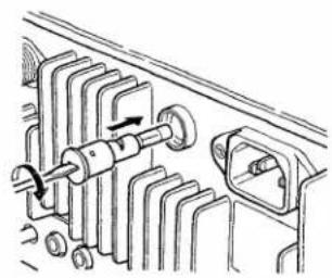
natural_image
Technical line drawing of a mechanical assembly with gears and a shaft (no text or symbols)When installing the fuse, set the gutter to the vertical position, then install the fuse. Rotate the fuse holder clockwise to set to the horizontal position.
■ Fuse replacement (for the IC-738)
If a fuse blows or the transceiver stops functioning, try to find the source of the problem, and replace the damaged fuse with a new, rated fuse.
CAUTION: DISCONNECT the DC power cable from the transceiver when changing a fuse.
The IC-738 has 2 types of fuses installed for transceiver protection.
- DC power cable fuses ...... FGB 20 A
- Circuitry fuse ...... FGB 125 V, 4 A
DC POWER CABLE FUSE REPLACEMENT

CIRCUITRY FUSE REPLACEMENT
The 12 V DC from the DC power cable is applied to all units in the IC-738, except for the power amplifier, through the circuitry fuse. This fuse is installed under the top cover.
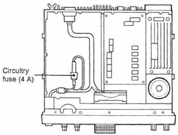
7 MAINTENANCE AND ADJUSTMENT
■ Opening the transceiver's case
Follow the case and cover opening procedures shown here when you want to install an optional unit or adjust the internal units, etc.
⚠ WARNING: DISCONNECT the AC or DC power cable from the transceiver and wait a few minutes before performing any work on the transceiver.
• To see the Main and PLL units
① Remove 10 screws from the transceiver's top and 4 screws from the sides, then lift up the top cover.
② Turn the transceiver upside down.
③ Remove 5 screws from the bottom cover, then lift up the bottom cover.
④ Now you can see the Main and PLL units.
• To see the Filter and Reg units (IC-736 only)
① Open the top and bottom covers as shown at left.
② Turn the transceiver upside up.
③ Remove 13 screws from the internal shield cover, then lift up the cover.
④ Now you can see the Filter and Reg units.
• The PA unit is located under the Filter unit.

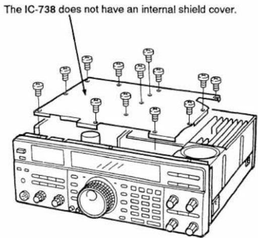
LCD dimmer adjustment
The LCD dimmer can be adjusted to your preference.
① Remove the top cover.
⚠ WARNING for the IC-736: DO NOT remove the internal shield cover as it houses HIGH VOLTAGE when turning power ON.
② Turn the transceiver power ON.
③ Adjust the trimmer potentiometer as shown in the diagram at right.
④ Replace the top cover.
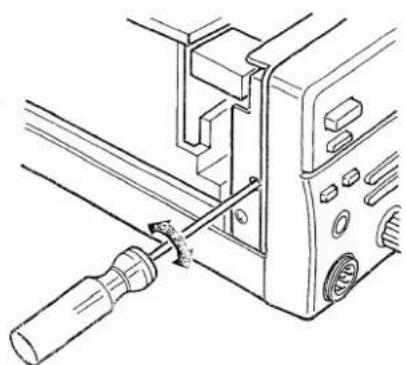
natural_image
Technical line drawing of a mechanical assembly with a screwdriver inserted (no text or symbols)AC power voltage selection (for the IC-736)
WARNING: DISCONNECT the AC power cable from the transceiver and wait a few minutes before performing AC power voltage selection.
① Remove the top cover and internal shield cover as shown on the page at left.
② Unplug the cable as shown in the diagram at right, then connect it to the desired voltage position.
⚠ WARNING: DO NOT forget to change the AC fuse when you change the AC input voltage (see p. 48 for appropriate fuse). An incorrect fuse may pose a fire hazard.

Tuner operating condition
The internal antenna tuner has 3 operating conditions for HF band operation. Select a suitable condition according to your antenna system.
① Remove the top and bottom covers as shown on the page at left.
② Set the tuner switches to the desired positions.
| SW | Position | Operation |
| S1 | A(Default) | The tuner operating condition is set by S2 described below. |
| B | THROUGH INHIBITThe tuner tunes the antenna even when the antenna has poor SWR (up to VSWR 3:1 after tuning). In this case, manual tuning is necessary each time you change the frequency although the tuner automatically starts tuning when the VSWR is higher than 3:1. This setting is called “THROUGH INHIBIT,” however, the tuner is set to “THROUGH” if the VSWR is higher than 3:1 after tuning. | |
| S2 | C | TUNER SENSITIVE CONDITIONThe tuner tunes each time you transmit (except SSB mode). Therefore, the lowest SWR is obtained at any given time.For the SSB mode, the same condition as the “D” position. |
| D(Default) | NORMAL CONDITIONThe tuner tunes when the SWR is higher than 1.5:1. Therefore, the tuner activates only when tuning is necessary. |
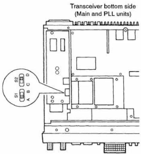
7 MAINTENANCE AND ADJUSTMENT
■ PA idling current adjustment (for the IC-738)
See p. 58 for the IC-736.
The PA unit operates with a linear amplifier and requires some idling current to flow through the driver and final transistors to obtain bias voltage.
① Preparation:
[POWER] : OFF
[MIC] : Max. counterclockwise
[RF PWR] : Max. counterclockwise
Microphone : Disconnect
Ammeter : 500 mA range
② Remove the top cover. (p. 49)
③ Remove the 8 screws and 2 antenna connectors, then open the Filter unit as shown in Fig. 1.
REMOVING THE FILTER UNIT

(Fig. 1)
④ Unsolder points indicated by *1 and *2 in Fig. 2.
⑤ Properly connect test leads to points. See figure 3 for the driver amplifier and figure 4 for the final amplifier adjustments.
⑥ Turn transceiver power ON.
⑦ Push [SSB] to select LSB or USB.
⑧ Push [TRANSMIT] IN to transmit.
⑨ Adjust the idling current as following table:
| Adjustment item | Adjustment point | Values | Check point |
| Driver transistors | R11 | 300 mA | W29 |
| Final transistors | R18 | 500 mA | R28 and J9 |
⑩ Turn transceiver power OFF.
⑪ Re-solder the de-solder points.
⑫ Reassemble the transceiver.
IDLING CURRENT ADJUSTMENT

(Fig. 2)
Lithium backup battery
The transceiver has 1 lithium backup battery on the back side of the front panel (Logic unit) for retaining memory information. The usual life of the backup battery is approximately 5 years.
⚠ WARNING: DISCONNECT the AC or DC power cable and wait a few minutes before opening the top and bottom covers. See p. 49 for instructions on opening the case.
CAUTION: If a lithium battery is incorrectly replaced, it could explode. Replace with a CR-2032 or equivalent type.
When the backup battery on the logic unit is exhausted, the transceiver transmits and receives normally but cannot retain memory information.
BACKUP BATTERY LOCATION

Cleaning
If the transceiver becomes dusty or dirty, wipe it clean with a dry, soft cloth.
AVOID the use of strong chemical solvents such as thinner, benzine or alcohol to clean the cabinet, as these may damage the transceiver's surfaces.
8
OPTIONS INSTALLATION
CW narrow filters
The transceiver has a CW-Narrow mode to provide better S/N (signal-to-noise ratio), or to reject nearby interference. To use the CW-Narrow mode, optional CW filters are necessary.
1 or 2 CW narrow filters can be installed in the IF circuits.
- FL-100 or FL-101 can be installed in the 2nd IF circuit.
- FL-52A or FL-53A can be installed in the 3rd IF circuit.
When 2 filters are installed, the passband width characteristic acquires more shape than when 1 filter is installed, moreover, the PBT function can be used in the CW-Narrow mode with 2 filters.
| Filter | Passband width | Center frequency |
| FL-52A | 500 Hz/−6 dB | 455 kHz (3rd IF) |
| FL-53A | 250 Hz/−6 dB | 455 kHz (3rd IF) |
| FL-100 | 500 Hz/−6 dB | 9.0106 MHz (2nd IF) |
| FL-101 | 250 Hz/−6 dB | 9.0106 MHz (2nd IF) |
If you install 2 filters, the same passband width CW narrow filters should be installed.
- If you want to use a 500 Hz passband width for CW-Narrow mode, you should install FL-100 and FL-52A.
- If you want to use a 250 Hz passband width for CW-Narrow mode, you should install FL-101 and FL-53A.
If you want to install 1 filter, a 3rd IF filter (FL-52A or FL-53A) is recommended because of the filters' characteristics.
① Remove the top and bottom covers. (p. 49)
② Insert the filter(s) at the proper position. The locations are shown in the figures below.
- The FL-52A or FL-53A must be installed in the proper direction.
- The FL-100 or FL-101 work regardless of the direction they are installed in.
③ Replace the top and bottom covers.
FL-52A or FL-53A installation
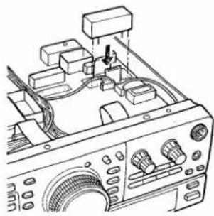
natural_image
Technical line drawing of an electronic device with ports and wiring (no text or symbols)FL-100 or FL-101 installation
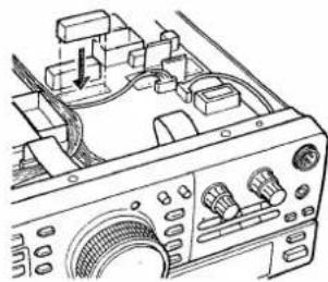
natural_image
Technical line drawing of an electronic instrument with no visible text or symbols
FILTER SELECTION
After the filter(s) are installed, select the filter condition in the set mode. (p. 33) If this is not correctly set, received signals do not pass through the filter(s) even when CW-Narrow mode is selected.
UT-30 PROGRAMMABLE TONE ENCODER UNIT
The UT-30 has 38 programmable tones available.
![UT-30 [KEY] jack J33](/content/2026/05/862926/images/c6f8ca2bc620f3937d6ca8f3cbe5056dec6f74c8c6cddf468261fd29d9210d56.jpg)
Prior to unit installation, tone frequency programming is necessary for the UT-30.
① Remove the top and bottom covers. (p. 49)
② Attach the supplied double-sided tape to the UT-30.
③ Attach the UT-30 to the [KEY] connector and connect the plug to J33 as shown in the diagram.
④ Replace the top and bottom covers.
CR-282 HIGH-STABILITY CRYSTAL UNIT
By replacing the original crystal unit with this unit, the total frequency stability of the transceiver will be improved.


natural_image
Technical line drawing of a mechanical component with tool tips, no visible text or symbolsDesolder points for removal.
CR-282 frequency stability: ± 0.5 ppm
$$ (- 3 0 ^ {\circ} \mathrm{C} \text { to } + 6 0 ^ {\circ} \mathrm{C}; $$
$$ - 2 2 ^ {\circ} \mathrm{F} \text { to } + 1 4 0 ^ {\circ} \mathrm{F}) $$
① Remove the top and bottom covers (p. 49).
② Remove 6 screws from the PLL unit then turn over the PLL unit to see the reverse side.
③ Unsolder the leads of the previously installed crystal, then remove the crystal.
• Use a desoldering braid.
④ Unsolder the 4 positions on the PLL unit where the CR-282 will be installed.
⑤ Install the CR-282 in the PLL unit, paying attention to orientation.
- Symbols on the bottom of the CR-282 must be identically matched with symbols on the P.C. board.
⑥ Bend the leads of the CR-282 at the foil side of the P.C. board and solder them as shown in figure 2 at left.
⑦ Trim the leads even with the solder points.
⑧ Replace the PLL unit and covers.
After changing the crystal unit, frequency adjustment is necessary with C79 on the PLL unit.
- Ask your Icom Dealer or Icom Service Center for details.
NOTE: The CR-282 is an oven-heat-type crystal unit, and the specified frequency stability described above is guaranteed 1 min. after power ON.
MB-49 MOBILE MOUNTING BRACKET
The MB-49 mobile mounting bracket allows you to install the transceiver in your vehicle, boat, etc.
NOTE: The IC-736 requires an AC power source for operation.
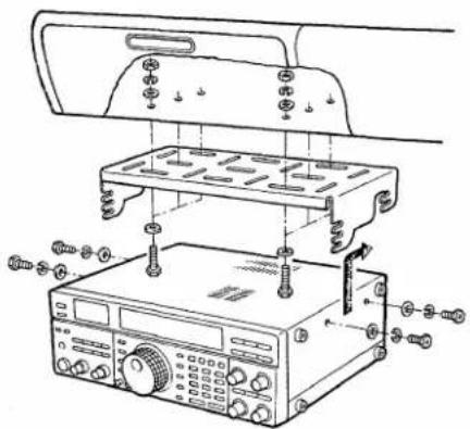
① Select a location which can support the weight of the transceiver and that does not interfere with operation of the vehicle.
② Align the MB-49 with the chosen location; then, mark the required hole positions for bracket attachment.
③ Remove the MB-49; then, drill the holes.
④ Fix the bracket with the supplied bolts, nuts and washers.
⑤ Attach the transceiver to the bracket with the 4 sets of supplied bolts and washers.
- You can select one of six angles by setting the 4 side bolt's positions on the MB-49.

natural_image
Technical line drawing of a mechanical component with no visible text or symbolsThe following chart is designed to help you correct problems which are not equipment malfunctions.
If you are not able to locate the cause of a problem or solve it through the use of this chart, contact your nearest Icom Dealer or Service Center.
| PROBLEM | POSSIBLE CAUSE | SOLUTION | REF. | |
| POWER SUPPLY | Power does not come on when the [POWER] switch is pushed. | Fuse is blown.Internal breaker is thrown.(IC-736 only) | Disconnect any connections, then replace the fuse with a spare one.WARNING: NEVER use a non-rated fuse. This could cause a fire.Turn power OFF then ON again. The internal breaker should be reset. If the breaker is thrown again, the transceiver may need maintenance. | p. 48- |
| RECEIVE | No sound comes from the speaker. | Volume level is too low.The squelch is closed.The [RF GAIN] control is rotated counterclockwise.The transceiver is in the transmitting condition.An external speaker or headphones are connected. | Rotate [AF] clockwise to obtain a suitable listening level.Rotate [SQL] counterclockwise to open the squelch.Rotate [RF GAIN] clockwise. The recommended position is max. clockwise.Push [TRANSMIT] OUT or check the SEND line of an external unit, if connected.Check the external speaker or head-phone plug connection.Check the speaker ON/OFF switch or speaker A/B switch, when an optional SP-20 EXTERNAL SPEAKER is in use. | p. 18p. 18p. 3p. 1pgs. 12, 23- |
| Sensitivity is low. | The antenna is not connected properly.The antenna feedline is cut or shorted.The antenna for another band is selected.The antenna is not properly tuned when an optional antenna tuner is connected.The attenuator function is activated. | Reconnect to the antenna connector.Check the feedline and correct any improper conditions.Select an antenna suitable for the operating frequency.Push and hold [TUNER] to manually tune the antenna.Push [ATT] to turn the function OFF. | p. 12-p. 2pgs. 37, 38p. 2 | |
| Receive audio is distorted. | The operating mode is not selected correctly.PBT function is activated. | Select a suitable operating mode.Set [PBT] to the center position. | p. 4pgs. 6, 31 | |
| Receive signal is distorted with strong signals. | Noise blanker function is activated.Preamp is activated. | Push [NB] to turn the function OFF.Push [PREAMP] to turn the function OFF. | p. 2p. 2 | |
| Antenna switch, ([ANT]), does not function. | The antenna switch has not been activated. | Set the antenna switch in the set mode to "on" or "Aut." | p. 34 | |
| TRANSMIT | Transmitting is impossible. | The operating frequency is not set to a ham band. | Set the frequency to a ham band. | p. 21 |
| Output power is too low. | [RF PWR] is set too far counterclockwise.[MIC] is set too far counterclockwise.The antenna is not connected properly.The antenna feedline is cut or shorted.An antenna for another band is selected.The antenna is not properly tuned. | Rotate [RF PWR] clockwise.Set [MIC] to a suitable position.Reconnect the antenna and check the [ANT] switch position.Check the feedline and correct any improper conditions.Select an antenna suitable for the operating frequency.Push and hold [TUNER] to manually tune the antenna. | p. 3pgs. 2, 25p. 12-p. 2pgs. 37, 38 | |
| No contact possible with another station. | RIT function is activated.ΔTX function is activated.Split function is activated. | Push [RIT] to turn the function OFF.Push [ΔTX] to turn the function OFF.Push [SPLIT] to turn the function OFF. | p. 5p. 5pgs. 4, 29 | |
| Repeater cannot be accessed. | Split function is not activated.An incorrect transmit frequency is set.Subaudible tone encoder is turned OFF when trying to access a repeater which requires a tone for access.Programmed subaudible tone frequency is wrong. | Push [SPLIT] to turn the function ON.Set the proper frequencies into VFO A and B or into one of the split memory channels, 90–99.Push [FM/TONE] to select “FM-T.” (An optional UT-30 is necessary to generate the subaudible tone.)Reset the frequency referring to the UT-30 instruction manual. | pgs. 4, 29pgs. 29, 43pgs. 4, 43- | |
| Transmitted signals are distorted. | [MIC] is rotated too far clockwise.[COMP LEVEL] is rotated too far clockwise with the speech compressor ON. | Set [MIC] to a suitable position.Set [COMP LEVEL] to a suitable position. | pgs. 2, 25pgs. 7, 25 | |
| DISPLAY | The displayed frequency does not change properly. | The dial lock function is activated.The internal CPU has malfunctioned. | Push [LOCK] to deactivate the function.Perform CPU resetting.(While pushing and holding [CLEAR] and [ENT], turn power ON.) | p. 3p. 17 |
| SCAN | Programmed scan does not stop. | Squelch is open. | Set [SQL] to the threshold point. | p. 45 |
| Programmed scan does not start. | The same frequencies have been programmed in scan edge memory channels P1 and P2. | Program different frequencies into scan edge memory channels P1 and P2. | p. 42 | |
| Memory scan does not start. | 2 or more memory channels have not been programmed. | Program 2 or more memory channels. | p. 40 | |
| Select memory scan does not start. | 2 or more memory channels have not been designated as select channels. | Designate 2 or more memory channels as select channels for the scan. | p. 46 |
■ Main and PLL units
![R297 HF band 100 W set R597 50 MHz band 100 W set R349 FM deviation 3.5 kHz set [MIC]: center; 3 mV input R264 CW side tone level adj. R364 AM modulation 70% set [MIC]: center; 3 mV input R362 FM deviation 4.8 kHz set [MIC]: center; 30 mV input C79 Reference frequency adj. Antenna tuner PLL unit Main unit R130 S9 set (50 µV input) R131 S9 + 60 dB set (50 mV input) C400 USB 9.0130 MHz L128 CW-T 9.0106 MHz L127 LSB 9.0100 MHz R240 BFO check point Adjust the above point while checking this point. Space for an optional 455 kHz filter Space for an optional 9 MHz filter](/content/2026/05/862926/images/c6bb13bfd9be86f797f4e7f05de94ed19d571e58084016aab7311f8b39274540.jpg)
Filter and Reg units (IC-736)

Filter unit (IC-738)

11 SPECIFICATIONS
GENERAL
• Frequency coverage:
| Receive | 500 kHz – 29.995 MHz |
| 50 MHz – 54 MHz (IC-736 only) | |
| Transmit* | 1.800 – 1.999999 MHz |
| 3.500 – 4.000 MHz | |
| 7.000 – 7.300 MHz | |
| 10.100 – 10.150 MHz | |
| 14.000 – 14.350 MHz | |
| 18.068 – 18.168 MHz | |
| 21.000 – 21.450 MHz | |
| 24.890 – 24.990 MHz | |
| 28.000 – 29.700 MHz | |
| 50.000 – 54.000 MHz (IC-736 only) |
• Mode : SSB, CW, AM, FM
• Number of memory : 101 channels (89 regular, 10 split, 2 scan edges)
- Antenna impedance: 50 nominal
- Usable temperature: -10^ to +60^ ; range +14°F to +140°F
- Frequency stability : Less than ± 200 Hz from 1 min. to 60 min. after power ON. After that, rate of stability change is less than ± 30 Hz/hr. at +25 °C; +77 °F. Temperature fluctuations (0 °C to +50 °C; +32 °F to +122 °F) less than ± 350 Hz.
• Power supply requirement: IC-736 120 V type 85 – 135 V AC 230 V type 187 – 265 V AC IC-738 13.8 V DC ± 15% (20 A)
• Power consumption (IC-736): Transmit max. power 500 VA Receive squelched 75 VA max. audio output 80 VA
| Current drain (IC-738; at 13.8 V DC): | ||
| Transmit | max. power | 20.0 A |
| Receive | squelched | 1.6 A |
| max. audio output | 2.1 A | |
| Dimensions | : 330(W) × 111(H) × 285(D) mm | |
| 13.0(W) × 4.4(H) × 11.2(D) in(projections not included) | ||
| Weight | : | |
| IC-736 | 10.5 kg; 23.1 lb | |
| IC-738 | 8.6 kg; 19.0 lb | |
TRANSMITTER
| Output power | : SSB, CW, FM | 5 – 100 W |
| AM | 4 – 40 W | |
| (continuously adjustable) | ||
| Spurious emissions | : Less than – 50 dB (HF bands) | |
| Less than – 60 dB | ||
| (50 MHz band of the IC-736 only) | ||
| Carrier suppression | : More than 40 dB | |
| Unwanted sideband | : More than 50 dB | |
| Microphone impedance | : 600 Ω | |
RECEIVER
- Receive system : Triple-conversion superheterodyne
• Intermediate frequencies:
| MODE | 1st | 2nd | 3rd |
| SSB, FM | 69.0115 MHz | 9.0115 MHz | 455 kHz |
| CW | 69.0106 MHz | 9.0106 MHz | 455 kHz |
| AM | 69.0100 MHz | 9.0100 MHz | 455 kHz |
- Sensitivity (Pre-amp ON): SSB, CW 1.8 – 29.995 MHz Less than 0.15 μV (10 dB S/N) 50 – 54 MHz (IC-736 only) Less than 0.13 μV FM (12 dB SINAD) 28 – 29.7 MHz Less than 0.5 μV 50 – 54 MHz (IC-736 only) Less than 0.3 μV AM (10 dB S/N) 0.5 – 1.8 MHz Less than 13.0 μV 1.8 – 29.995 MHz Less than 2.0 μV 50 – 54 MHz (IC-736 only) Less than 1.6 μV
- Squelch sensitivity (Pre-amp ON): SSB Less than 5.6 μV at threshold FM Less than 0.3 μV at threshold
- Selectivity SSB, CW More than 2.1 kHz/−6 dB Less than 4.0 kHz/−60 dB AM More than 6.0 kHz/−6 dB Less than 20.0 kHz/−40 dB FM More than 12.0 kHz/−6 dB Less than 30.0 kHz/−50 dB
- Spurious and image: More than 70 dB rejection ratio (except "IF through" in the 50 MHz band of the IC-736) - Audio output power: More than 2.6 W at 10% distortion with an 8 Ω load
• RIT/ TX : ± 9.999 kHz variable range
ANTENNA TUNER
- Matching impedance range:
HF band 16.7 – 150 Ω unbalanced (Less than VSWR 3:1) 50 MHz band 20 – 125 Ω unbalanced (IC-736 only) (Less than VSWR 2.5:1)
• Min. operating : 8 W input power
• Tuning accuracy : VSWR 1.5:1 or less - Insertion loss : Less than 1.0 dB (after tuning)
* Transmitter frequency coverage of the France version:
1.810 - 1.850 MHz 18.068 - 18.168 MHz
3.500 - 3.800 MHz 21.000 - 21.450 MHz
7.000 - 7.100 MHz 24.890 - 24.990 MHz
10.100 - 10.150 MHz 28.000 - 29.700 MHz
14.000 - 14.350 MHz 50.200 - 51.200 MHz (IC-736)
only)
IC-4KL HF 1 KW LINEAR AMPLIFIER

natural_image
Technical line drawing of a dual-panel electronic device with front and side views (no text or symbols)This is an all solid-state full-duty 1 kW linear amplifier including an automatic antenna tuner. The IC-4KL is fully controllable from the IC-736/738. No need to tune and no need to switch the operating band. Full-break-in (QSK) operation is possible. The amplifier/power supply unit and the remote control unit are separated. Place the amplifier/power supply unit under your operating desk.
IC-2KL HF 500 W LINEAR
AMPLIFIER
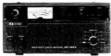
This is an all solid-state 500 W linear amplifier. The power amplifier unit can be separately set-up from the power supply unit.
AH-3 HF AUTOMATIC ANTENNA TUNER
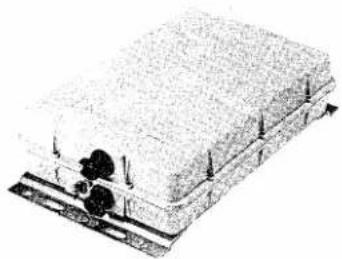
natural_image
Diagram of a layered structure with a central object and vertical supports (no text or symbols)Specially designed to tune a long wire antenna for portable or mobile operation. The IC-736/738 includes the control circuit for the AH-3.
• Input power rating : 150 W
IC-AT500 HF AUTOMATIC
ANTENNA TUNER

500 W automatic antenna tuner. Best match for the IC-736/738 with the IC-2KL.
Includes an automatic antenna selector for 4 separate antennas.
AT-150 HF AUTOMATIC ANTENNA TUNER
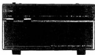
natural_image
Black rectangular electronic device with no visible text or symbols on its body, labeled 'L-DM' at top (no readable text beyond label)Includes an automatic antenna selector for 3 separate antennas, moreover, a long wire antenna can be tuned.
AH-2b ANTENNA ELEMENT

A 2.5 m long antenna element for mobile operation with the AH-3.
• Frequency coverage:
3.5 - 28 MHz band with the AH-3
EX-627 AUTOMATIC ANTENNA
SELECTOR
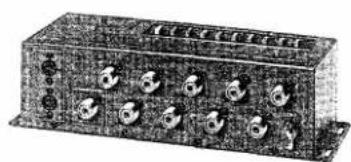
natural_image
Exterior view of a rectangular electronic device with multiple ports and connectors (no visible text or labels)Automatically selects the antenna for the selected ham band. Manual selection is also possible.
• Max. input power : 1000 W PEP
MB-49 MOBILE MOUNTING BRACKET
natural_image
Black metal tray with three compartments, no visible text or symbolsFirmly supports the transceiver for mobile operation.
12 OPTIONS
IC-PS15 DC POWER SUPPLY (IC-738 only)
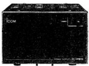
Heavy-duty power transformer system power supply. Style and size are matched with the IC-738.
• Output voltage : 13.8 V DC
• Max. current drain: 20 A
IC-PS30 DC POWER SUPPLY (IC-738 only)
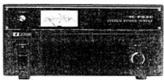
A lightweight switching regulator system power supply equipped with 2 DC power cables and 3 extra output connectors.
• Output voltage : 13.8 V DC
• Max. current drain: 25 A
PS-55 DC POWER SUPPLY (IC-738 only)

natural_image
Black and white photo of a rectangular electronic device with two legs and a textured top surface (no visible text or symbols)A heavy-duty power transformer system power supply. Built-in cooling fan for full-duty operation.
• Output voltage : 13.8 V DC
• Max. current drain: 20 A
SP-21 EXTERNAL SPEAKER

natural_image
Black rectangular electronic device with no visible text or symbols on its bodyDesigned for base station operation. Style and size are matched with the IC-736/738.
- Input impedance : 8 Ω
• Max. input power : 5 W
SP-20 EXTERNAL SPEAKER
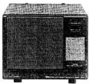
Equipped with 4 types of audio filters, a headphone jack and can be connected to 2 transceivers.
- Input impedance : 8 Ω
• Max. input power : 5 W
IC-SP3 EXTERNAL SPEAKER

natural_image
Black-and-white photo of a vintage electronic device with a circular vent and label (no readable text or symbols)External speaker designed for base station operation.
- Input impedance : 8 Ω
• Max. input power : 4 W
SP-7 EXTERNAL SPEAKER

natural_image
Black-and-white sketch of a rectangular box with a circular hole and a wireframe base (no text or symbols)Compact speaker for base station operation. Height can be adjusted for your convenience.
- Input impedance : 8 Ω
• Max. input power : 5 W
SM-20 DESKTOP MICROPHONE

natural_image
Illustration of a vintage desktop microphone with stand and cord (no text or symbols)Unidirectional, electret microphone for base station operation.
Includes [UP]/[DOWN] switches and a low cut function.
SM-8 DESKTOP MICROPHONE

natural_image
Illustration of a handheld electronic device with cables and a light bulb above it (no text or symbols visible)Electret condenser-type desktop microphone including 2 connection cables for simultaneous connection of 2 transceivers. [UP]/[DOWN] switches also come with the microphone.
SM-6 DESKTOP MICROPHONE

natural_image
Black office desk lamp with adjustable arm and cord (no visible text or symbols)Electret condenser-type desktop microphone for base station operation.
CT-16 SATELLITE INTERFACE UNIT

natural_image
Black electronic device with multiple wires and connectors, no visible text or symbolsEasy tuning when connecting another Icom VHF transceiver for instant satellite communications.
CT-17 CI-V LEVEL CONVERTER
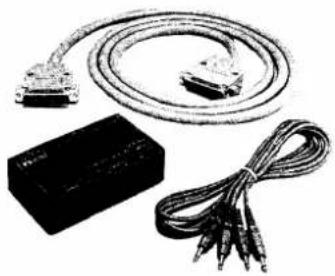
natural_image
Electrical cable and plug assembly with a black box and coiled wires (no text or symbols visible)For remote transceiver control using a personal computer equipped with an RS-232C port. You can change frequencies, operating mode, memory channels, etc., via your computer keyboard.
CR-282 HIGH-STABILITY CRYSTAL UNIT
natural_image
Close-up of an electronic component with no visible text or symbols on its bodyContains a temperature-compensating oven heater and crystal unit for improved frequency stability.
• Frequency stability: 0.5 ppm
(-30^ to +60^; -22^ to +140^)
FL-100 and FL-101
9 MHz CW NARROW FILTERS

natural_image
Illustration of an electronic component with a label and mounting feet (no readable text or symbols)Have good shape factor and provide you with better CW reception during crowded band conditions.
- FL-100:500 Hz/ -6 dB
- FL-101:250 Hz/-6 dB
FL-52A and FL-53A
455 kHz CW NARROW FILTERS
natural_image
Exterior view of a rectangular electronic component with a display screen (no visible text or symbols)Have good shape factor and provide you with better CW reception during crowded band conditions.
- FL-52A: 500 Hz/ -6 dB
• FL-53A : 250 Hz/−6 dB
UT-30 PROGRAMMABLE TONE
ENCODER UNIT

natural_image
Pure electrical circuit lines without any symbolsAllows you to access a repeater that requires a subaudible tone. Provides 38 programmable subaudible tones.
HM-36 HAND MICROPHONE

natural_image
Black-and-white photo of a handheld industrial control device with coiled tubing and a metallic connector (no visible text or symbols)The same as supplied with the transceiver.
Same type as supplied with the IC-738.
OPC-025A DC POWER CABLE (IC-738 only)
Count on us!

natural_image
Completely black image with no visible content or text.
- IMPORTANT
- PRECAUTIONS for the IC-736
- UNPACKING of the IC-736
- Accessories included with the IC-736: Qty.
- EXPLICIT DEFINITIONS
- PRECAUTIONS for the IC-738
- UNPACKING of the IC-738
- Accessories included with the IC-738: Qty.
- TABLE OF CONTENTS
- Technical information
- INDEX
- A
- B
- C
- D
- E
- F
- G
- H
- K
- L
- M
- N
- 0
- P
- Q
- R
- S
- T
- U
- V
- X
- FRONT PANEL INDEX
- PANEL DESCRIPTION
- Front panel
- FUNCTION
- SETTING PROCEDURE
- RIT SWITCH [RIT] (p. 28)
- RIT/ΔTX CONTROL [RIT/ΔTX] (p. 28)
- TX SWITCH [ TX ] (p. 28)
- NOTCH CONTROL [NOTCH] (p. 31)
- NOTCH SWITCH [NOTCH] (p. 31)
- PASSBAND TUNING CONTROL [PBT] (p. 31)
- MEMORY CHANNEL SELECTOR [M-CH] (p. 39)
- SCAN SWITCH [SCAN] (p. 46)
- CLEAR SWITCH [CLEAR] (p. 41)
- SELECT SWITCH [SEL] (p. 46)
- MEMORY WRITE SWITCH [MW]
- VFO/MEMORY SWITCH [VFO/MEMO] (p. 19)
- ⑤0 MEMORY TRANSFER SWITCH [M▶VFO]
- ■ Rear panel
- ■ Function display
- Microphone (HM-36)
- UP/DOWN SWITCHES [UP]/[DN]
- PTT SWITCH (p. 18)
- • MICROPHONE CONNECTOR
- • HM-36 SCHEMATIC DIAGRAM
- INSTALLATION AND CONNECTIONS
- Unpacking
- Selecting a location
- Grounding
- Antenna
- PL-259 CONNECTOR INSTALLATION
- ANTENNA SWR
- ■ Connections diagram
- ■ DC power supply connections (for the IC-738)
- Linear amplifier connections
- ■ AFSK terminal unit connections
- 3
- BASIC OPERATION
- When first applying power
- Initial settings
- - CW operation
- BASIC OPERATION
- VFO description
- VFO mode and memory mode
- Frequency setting with the main dial
- - For ham band use
- Direct frequency entry with the keypad
- [EXAMPLE]
- Advanced tuning functions
- QUICK TUNING STEP
- Programming the kHz step
- SELECTING THE 1 Hz STEP
- [UP]/[DOWN] SWITCH TUNING
- Programming the [UP]/[DOWN] switch tuning steps
- CHANGING THE NORMAL TUNING STEP
- AUTO TUNING STEP FUNCTION
- Receiving
- SSB RECEIVING
- Convenient functions for SSB receiving
- CW RECEIVING
- Convenient functions for CW receiving
- AM RECEIVING
- Convenient functions for AM receiving
- FM RECEIVING
- Convenient functions for FM receiving
- AFSK (RTTY, AMTOR, PACKET, etc.) RECEIVING
- Operating notes for RTTY and AMTOR receiving
- Operating notes for PACKET receiving
- Transmitting
- SSB TRANSMITTING
- Operating notes for SSB transmitting
- Convenient functions for SSB transmitting
- CW TRANSMITTING
- Operating notes for CW transmitting
- Convenient functions for CW transmitting
- AM TRANSMITTING
- Operating notes for AM transmitting
- Convenient functions for AM transmitting
- FM TRANSMITTING
- Operating notes for FM transmitting
- Convenient functions for FM transmitting
- AFSK TRANSMITTING
- Operating notes for AFSK transmitting
- Frequency setting example for AFSK transmitting
- FUNCTION OPERATIONS
- ■ Memo pad operation
- - Writing frequencies and operating modes into memo pads
- - Calling up a frequency from a memo pad
- RIT and △TX
- - RIT function
- PRACTICAL EXAMPLE
- - TX function
- • Calculate function
- Split frequency operation
- CONVENIENT
- DIAL LOCK FUNCTION
- Quick split function
- PROGRAMMING SPLIT SHIFT FREQUENCY
- PRE-OPERATION
- OPERATION
- VOX operation
- Meter function
- PBT operation
- Notch operation
- Set mode operation
- - Set mode operation
- Confirmation beep "bEEP"
- Auto tuning step function "tS-Aut"
- Filter selection "n-FIL"
- Scan resume "SC-rES"
- Scan speed "SC-SPd"
- Microphone up/down speed "UP-SPd"
- Memo pad capacity "PAd-CH"
- Antenna switch "Ant-SEL"
- Automatic tuner start "Aut-tun"
- Quick split function "q-SPLIT"
- Split lock cancel "SPLIT-L"
- Cl-V address "Cl-Addr"
- Cl-V baud rate "Cl-bAud"
- Cl-V transceive "Cl-trn"
- CI-V operating frequency data length "CI-731"
- ■ Band memory (for automatic antenna selection)
- [ANTENNA SWITCH SELECTION EXAMPLE]
- Remote jack (CI-V) information
- Antenna tuner operation
- TUNER OPERATION
- • For the HF band:
- • For the 50 MHz band (IC-736 only):
- MANUAL TURING
- Optional external tuner operation
- AH-3 HF AUTOMATIC ANTENNA TUNER
- ⚠ WARNING: HIGH VOLTAGE!
- AH-3 operation
- ANTENNA TUNER OF THE IC-4KL or IC-2KL/IC-AT500
- MEMORY CHANNELS
- ■ Memory channels
- ■ Memory channel selection
- Memory channel programming
- - Programming in the VFO mode
- • Programming in the memory mode
- Frequency transferring
- • Transferring in the VFO mode
- TRANSFERRING EXAMPLE IN THE VFO MODE
- • Transferring in the memory mode
- TRANSFERRING EXAMPLE IN THE MEMORY MODE
- Memory clearing
- Scan edge memory channels
- - Scan edge memory channel selection
- - Scan edge memory channel programming
- Split memory channels (for accessing a repeater)
- - Split memory channel selection
- - Split memory channel programming
- - Split memory channel operation
- - Split frequency transferring
- IN THE MEMORY MODE
- IN THE VFO MODE
- Scan types
- PROGRAMMED SCAN
- MEMORY SCAN
- SELECT MEMORY SCAN
- - Presetting
- - Scan resume ON/OFF
- - Squelch condition
- - Scan speed
- Programmed scan operation
- Memory scan operation
- Select memory scan operation
- MAINTENANCE AND ADJUSTMENT
- ■ Frequency calibration (approximate)
- Main dial brake adjustment
- ■ Fuse replacement (for the IC-736)
- ■ Fuse replacement (for the IC-738)
- CIRCUITRY FUSE REPLACEMENT
- ■ Opening the transceiver's case
- • To see the Main and PLL units
- • To see the Filter and Reg units (IC-736 only)
- LCD dimmer adjustment
- AC power voltage selection (for the IC-736)
- Tuner operating condition
- ■ PA idling current adjustment (for the IC-738)
- Lithium backup battery
- Cleaning
- 8
- OPTIONS INSTALLATION
- CW narrow filters
- FILTER SELECTION
- UT-30 PROGRAMMABLE TONE ENCODER UNIT
- CR-282 HIGH-STABILITY CRYSTAL UNIT
- MB-49 MOBILE MOUNTING BRACKET
- SPECIFICATIONS
- GENERAL
- TRANSMITTER
- RECEIVER
- ANTENNA TUNER
- OPTIONS
Mærke : ICOM
Model : IC-736
Kategori : Modtager