
D2050-VE - Detektor AXIS - Gratis brugsanvisning og manual
Find enhedens vejledning gratis D2050-VE AXIS i PDF-format.

Brugerspørgsmål om D2050-VE AXIS
0 spørgsmål om dette apparat. Besvar dem du kender, eller stil dit eget.
Stil et nyt spørgsmål om dette apparat
Download vejledningen til din Detektor i PDF-format gratis! Find din vejledning D2050-VE - AXIS og tag din elektroniske enhed tilbage i hånden. På denne side er alle dokumenter nødvendige for brugen af din enhed offentliggjort. D2050-VE af mærket AXIS.
BRUGSANVISNING D2050-VE AXIS
AXISD2050-VENetworkRadarDetector
TableofContents
Systemoverview....3
Productoverview......4
Wheretoinstalltheproduct....4
Mountingdirection....5
Mountingheight....5
Howtoaccesstheproduct....6
Howtoaccesstheproductfromabrowser......6
Aboutsecurepasswords......6
Setup......8
About the product's built-in help 8
Configurethedetector....8
Howtoconfigurethedetector....9
Howtoinstallmultipledetectors....9
Aboutevents....9
Howtorecordvideofromacamerawhenmotionisdetected.....1.0.
Howtorecordradardatawhenmotionisdetected....10.
Howtoturnonalightwhenmotionisdetected....1.1.
How to control PTZ camerawith the detector
Aboutelectionzones
Howtominimizefalsealarms....12.
Troubleshooting....14
Howtoresettofactorydefaultsettings....14.
Howtocheckthecurrentfirmware....14.
Howtoupgradethefirmware....14.
Technical issues and solutions
Performanceconsiderations....1.5.
Specifications....17
SDcardslot....17.
Buttons....17.
Connectors....17.
Operatingconditions....19.
Powerconsumption....19.
Systemoverview
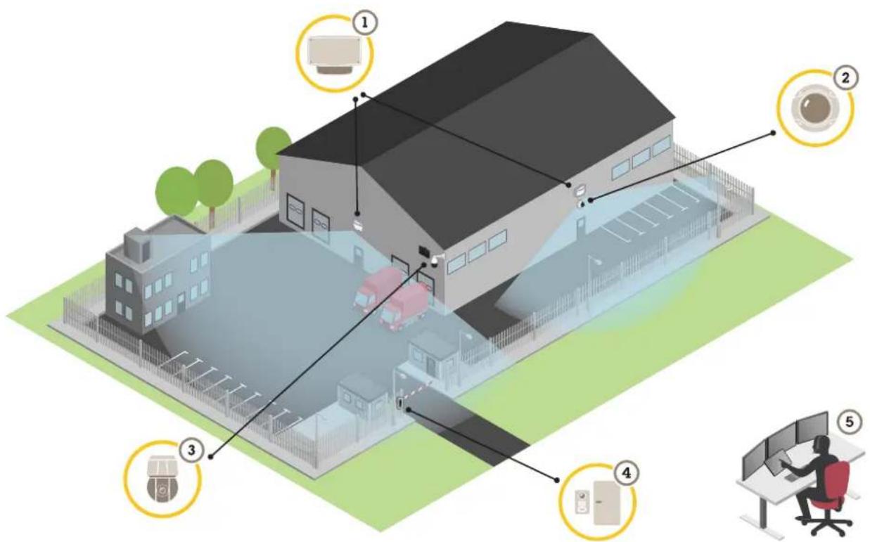
1 AXISD2050-VE
2 Fixeddomecamera
3 PTZcameraandilluminator
4 Doorcontroller
5 Surveillancecenter
Productoverview
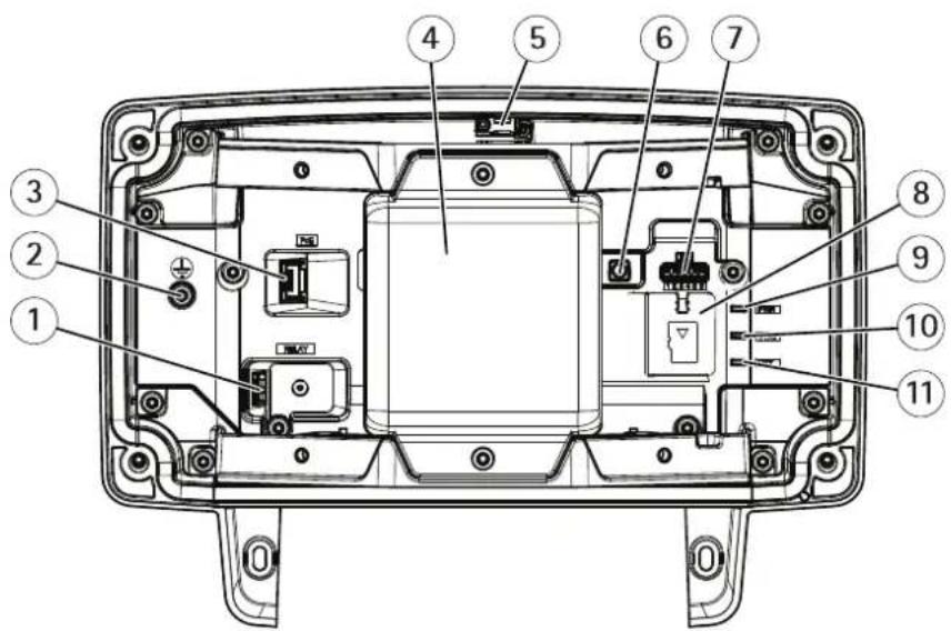
1 Relayconnector
2 Groundingscrew
3 Networkconnector
4 Radarmodule
5 Intrusionalarmswitch
6 Controlbutton
7 I/Oconnector
8 microSDcardslot
9 PowerLED
10 StatusLED
11 NetworkLED
Wheretoinstalltheproduct
The detector is intended for monitoring open areas. Anysolid object(such as at tree or a bush) in the coverage area will create a blind spot(radar shadow) behind it.
Installthedetectoronapole,oronaspotonawallwheretherearenootherobjectsoninstallationsclosetoit.
Tobeabletocorrectlyidentifymovementinthecoveragearea,thedetectorneedstobeinstalledonastablemount.Donot installthedetectoronaswayingpole.
If woradetectors are mounted close together, they may interfere with each other, how install multiple detectors on page9.
Attherecommendedmountingheight,theneardetectionlimitis4.5m(15ft).
If there are alotof metal objects in the field of view therewill bealotof reflections impacting the performance.
Note
Donotrepaintthedetector.Thepaintmayseriouslyimpactthedetector'sperformance.
Mountingdirection
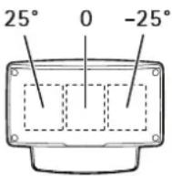
The detector covers an angle of ± 60^ from its central axis. This means that if you mount on a wall there is a blind spot to each side of the detector.
Tocoverthewallyoucanmovetheradarmoduleinsidethedetector.
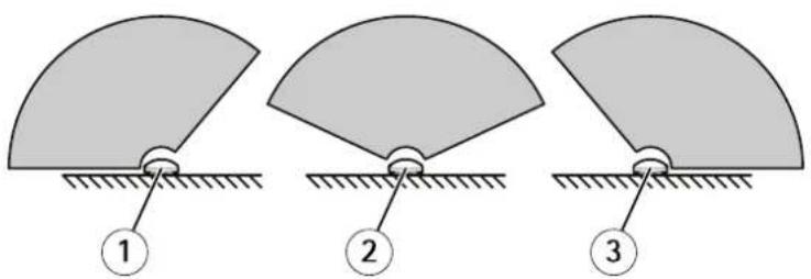
1 -25°mountingdirection
2 0°mountingdirection
3 25°mountingdirection
Mountingheight
Foroptimalperformance,installthedetector3.5m(11ft)aboveground.
Note
If you install the detector at different height, enter the actual mounting height in the product's web pages before calibrating the radar.
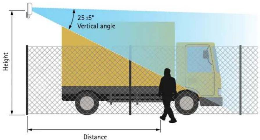
The following tables show sthedetection range at different mounting heights when detecting a 1.8m(6ft) tall person walking.
| Mountingheight | 3.5m(1 1ft)4m(13ft)4.5m(15ft)5m(16ft) | ||
| Neardetectionlimit | 4.5m(15ft)6m(20ft)7m(23ft)8.5m(28ft) | ||
| Fardetectionlimit(max.values)49m(161ft)51m(167ft)51m(167ft)52m(171ft) |
Howtoaccesstheproduct
AXISIPUtilityandAXISCameraManagementarecommendedmethodsforfindingAxisproductsonthenetworkandassigning themIPaddressesinWindows®.Bothapplicationsarefreeandcanbedownloadedfromaxis.com/support
Theproductcanbeusedwiththefollowingbrowsers:
- Chrome TM (recommended), Firefox ^ , Edge ^ , or Opera ^ with Windows ^
- Chrome ^TM (recommended)orSafari ^® withOSX ^®
- Chrome TM or Firefox® with other operating systems.
If you need more information about recommended browsers, goto axis.com/browser-support
Howtoaccesstheproductfromabrowser
1.Startawebbrowser.
2.EntertheIPaddressorhostnameoftheAxisproductinthebrowser'saddressfield.
ToaccesstheproductfromaMaccomputer(OSX),gotoSafari,clickonBonjourandselecttheproductfromthe drop-downlistcaddBonjourandbrowsebookmarkgotSafariPreferences.
If you donot know the Paddress, use AXISIP Utility to locate the product on thenetwork. For information about how to discover and assign Paddress through document Assign and Address and Access the Video Stream or Axis Support web a taxis.com/support
- Enteryourusernameandpassword.Ifthisisthefirsttimetheproductisaccessed,therootpasswordmustfirstbe configured.
- The product's live view page opens in your browser.
Aboutsecurepasswords
Important
Whensettingtheinitialpassword,thepasswordissentincleartextoverthenetwork.Ifthereisariskofnetworksniffing,firstsetupasecureandencryptedHTTPSconnectionbeforeresettingthepasswords.
The device password the primary protection forth data and services. Axis 'products donot impose permission policy as products maybe used in various types of installations, but to protect your data to the following:
- Don'tusethedefaultpasswordthatcomeswiththeproducts.
- Useapasswordwithatleast8characters,preferablyusingapasswordgenerator.
- Don'texposethepassword.
- Changepasswordatarecurringinterval, atleastonceayear.
Setapasswordfortherootaccount
Important
The default administrator us nam root can be deleted if the password for root is lost the product must be set to the factory default settings.
Thedefaultrootaccounthasfullprivilegesandshouldbereservedforadministrativetasks.Alwayscreateauseraccountwithlimited privilegesfordailyuse.Thisreducestheexposureoftheadministrativeaccount.
Make sure follow the instructions about secure passwords see About secure passwords page
- Typeapasswordandthenretypeittoconfirmthespelling.
3.ClickCreate login. The password has now been configured.
Setup
About the product's built-in help
Youcanaccessthebuilt-inhelpthroughyourproduct'swebpage.Thehelpprovidesmoredetailedinformationontheproduct's featuresandtheirsettings.
Configurethedetector
The detector is ready to use as soon as it is installed. The default live view will show that the radar coverage and any detected movement, and you can add detection zones and action rules right away.
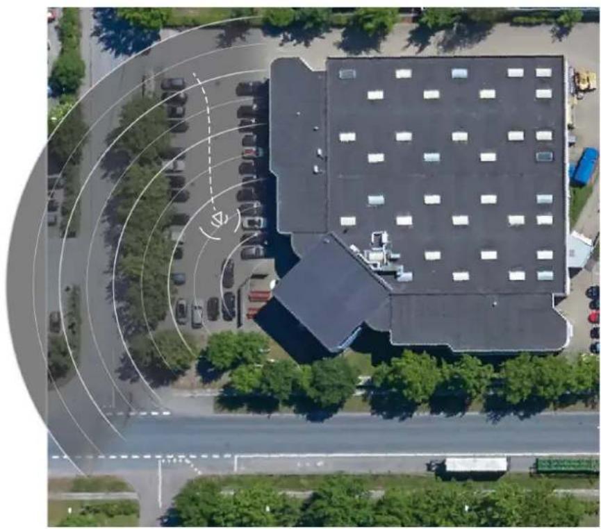
Tomakeiteasiertoseewhereobjectsaremoving,youcanuploadareferencemap,forexampleagroundplanoranaerialphoto,thatshowstheareacoveredbytheradardetector.
natural_image
Aerial view of a modern building with circular traffic markings, surrounded by parked cars and greenery (no visible text or symbols)Imagerequirements:
• Supportedfileformatsarejpegandpng.
- Useanimagewiththesameproportions(16:9)orresolution(1920x1080)asthelivewview.Iftheimageissmalleritwillbe scaledtofitthewindow.Iftheproportionsarewrong,theimagewillnotfilltheentirevideostream.
- Croptheimagetofitthecoverageoftheradarascloselyaspossiblebeforeuploadingit.
- Theorientationisnotimportant,sincetheradarcoverageshapewillbemovedtoadapttotheimageduringcalibration.
After uploading thereferencemap you needed to calibrate theradar so that the actual radar coverage fits the position, direction and scale of thereferencemap.
Therearetwomethodsforcalibratingthereferencemap:
Calibrationusing in the calibration performed the web interface by dropping in a known location in the reference map and setting the distance between the pins.
Whencalibratingusingpins,youneedtoselectthemountingpositionoftheradarmoduleinsidethedetector.
CalibrationusingtracksThecalibratiomethodequirespersortomoverfrontoftheadar.
Youcandothisyourselfwhileaccessingthewebinterfacefromamobiledevice,orhavesomeoneelsemoveand followyourinstructions.
Whenmovingaroundinthedifferentsteps, movetoplacesthatareeasytofindinthereferencemap.
Howtoconfigurethedetector
UploadreferencmapdSettingsRadarReferencmapSelectBrowsefindImagefileandselectUploadtoplacetheimageintheliveview.
Dealibrate the reference map to Settings Radar Reference calibration Select Start calibration and followthe instructions.
Howtoinstallmultipledetectors
Iftworadardetectorsofaremountedclosetogethertheymayinterferewitheachother.Toavoidproblems,selectdifferent channelsforthedetectors.
GoSettingsRadarGeneralandelecChannel.
Aboutevents
The event pages allow you to configure your product to perform actions when different events occur. For example, the product can start are recording or send an email notification when motion is detected. The set of conditions that defines show and when the action is triggered discalled an action rule.
Howtorecordvideofromacamerawhenmotionisdetected
This example explains how to set up the detector and acameraso that the camera starts recording to the SD card five seconds before the detector detects motion and to stop on minute after.
Connectthedevices:
- Connectacablefromanl/Ooutputonthedetectortoanl/Oinputonthecamera.
Configurethel/Oportofthedetector:
QdSettingsSystem/Oportandconfigure/the/Oportanoutputandselectenormastate.
Createanactionruleinthedetector:
- GotoSettings>System>Eventsandaddanactionrule.
4.Typeanamefortheactionrule.
EonthdisbfriggersselecDetectorsandhenselectnothRMD(RadaMotionDetection)includezonesToet upanincludezone,seeAddanincludezoneonpage12
6onthdisbictionsselectOutputPortandheselectheporthatsconnectedd camera.
SethDurationGdoppositstatwherthculindongeactive.
8.ClickOk.
Configurethel/Oportofthecamera:
GoSettingsSystem/Oportandconfigure/Qportarinputandselectnormastate.
Createanactionruleinthecamera:
10.GotoSettings>System>Eventsandaddanactionrule.
11.Typeanamefortheactionrule.
12 FrontheisbfriggersselecDigitalInputPortandherselecthorthathouldtriggetheule.
13.Fromthelistofactions,selectRecordvideo.
-
Selectanexistingstreamprofileorcreateanewone.
-
Setthepre-triggertimeto5seconds.
-
Setthepost-triggertimeto60seconds.
-
SelectSDcardfromthelistofstorageoptions.
18.ClickOk.
Howtorecordradardatawhenmotionisdetected
This example explains how to setup the detector to start recording to the SD card five seconds before it detects motion and to stop on minute after.
Therecordingwillshowthereferencemapwiththetrailofthemovingobject.
Createanactionrule:
- GotoSettings>System>Eventsandaddanactionrule.
2.Typeanamefortheactionrule.
BonthdisbfriggersselecDetectorsandheselectnothRMD(RadaMotionDetection)includezonesIset upanincludezone,seeAddanincludezoneonpage12
- From the list of actions, select Record video.
- Selectanexistingstreamprofileorcreateanewone.
6.Setthepre-triggertimeto5seconds. - Setthepost-triggertimeto60seconds.
- SelectSDcardfromthelistofstorageoptions.
9.ClickOk.
Howtoturnonalightwhenmotionisdetected
Turningonalightwhenanintruderentersthedetectionzonecanhaveadeterringeffect,andwillalsoimprovetheimagequalityof avisualcamerarecordingtheintrusion.
This example explains how to set up the detector and an illuminators that the illuminator turns on when the detector detects motion and turn soff after one minute.
Connectthedevices:
- Connectoneoftheilluminatorcablestothepowersupplyviatherelayportonthedetector. Connecttheothercable directlybetweenthepowersupplyandtheilluminator.
Configuretherelayportofthedetector:
QdSettingsSystem/PortandelecOperircuitshenormastate.
Createanactionruleinthedetector:
3.GotoSettings>System>Eventsandaddanactionrule.
4.Typeanamefortheactionrule.
FonthdisbfriggersselecDetectorsandhenselecbnofhRMD(RadaMotionDetection)includezonesToet upanincludezone,seeAddanincludezoneonpage12
- From the list of actions, select Output Port and then select the relay port.
7.SelectActive.
SethDurationGdoppositstateafterminute.
9.ClickOk.
HowtocontrolaPTZcamerawiththedetector
Itispossibletousetheinformationaboutobjects'positionsfromthedetectortomakeaPTZcameraatrackobjects.
Todothis, install the application AXISRadarAutotracking for PTZonyourVMSserver(oranothercomputerwithaccesstoboththe cameraandthedetector), and follow the instructions in the application.
TodownloadAXISRadarAutotrackingforPTZ, gotoaxis.com
Aboutdetectionzones
Todeterminewheretodetectmotion,youcanaddmultiplezones.Differentzonescanbeusedtotriggerdifferentactions.
Therearetwotypesofzones:
A include zones are an which moving objects with trigger action rules. The default includes zone matches the entire area recovered by the detector.
Are exclude zones are in which moving objects will be ignored. Use exclude zones either are areas inside include zonethattriggeralotofunwantedalarms.
Addanincludezone
- GotoSettings > RMDzonesandclick

2.SelectIncludezone.
3.Select

tomodifythesettingsofthezone.Formoreinformation,seetheproduct'sbuiltinhelp.
- Modify the shape of the includezone, see Modify detection zone on page 12
Addanexcludezone
- GotoSettings > RMDzonesandclick

2.SelectExcludezone.
- Modify the shape of the exclude zone, see Modify detection zone on page 12
Modifyadetectionzone
Usethemousetomoveandshapethezonesothatitcoversthedesiredpartofthereferencemap.
- Toaddanewcorner, clickonthezoneborder. Dragthecornertothedesiredposition.
- Toremoveacorner, right-clickonthecorner.
- Tomoveacorner, clickanddragthecornertothenewposition.
- Tomovethezone, placethepointerinsidethezone and drag the zoneto thenew position.
Howtominimizefalsealarms
If you notice that you get to many false alarms, you can filter out certain types of movement or objects, or can get the coverage. Test which setting works best for your environment.
- Modifytheincludeandexcludezones:
If the include zone includes hardsurfaces, such as a metal wall, ther may be reflection that causes multiple detections for single physical object this as modify the include zones. Modify detection zone on page 12 add are exclude zonethat mask everything behind the surface, see Addanexclude zone on page 12
- Filteronmovement:
GdsSettingsRadarDetectionandelectignorewayingobjectsThisettingvilminimizefalsalarmsfrontrees, bushes,andflagpolesinthecoveragezone.
-Filterontime:
GotoSettings>RMDzonesandselectazonetomodifyit'ssettings.
Enable Short-lived object and delay time from whether ahead starts tracking object until cartridge alarm. The timer starts when the radar first detects the object, not when the object enter the include zone.
Setup
-Filteronobjecttype:
The detector will classify objects depending on the data that they produce. If can't determine the object type, the object will be classified as Unidentified.
GotoSettings>RMDzonesandselectazonetomodifyit'ssettings.
To avoid triggering specific object types, enable the filter and deselect the object type that should not triggerevents in this zone.
Troubleshooting
Howtoresettofactorydefaultsettings
Important
Resettofactorydefaultshouldbeusedwithcaution.Aresettofactorydefaultresetsallsettings,includingtheIPaddress,to thefactorydefaultvalues.
Toresettheproducttothefactorydefaultsettings:
- Disconnectpowerfromtheproduct.
Presandhold the controbuttonwhile reconnectingpowerSeeProductoverview. - Keep the control button pressed for 15–30 seconds until the status LED indicator flashes amber.
- Releasethecontrolbutton. The process is complete when the status LED indicator turns green. The product has been reset that factory default settings and DHC serve available on the network the default address 92.168.0.90
- UsetheinstallationandmanagementsoftwaretoolstoassignanlPaddress, setthepassword, andaccessthevideostream.
The installation and management software tools are available from the support pages on axis.com/support
It's also possible to reseparameters factor default via the web interfaceGoSettingsSystemMaintenance and clickDefault.
Howtocheckthecurrentfirmware
Firmwareisthesoftwarethatdeterminesthefunctionalityofnetworkdevices.Oneofyourfirstactionswhentroubleshootinga problemshouldbetocheckthecurrentfirmwareversion.Thelatestversionmaycontainacorrectionthatfixesyourparticular problem.
Tocheckthecurrentfirmware:
-
Gototheproduct'swebpage.
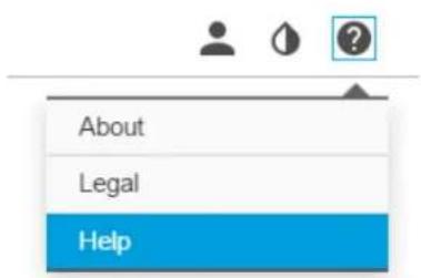
-
Clickonthehelpmenu.
3.ClickAbout.

Howtoupgradethefirmware
Important
Preconfiguredandcustomizedsettingsaresavedwhenthefirmwareisupgraded(providedthatthefeaturesareavailableinthenewfirmware)althoughthisisnotguaranteedbyAxisCommunicationsAB.
Important
Makesuretheproductremainsconnectedtothepowersourcethroughouttheupgradeprocess.
Note
When you upgrade the product with the latest firmware, the product receives the latest functionality available. Always read the upgrade instructions and release notes available with each new release before upgrading the firmware. To find the latest firmware and therele asenotes, goto axis.com/support/firmware
-
Download the latest firmware file to your computer, available free of charge at axis.com/support/firmware
-
Logintotheproductasanadministrator.
GoSettingsSystemMaintenanceProduct'swebpageandfollowinstructions?Whertheupgradehas finished,theproductrestartsautomatically.
Technicalissues,cluesandsolutions
If you can't find what you're looking for here, try the troubleshooting section at axis.com/support
Problemsupgradingthefirmware
| Firmwareupgradefailurelfthefirmwareupgradefails,theproductreloadsthepreviousfirmware.Themostcommonreasonisthatthewrongfirmwarefilehasbeenuploaded.Checkthatthenameofthefirmwarefilecorrespondstoyourproductandtryagain. | |
| ProblemssettingthelPaddress | |
| Theproductislocatedona differentsubnet | IfthelPaddressintendedfortheproductandthelPaddressofthecomputerusedtoaccessthe productarelocatedondifferentsubnets,youcannotsetthelPaddress.Contactyournetwork administratorortoobtainanlPaddress. |
| ThelPaddressisbeingused byanotherdevice | DisconnecttheAxisproductfromthenetwork.Runthepingcommand(inaCommand/DOS window,typepingandthelPaddressoftheproduct):·Ifyoureceive:Replyfrom:bytes=32;time=10... thismeansthatthelPaddressmayalreadybeinusebyanotherdeviceonthenetwork. ObtainanewlPaddressfromthenetworkadministratorandreinstalltheproduct.·Ifyoureceive:Requesttimedout,thismeansthatthelPaddressisavailable forusewiththeAxisproduct.Checkallcablingandreinstalltheproduct. |
| PossiblelPaddressconflict withanotherdeviceonthe samesubnet | ThestaticlPaddressintheAxisproductisusedbeforetheDHCPserversetsadynamicaddress. ThismeansthatifthesamedefaultstaticlPaddressisalsousedbyanotherdevice,theremay beproblemsaccessingtheproduct. |
| Theproductcannotbeaccessedfromabrowser | |
| Cannotlogin | WhenHTTPSisenabled,ensurethatthecorrectprotocol(HTTPorHTTPS)isusedwhenattempting tdognYoumayneedmanuallytypehttporthttpsinthebrowser'saddressfield.Ifthepasswordfortheuserrootislost,theproductmustberesettothefactorydefaultsettings.SeeHowtorettofactorydefaultsettings. |
| ThelPaddresshasbeen changedbyDHCP | |
| Theproductisaccessiblelocallybutnotexternally | |
| Routerconfiguration | CheckthatyourrouterallowsincomingdatatraffictotheAxisproduct.Theroutermustsupport UPnP®. |
| Firewallprotection | ChecktheInternetfirewallwithyournetworkadministrator. |
Performanceconsiderations
Whensettingupyour system, it is important to consider how various settings and situations affect the performance. Some factors affect the amount of bandwidth (the bitrate) required, others can affect the framerate, and some affect both. If the load on the CPU reaches its maximum, this also affects the framerate.
The following factors are them most important to consider:
Troubleshooting
- Highimageresolutionorlowercompressionlevelsresultinimagescontainingmoredatawhichinturnaffectsthe bandwidth.
- AccessbylargenumbersofMotionJPEGorunicastH.264clientsaffectsthebandwidth.
- Simultaneousviewingofdifferentstreams(resolution, compression)bydifferentclientsaffectsbothframerateand bandwidth.
Use identical streams wherever possible to maintain a high framerate. Stream profile can be used to ensure that streams are identical.
- AccessingMotionJPEGandH.264videostreamssimultaneouslyaffectsbothframerateandbandwidth.
- Heavyusageofeventsettingsaffectstheproduct'sCPUloadwhichinturnaffectstheframerate.
- UsingHTTPSmayreduceframerate, inparticularifstreamingMotionJPEG.
- Heavynetworkutilizationduetopoorinfrastructureaffectsthebandwidth.
- Viewingonpoorlyperformingclientcomputerslowersperceivedperformanceandaffectsframerate.
- RunningmultipleAXISCameraApplicationPlatform(ACAP)applicationssimultaneouslymayaffecttheframerateand thegeneralperformance.
Specifications
Tfindtheatestversionofthproduct'slatasheetgddtheproducpagomaxis.comandocatSupportDocumentation.
LEDIndicators
| StatusLED | Indication |
| GreenSteadygreenfornormaloperation. | |
| Amber | Steadyduringstartup.Flasheswhenrestoringsettings. |
| NetworkLEDIndication | |
| Green | Steadyforconnectiontoa100Mbit/snetwork.Flashesfornetworkactivity. |
| Amber | Steadyforconnectiontoa10Mbit/snetwork.Flashesfornetworkactivity. |
| UnlitNonetworkconnection. |
| PowerLEDIndication | |
| Green | Normaloperation. |
| Amber | Flashesgreen/amberduringfirmwareupgrade. |
SDcardslot
ForSDcardrecommendations,seeaxis.com
Buttons
Controlbutton
Forlocationofthecontrolbutton,seeProductoverviewonpage4.
Thecontrolbuttonisusedfor:
- Resetting the product to factory default settings. See page 14.
- ConnectingtoanAXISVideoHostingSystemservice.See.Toconnect,pressandholdthebuttonforabout3seconds untiltheStatusLEDflashesgreen.
Connectors
Networkconnector
RJ4EthernetconnectorwithPowepveEthernePlus(PoE+).
I/Oconnector
Used/Oconnectowithexternadevicescombinationwithforexamplemotiondetectioneventriggeringandalarm notifications.InadditiontotheOVDReferencepointandpower(DCoutput),thel/Oconnectorprovidestheinterfaceto:
DigitalInputForconnecting devices that to toggle between an open and closed circuit for example PL Sensors door/window contacts, and glass break detectors.
DigitabutputForconnectingexternaldevicesuchaselayandLEDsConnecteddevicesarbactivatedbythe/APIX® ApplicationProgrammingInterfaceorintheproduct'swebpage.
6-pinterminalblock
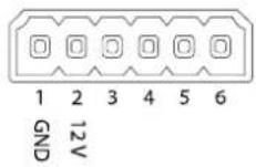
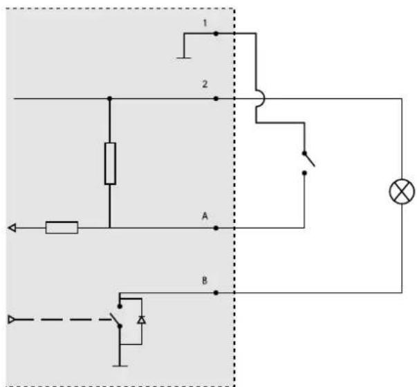
1 OVDC(-)
2 DCoutput12V,max50mA
A I/Oconfiguredasinput
B I/Oconfiguredasoutput
Relayconnector
△CAUTION
Usesinglecorewiresfortherelayconnector.
| Function | Specifications |
| TypeNormallyopen | |
| Rating | 24VDC |
| Max.current5A | |
| Isolationfromothercircuitry2.5kV | |
| Electricalendurance | 24VDC,25000operationsat+70°C(158°F) |
Operatingconditions
| Product | Classification | TemperatureHumidity | |
| AXISD2050-VEIEC60529IP66NEMA250Type4X | -40^ Cto 60^ C( -40^ Fto 140^ F) | 10–100%RH(condensing) | |
Powerconsumption
NOTICE
UseaSafetyExtraLowVoltage(SELV)compliantlimitedpowersource(LPS)witheitheraratedoutputpowerlimited to≤100Varatedoutputcurrentlimited≤5A.
| ProductPoweroverEthernetPower | |
| AXISD2050-VEIEEE802.3at,Type2Class4 | Typical9WMax.15W |
- TableofContents
- Productoverview
- Wheretoinstalltheproduct
- Mountingdirection
- Mountingheight
- Howtoaccesstheproduct
- Howtoaccesstheproductfromabrowser
- Aboutsecurepasswords
- Important
- Setapasswordfortherootaccount
- Setup
- About the product's built-in help
- Configurethedetector
- Imagerequirements:
- Howtoconfigurethedetector
- Howtoinstallmultipledetectors
- Aboutevents
- Howtorecordvideofromacamerawhenmotionisdetected
- Howtorecordradardatawhenmotionisdetected
- Howtoturnonalightwhenmotionisdetected
- HowtocontrolaPTZcamerawiththedetector
- Aboutdetectionzones
- Addanincludezone
- Addanexcludezone
- Modifyadetectionzone
- Howtominimizefalsealarms
- Troubleshooting
- Howtoresettofactorydefaultsettings
- Howtocheckthecurrentfirmware
- Howtoupgradethefirmware
- Note
- Technicalissues,cluesandsolutions
- Performanceconsiderations
- Specifications
- SDcardslot
- Buttons
- Controlbutton
- Connectors
- Networkconnector
- I/Oconnector
- Relayconnector
- △CAUTION
- Powerconsumption
- NOTICE
Mærke : AXIS
Model : D2050-VE
Kategori : Detektor