MXT-1001 - Skærm AMX - Gratis brugsanvisning og manual
Find enhedens vejledning gratis MXT-1001 AMX i PDF-format.

Brugerspørgsmål om MXT-1001 AMX
0 spørgsmål om dette apparat. Besvar dem du kender, eller stil dit eget.
Stil et nyt spørgsmål om dette apparat
Download vejledningen til din Skærm i PDF-format gratis! Find din vejledning MXT-1001 - AMX og tag din elektroniske enhed tilbage i hånden. På denne side er alle dokumenter nødvendige for brugen af din enhed offentliggjort. MXT-1001 af mærket AMX.
BRUGSANVISNING MXT-1001 AMX
Overview
In the MXT-1001 10.1" Modero X Series® G5 Tabletop Touch Panel (FG5968-47), the most elegant interface designed specifically for dedicated room control has been significantly enhanced to include a new G5 Graphic Engine to provide even faster and smoother animations and transitions. It also quadruples the processing power with a new Quad Core Processor. This new generation of touch panels is built for usability offering edge-to-edge capacitive touch glass with multi-touch capabilities. It features advanced technology empowering users to operate AV equipment seamlessly, while providing the ultimate in audio and video quality. The distinctive appearance will complement even the most sophisticated meeting facilities and homes. With a lightning fast processor, brilliant graphics and enhanced capabilities, the Modero X Series is the control surface that simply delivers more.
For more information on installation and configuration, please refer to the MXT/MXD-1001 Operation Reference Guide, available at www.amx.com.
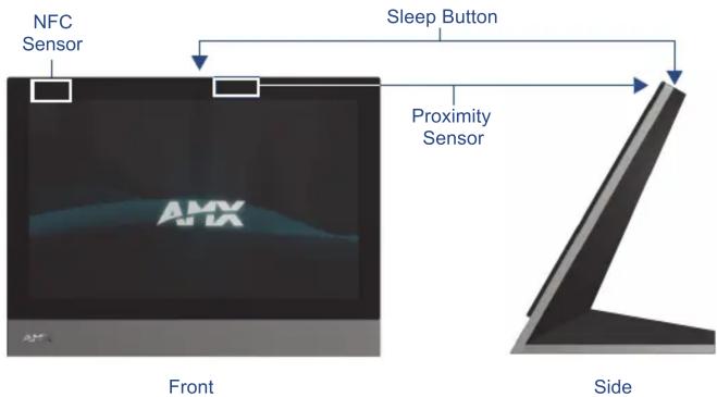
FIG. 1 MXT-1001
Common Application
The MXT-1001 is intended for boardrooms, conference rooms, or auditoriums where a panoramic control surface is needed to provide access to multiple functions simultaneously while remaining elegantly unobtrusive. In residences, it is perfect for kitchens, home theaters, or home offices where the panoramic control surface can be used to manage systems throughout the house.
Features
- G5 Graphics Engine and Quad Core Processing – The most powerful processing in the industry delivers smooth gesturing, animations and transitions all at higher speeds for an experience any user will enjoy.
- Apps - Modero X Series G5 touch panels now have the ability to run stand-alone applications (apps) within the control environment.
- Simplified Enterprise Touch Panel Updates – Deploy and update touch panel files from a network URL for simplified company-wide updates.
- Latest Communication Technologies – Supports Near Field Communication™ (NFC) - short-range wireless technologies that deliver peer-to-peer communication by 'sharing, pairing and transaction' between RF devices like exchanging data/identities.
- Enhanced Usability – HD video streaming.
- Perfect From Any Angle – Includes In-Plane Switching (IPS), the latest technology in popular tablet/mobile devices that delivers the widest viewing angles and the most accurate color reproduction on the market.
Product Specifications
| MXT-1001 (FG5968-03) Specifications | |
| Power: PoE (Power over Ethernet), 802.3af, class 3 | |
| Power Consumption: • Full | On: 12.95 W maximumStandby: 5.8 WShutdown: 1 W |
| Operating Environment: • Operating Temperature: 32° F to 104° F (0° C to 40° C)Storage Temperature: 4° F to 140° F (-20° C to 60° C)Humidity Operating: 20% to 85% RHHumidity Storage: 5% to 85% RH | |
| Dimensions (HWD): | 6 14/16" x 9 14/16" x 4 14/16" (174 mm x 252 mm x 124 mm) |
| Weight: | 3.0 lbs (1.36 kg) |
| MXT-1001 (FG5968-03) Specifications | |
| Certifications: • UL | • FCC Part 15 Class B• C-Tick CISPR 22 Class B• CE EN 55022 Class B and EN 55024• CB Scheme IEC 60950-1• IC• IEC/EN-60950• R o H S |
| Included Accessories: | • MXT-1001 Installation Guide (93-5968-47)• MXA-CLK Modero X Series Cleaning Kit (FG5968-16)• HPG-10 .75-inch HydraPort .75-IN. Grommet (FG570-01) |
| Other AMX Equipment: • PS-POE-AF-TC, POE Injector, 802.3af Compliant (FG423-83)• MXA-USB-C USB Cover Kit (FG5968-18)• NXA-ENET8-2POE, Gigabit Switch, 8 Port POE, 2 Port SFP (FG2178-63)• MXA-MPL, Modero X Series Multi Preview Live (FG5968-10)• MXA-MP, Modero X Series Multi Preview (FG5968-20)• MXA-STMK-10, Secure Table Mount Kit, 10.1" Modero X Tabletop (FG5968-66) | |
Panel Connectors and Wiring
Any USB peripherals (mouse, keyboard, etc.) may be connected to one of the two USB ports on the rear of the device (FIG. 2). Updates to the device's firmware are also made via the USB ports. The 5-pin Micro-USB port is used exclusively for camera video and microphone output only.
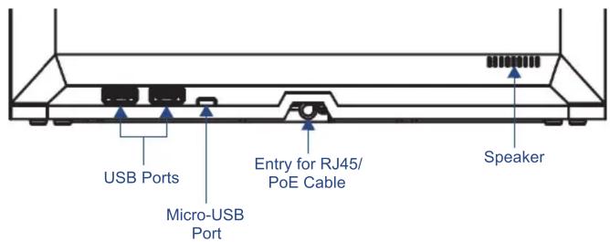
FIG. 2 Connectors on the rear of the MXT-1001
Power via Power Over Ethernet
Power for the MXT-1001 is supplied via Power Over Ethernet (PoE), utilizing an AMX-certified, capacitive touch-compliant PoE injector such as the PS-POE-AT High Power PoE Injector (FG423-81) or equivalent PoE device. If using a PoE injector, the PoE injector should be installed between the MXT-1001 and the incoming Ethernet cable, and connected to the RJ45 port on the cable attached to the device (FIG. 3).
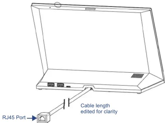
FIG. 3 Back of the MXT-1001, showing RJ45 port and cable for PoE
Ethernet Cable Installation and Modification
In installations where you wish to conceal the Ethernet cable, a hole at least 1.00" (2.54 cm) in diameter is required in the surface to allow passage of the female RJ45 connector (FIG. 3). If using a smaller hole is unavoidable, you will need to disconnect the Ethernet cable (ECA5968-05) from the device.
NOTE: The minimum diameter hole through which the Ethernet cable may pass is 0.50" (1.27 cm).
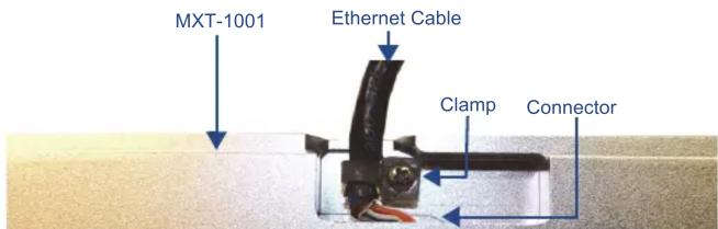
FIG. 4 Bottom of the MXT-700
To disconnect and reconnect the MXT-1001's Ethernet cable to allow use of a hole smaller than 1.00" in diameter:
- On a soft surface, turn the MXT-1001 face-down to access the bottom of the device.
- Remove the clamp holding the Ethernet cable (FIG. 4) until the Ethernet cable moves freely.
- Remove the Ethernet cable connector and pull the cable out of the clamp.
- Pass the Ethernet cable (ECA5968-05) through the hole, with the RJ45 connector on the other side of the installation surface from the device.
- Press the Ethernet cable back into the clamp. Do NOT tighten the clamp at this time.
- Using a nonconductive item such as a wooden stick, reinsert the Ethernet cable connector into the device. Use the stick to ensure that the connector is properly seated.
- Tighten the clamp to secure the Ethernet cable. Make sure the clamp is around the bundled black cable, not the individual wires.
- Connect the RJ45 connector to its incoming Ethernet cable and apply power.
Configuring the MXT-1001
The MXT-1001 is equipped with a Settings app that allows you to set and configure various features on the panel. For more information on connecting and configuring the MXT-1001 to a network, please refer to the Modero X Series G5 Programming Guide, available at www.amx.com.
Accessing the Settings App
To access the Settings app on the MXT-1001, press and hold the Sleep Button (FIG. 1) on the top of the panel for 3 seconds. The user will be prompted to release the button to enter the Settings app.
Accessing the NetLinx Subpage
- From the Settings app page, select NetLinx. This opens a password keypad.
- Enter the panel password into the keypad (the default is 1988) and select OK to access the subpage.
Setting the Panel's Device Number and Device Name
In the NetLinx subpage:
- Press Device Number to open the NetLinx editing window.
- Enter a unique Device Number assignment for the panel and press OK.
- Enter a unique Device Name assignment for the panel and press OK.
Accessing the Ethernet Subpage
- From the Settings app, select Ethernet. This opens a password keypad.
- Enter the panel password into the keypad (the default is 1988) and select OK to access the subpage.
Connecting to a Master
The panel requires that you establish the type of connection you want to make between it and your Master.
In the NetLinx page:
- Press Mode to toggle through the available connection modes:
| Connection Modes | ||
| Mode | Description Procedures | |
| Auto The device connects to the first master that responds.This setting requires that you set the System Number. | Setting the System Number:1. Select Master System Number to open the keypad.2. Set your Master System Number and select OK. | |
| URL The device connects to the specific IP of a master via a TCP connection.This setting requires that you set the Master's IP. | Setting the Master IP:1. Select the Master IP number to open the keyboard.2. Set your Master IP and select OK. | |
| Listen The device "listens" for the Master to initiate contact.This setting requires you provide the master with the device's IP. | Confirm device IP is on the Master URL list. You can set the Host Name on the device and use it to locate the device on the master. Host Name is particularly useful in the DHCP scenario where the IP address can change. | |
- If you have enabled password security on your Master, you need to set the username and password within the device.
a. Select Username to open the NetLinx editing window.
b. Set your Username and Master Password.
e. Click OK to return to the NetLinx page.
Configuring the Panel to a Network
The first step is to configure the panel's communication parameters. This only configures the panel to communicate with a network, and it is still necessary to tell the panel with which Master it should be communicating.
Network Communication With a DHCP Address
In the Ethernet subpage:
- Toggle the DHCP/Static field to open the DHCP/Static window. DHCP is the default setting. This action causes all fields on the Ethernet subpage (other than Host Name) to be greyed-out.
- Select Host Name to open the Host Name window. Enter the new host name and click OK.
Network Communication with a Static Address
In the Ethernet subpage:
- Toggle the DHCP/Static field to open the DHCP/Static window.
- Select Static in the window. This opens the Static IP editing window.
- Click on any field to open either a keypad (for numeric entries) or keyboard (for alphanumeric entries). To minimize the keypad/keyboard, click the two downward-pointing arrows at the bottom right corner of the screen.
- Enter your network's information in the Static IP editing window. To move from field to field, simply press the next field you wish to edit.
- When finished, click OK to save your changes and return to the Ethernet subpage.