MXT-1901-PAN - Skærm AMX - Gratis brugsanvisning og manual
Find enhedens vejledning gratis MXT-1901-PAN AMX i PDF-format.

Brugerspørgsmål om MXT-1901-PAN AMX
0 spørgsmål om dette apparat. Besvar dem du kender, eller stil dit eget.
Stil et nyt spørgsmål om dette apparat
Download vejledningen til din Skærm i PDF-format gratis! Find din vejledning MXT-1901-PAN - AMX og tag din elektroniske enhed tilbage i hånden. På denne side er alle dokumenter nødvendige for brugen af din enhed offentliggjort. MXT-1901-PAN af mærket AMX.
BRUGSANVISNING MXT-1901-PAN AMX
Overview
In the MXT-1901-PAN 19.4" Modero X Series G5 Panoramic Tabletop Touch Panel (FGS968-41), the most elegant interface designed specifically for dedicated room control has been significantly enhanced to include a new G5 Graphic Engine to provide even faster and smoother animations and transitions. It also quadruples the processing power with a new Quad Core Processor. This new generation of touch panels is built for usability offering edge-to-edge capacitive touch glass with multi-touch capabilities. It features advanced technology empowering users to operate AV equipment seamlessly, while providing the ultimate in audio and video quality. The distinctive appearance will complement even the most sophisticated meeting facilities and homes. With a lightning fast processor, brilliant graphics and enhanced capabilities, the Modero X Series is the control surface that simply delivers more.
For more information on installation and configuration, please refer to the MXT/MXD-1901-PAN Operation Reference Guide, available at www.amx.com
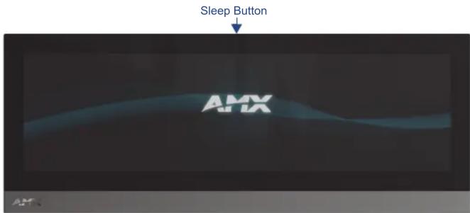
FIG. 1 MXT-1901-PAN 19.4" Panoramic Tabletop Touch Panel
Common Application
The MXT-1901-PAN is ideal for boardrooms, conference rooms, or auditoriums where a panoramic control surface is needed to provide access to multiple functions simultaneously while remaining elegantly unobtrusive. In residences, it is perfect for kitchens, home theaters, or home offices where the panoramic control surface can be used to manage systems throughout the house.
Features
- Panoramic Control Surface – Combined with the new PanTastic UI, the panoramic touch panels take the user experience to a whole new level with an impressive control surface to perform activities much in the same way you use a computer – multi-tasking with dedicated spaces.
- Apps - Modero X Series G5 touch panels now have the ability to run stand-alone applications (apps) within the control environment.
- Future Technology Visions – HD video chat and conferencing using integrated camera and hardware - ready to support Near Field Communication (NFC) Technology, which promises short-range wireless technologies that deliver peer-to-peer communication by 'sharing, pairing and transaction' between RF devices like exchanging data/identities.
- Enhanced Usability – HD video streaming.
- Graphic Leaps & Bounds – The Modero X Series includes some striking new intuitive UI functionality including: gesturing, swiping, dynamic reordering and enhanced animation capabilities
- Perfect From Any Angle – Includes In-Plane Switching (IPS), the latest technology in popular tablet/mobile devices that delivers the widest viewing angles and the most accurate color reproduction on the market.
Product Specifications
| MXT-1901-PAN (FG5968-41) Specifications | |
| Power Requirements: 12VDC, 4.4A LPS: 2-pin, locking 3.5mm captive wire connector. | |
| Power Consumption: • FullOn: 35 W (12 VDC, 2.9 A)Standby: 7 W (12 VDC, 0.6 A) | |
| Operating Environment: | • Operating Temperature: 32°F to 104°F (0°C to 40°C)• Storage Temperature: 4°F to 140°F (-20°C to 60°C)• Humidity Operating: 20% to 85% RH• Humidity Storage: 5% to 85% RH |
| Dimensions (HWD): | 7" x 20 7/16" x 5 5/16" (177.8 mm x 519 mm x 134.6 mm) |
| Weight: | 9.4 lbs (4.26 Kg) |
| Certifications: • UL | • FCC Part 15 Class B• C-Tick CISPR 22 Class B• CE EN 55022 Class B and EN 55024• CB Scheme IEC 60950-1 |
| MXT-1901-PAN (FG5968-41) Specifications (Cont.) | |
| Included Accessories: | MXT-1901-PAN Installation Guide (93-5968-041)MXA-CLK Modero X Series Cleaning Kit (FG5968-16)3.5mm Locking Captive Wire Connector (41-0002-SA)HPG-10 .75-inch HydraPort .75-IN. Grommet (FG570-01)Type A USB Covers (2)Tie Wrap for Power Source Ferrite |
| Other AMX Equipment: | PSN4.4 4.4AMP, 13.5VDCA5 Power Supply (FG423-45)MXA-USB-C USB Cover Kit (FG5968-18)MXA-MPL, Modero X Series Multi Preview Live (FG5968-10)MXA-MP, Modero X Series Multi Preview (FG5968-20)MXA-STMK-19, Secure Table Mount Kit, 19.4" Modero X Tabletop (FG5968-65) |
Panel Connectors and Wiring
FIG. 2 shows the connectors located on the underside of the MXT-1901-PAN. The Micro-USB port is used for camera video output. The underside USB port, as well as the two rear USB ports, may be used with a flash drive for page transfers, firmware upgrades, or Picture View. Any USB peripherals (mouse, keyboard, etc.) may be connected to one of the two USB ports on the rear of the device.
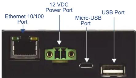
FIG. 2 Rear connectors
The MXT-1901-PAN does not have individual channels on the base of the device to allow passage of cables from underneath the base. Instead, it has one slot at the base to allow options on cable configuration, with channels for securing power, Ethernet, and Micro-USB cables (FIG. 3).
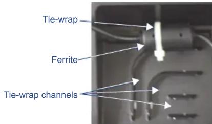
FIG. 3 Tie-wrap for power connector ferrite
Each channel side has slots for attaching tie-wraps to secure each cable. The ferrite on the power cable must be secured with the included tie-wrap during installation to prevent the possibility of the panel not sitting flush on the table.
Wiring Guidelines
The MXT-1901-PAN uses a 12 VDC-compliant power supply to provide power to the panel via the 2-pin 3.5 mm captive wire PWR connector. Use the previously provided power requirement information to determine the power draw. The incoming PWR and GND wires from the power supply must be connected to the corresponding locations within the PWR connector.
NOTE: Apply power to the panel only after installation is complete.
NOTE: Connecting power to the MXT-1901-PAN should be done using the included 2-pin 3.5mm captive wire connector included with the device. This connector is retained within its port with locking screws instead of the pins on each side of standard captive wire connectors, and using force to insert a standard captive wire connector may damage the device.
Wiring a Power Connection
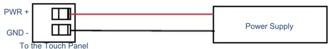
To use the 2-pin 3.5 mm captive wire connector with a 12 VDC-compliant power supply, the incoming PWR and GND wires from the external source must be connected to their corresponding locations on the connector (FIG. 4). The connector uses locking screws to insure a connection to the device, so make sure to insert and tighten the screws before applying power.
flowchart
graph LR
    A["PWR +"] --> B["To the Touch Panel"]
    C["GND -"] --> B
    B --> D["Power Supply"]
FIG. 4 NetLinx power connector wiring diagram
- Insert the PWR and GND wires on the terminal end of the 2-pin 3.5 mm captive wire cable. Match the wiring locations of the +/- on both the power supply and the terminal connector.
- Tighten the clamp to secure the two wires. Do not tighten the screws excessively; doing so may strip the threads and damage the connector.
- Verify the connection of the 2-pin 3.5 mm captive wire to the external 12 VDC-compliant power supply and apply power.
Configuring the MXT-1901-PAN
The MXT-1901-PAN is equipped with a Settings app that allows you to set and configure various features on the panel. For more information on connecting and configuring the MXT-1901-PAN to a network, please refer to the Modero X Series G5 Programming Guide, available at www.amx.com.
Accessing the Settings App
To access the Settings app on the MXT-1901, press and hold the Sleep Button (FIG. 1) on the top of the panel for 3 seconds. The user will be prompted to release the button to enter the Settings app.
Accessing the NetLinx Subpage
- From the Settings app page, select NetLinx. This opens a password keypad.
- Enter the panel password into the keypad (the default is 1988) and select OK to access the subpage.
Setting the Panel's Device Number and Device Name
In the NetLinx subpage:
- Press Device Number to open the NetLinx editing window.
- Enter a unique Device Number assignment for the panel and press OK.
- Enter a unique Device Name assignment for the panel and press OK.
Accessing the Ethernet Subpage
- From the Settings app, select Ethernet. This opens a password keypad.
- Enter the panel password into the keypad (the default is 1988) and select OK to access the page.
Connecting to a Master
The panel requires that you establish the type of connection you want to make between it and your Master.
In the NetLinx page:
- Press Mode to toggle through the available connection modes:
Connection Modes
| Mode | Description Procedures | |
| Auto | The device connects to the first master that responds.This setting requires that you set the System Number. | Setting the System Number:1. Select Master System Number to open the keypad.2. Set your Master System Number and select OK. |
| URL | The device connects to the specific IP of a master via a TCP connection.This setting requires that you set the Master's IP. | Setting the Master IP:1. Select the Master IP number to open the keyboard.2. Set your Master IP and select OK. |
| Listen | The device "listens" for the Master to initiate contact.This setting requires you provide the master with the device's IP. | Confirm device IP is on the Master URL list. You can set the Host Name on the device and use it to locate the device on the master. Host Name is particularly useful in the DHCP scenario where the IP address can change. |
- If you have enabled password security on your Master, you need to set the username and password within the device.
a. Select Username to open the NetLinx editing window.
b. Set your Username and Master Password.
e. Click OK to return to the NetLinx page.
Configuring the Panel to a Network
The first step is to configure the panel's communication parameters. This only configures the panel to communicate with a network, and it is still necessary to tell the panel with which Master it should be communicating.
Network Communication With a DHCP Address
In the Ethernet subpage:
- Toggle the DHCP/Static field to open the DHCP/Static window. DHCP is the default setting. This action causes all fields on the Ethernet subpage (other than Host Name) to be greyed-out.
- Select Host Name to open the Host Name window. Enter the new host name and click OK.
Network Communication with a Static Address
In the Ethernet subpage:
- Toggle the DHCP/Static field to open the DHCP/Static window.
- Select Static in the window. This opens the Static IP editing window.
- Click on any field to open either a keypad (for numeric entries) or keyboard (for alphanumeric entries). To minimize the keypad/keyboard, click the two downward-pointing arrows at the bottom right corner of the screen.
- Enter your network's information in the Static IP editing window. To move from field to field, simply press the next field you wish to edit.
- When finished, click OK to save your changes and return to the Ethernet subpage.