NXD-700i - Skærm AMX - Gratis brugsanvisning og manual
Find enhedens vejledning gratis NXD-700i AMX i PDF-format.

Brugerspørgsmål om NXD-700i AMX
0 spørgsmål om dette apparat. Besvar dem du kender, eller stil dit eget.
Stil et nyt spørgsmål om dette apparat
Download vejledningen til din Skærm i PDF-format gratis! Find din vejledning NXD-700i - AMX og tag din elektroniske enhed tilbage i hånden. På denne side er alle dokumenter nødvendige for brugen af din enhed offentliggjort. NXD-700i af mærket AMX.
BRUGSANVISNING NXD-700i AMX
Overview
The NXD-700i (FG2258-10) is an incredibly versatile user interface, combining a sleek, compact size, Wall/Flush Mount flexibility and the ability to create a high quality digital home/office intercom network or to make/receive digital local, long distance and international telephone calls.
Simply add the AMX SIP Communications Gateway (FG2182-0x) for calls that sound incredibly clear.
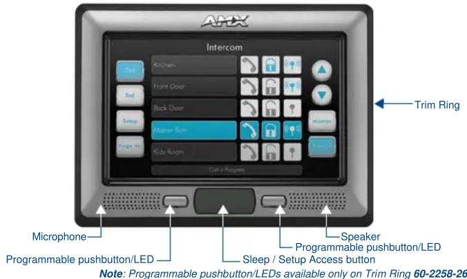
FIG. 1 NXD-700i (shown with Trim Ring 60-2258-26)
ATTENTION!
Verify you are using the latest NetLinx Master and Modero touch panel firmware (available from www.amx.com). Verify the TPDesign4 program being used is Version 2.6 or higher, and download the latest G4 Support Files from www.amx.com.
Specifications
NXD-700i Specifications
| Dimensions (HWD): | |
| NXD-700i(Faceplate included) | 5.93" x 7.87" x 3.28" (15.06 cm x 20.00 cm x 8.33 cm) |
| CB-TP7 (optional Rough-In Box) | 5.47" x 7.23" x 3.40" (13.90 cm x 18.40 cm x 8.64 cm) |
| Power Requirements • PoE Powered - No local power supply needed• Max power draw: 5.5W | |
| Memory: • 128 MB SDRAM• 256MB integrated Flash Memory (not upgradeable - factory programmed) | |
| Weight: 1lb (0.45kg) | |
| Panel LCDParameters: | • Aspect ratio: 16 x 9• Brightness (luminance): 300 cd/m2• Contrast ratio: 400:1• Display colors: 256 thousand colors (18-bit color depth)• Dot/pixel pitch: 0.19 mm• Panel type: TFT Color Active-Matrix• Screen Resolution: 800 x 480 pixels (HV) @ 60 Hz frame frequency |
| Active Screen Area: 6.00" x 3.60" (15.24cm x 9.14cm) | |
| Viewing Angle: Up/Down/Left/Right: 70/60/70/70 | |
| IR Reception Angle: • Horizontal: + 50° (left and right from center)• Vertical: + 30° (up and down from center) | |
| Supported Audio Sample Rates | 48000Hz, 44100Hz, 32000Hz, 24000Hz, 22050Hz, 16000Hz, 12000Hz, 11025Hz, and 8000Hz |
| Intercom Full duplex VoIP capabilities | |
| Video Capabilities: Supports DynaMoTM (M-JPEG), including DynaMo Resource (enhanced M-JPEG) Images. Refer to the TPDesign4 online help and NXD-700i / NXT-CA7 Operation/Reference Guide for details on configuring DynaMo and DynaMo Resource Images. | |
| Front Panel: • Light Sensor: Photosensitive light detector for automatic adjustment of the panel brightness• Motion Sensor (PIR): Proximity Infrared Detector to wake the panel when panel is approached• Front Bezel Button: Provides both access to the setup and calibration pages and toggles the panel between “sleep” or “wake” state. This button is also user-programmable.• Microphone: Frequency response of 300 to 3400Hz; used for intercom applications.• Speaker: Output of 4Ohm, 2 Watt, with a 300Hz low cutoff frequency | |
NXD-700i Specifications (Cont.)
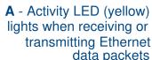
| Side Panel Connectors | Ethernet 10/100 Port: RJ-45 port for 10/100 Mbps communication.The Ethernet port automatically negotiates the connection speed (10 Mbps or 100 Mbps), and whether to use half duplex or full duplex mode.Power is supplied through Power Over Ethernet (PoE).NXD-700i panels communicate with the NetLinx Master using the ICSP protocol over Ethernet.LEDs show communication activity, connections, speeds, and mode information:L/A- link /activity - Yellow LED lights On when Ethernet cables are connected and terminated correctly and then blinks when receiving Ethernet data packets.SPD-speed - Green LED lights On when the connection is 100 Mbps and turns off when the speed is 10 Mbps.Mini-USB Connector: 5-pin Mini-USB connector used for programming, firmware update, and touch panel file transfer between the PC and the target panel.The connector is also used for providing audio output for external speakers. |
| Operating /Storage Environments: | Operating Temperature: 0^ C ( 32^ F) to 40^ C ( 104^ F)Operating Humidity: 20% - 85% RHSstorage Temperature: -20^ C ( -4^ F) to 60^ C ( 140^ F)Storage Humidity: 5% - 85% RH |
| Certifications: • FCC Par | 15 Class B and CEIEC60950RoHS |
| Included Accessories: | Installation Kit for NXD-700i panels (KA2258-02):- 4 Phillips-head screws (#4-40 x 0.250 Black) (80-0112)- 3 Drywall clips (62-5924-05)- 3 #6 sheet metal screws (80-0192)Trim Ring with button openings (60-2258-26)Trim Ring without button openings (60-2258-25) |
| Other AMX Equipment: | NXA-RK7 Rack Mount Kit (FG2904-53)CB-TP7 Rough-In Box (FG035-10)PS-POE-AF PoE Injector (FG423-80)CC-USB Type-A to Mini-B5-wire programming cable (FG10-5965)USB to Headphone Adaptor (FG5966-23)AMX SIP Communications Gateway (FG2182-0x) |
Installing the NXD-700i
Consult the NXD-700i Touch Panels Operation/Reference Guide for the various supported installation methods and dimensions.
Panel Connectors
FIG. 2 shows the connectors located on the NXD-700i:
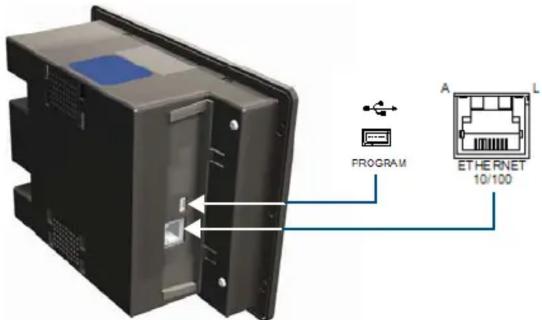
FIG. 2 Connector layout on the NXD-700i
- The mini-USB port is used both for programming the touch panel and for audio output.
- The mini-USB port automatically detects the presence of a headphone adaptor, allowing the port to be used for headphone connectivity.
Note: For more information on connection and use of the Panel Connectors, as well as information on programming and headphone connectivity, please refer to the NXD-700i Operation/Reference Guide, available at www.amx.com.
Ethernet/RJ-45 Port: Connections and Wiring
FIG. 3 describes the blink activity for the Ethernet 10/100 Base-T RJ-45 connector and cable.
The Ethernet cable is connected to the rear of Table Top and side of the Wall Mount panels.
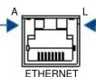
L - Link LED (green) lights when the Ethernet cables are connected and terminated correctly.
FIG. 3 Ethernet connector (showing communication and connection LEDs)
Ethernet RJ-45 Pinouts and Signals
| Pin Signals Connections Pairing Color | 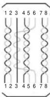 | ||||
| 1 TX + 1 ---- 1 1 ---- 2 Orange- White | |||||
| 2 TX - 2 ---- 2 | Orange | ||||
| 3 | RX + | 3 ---- 3 | 3 ---- 6 | Green-White | |
| 4 no connection 4 ---- 4 | Blue | ||||
| 5 no connection 5 ---- 5 4 ---- 5 | Blue-White | ||||
| 6 | RX - | 6 ---- 6 | Green | ||
| 7 no connection 7 ---- 7 7 ---- 8 | Brown-White | ||||
| 8 no connection 8 ---- 8 | Brown | ||||
Modero Setup and System Connection
The panel is equipped with setup pages that allow you to set and configure various features on the panel. Consult the NXD-700i Touch Panels Operation/Reference Guide for detailed information on the Setup pages.
Accessing the Setup and Protected Setup Pages
- Press the grey Front Setup Access button for 3 or 6 seconds to open the Setup page.
- Press the Protected Setup button.
This invokes a keypad for entry of the password to allow access to the Protected Setup page.
Enter 1988 (the default password), and press Done to proceed.
Note: Clearing Password #5, from the initial Password Setup page, removes the need for you to enter the default password before accessing the Protected Setup page.
Setting the Panel's Device Number
In the Protected Setup page:
- Press the Device Number field to open the Device Number keypad.
Enter a unique Device Number assignment for the panel, and press Done to return to the Protected Setup page. - Press Reboot to reboot the panel, and apply the new Device Number.
Master Connection
The panel requires you to establish the connection between it and your master. In the Protected Setup page:
- Select System Settings
- When using Ethernet, press the listed Mode to toggle through the available connection modes:
Connection Modes
| Mode Description | Procedures | |
| Auto The device connects to the first master that responds.This setting requires you set the System Number. | Setting the System Number:1. Select the System Number to open the keypad.2. Set your System Number select Done. | |
| URL The device connects to the specific IP of a master via a TCP connection.This setting requires you set the Master's IP. | Setting the Master IP:1. Select the Master IP number to the keyboard.2. Set your Master IP and select Done. | |
| Listen | The device "listens" for the master to initiate contact.This setting requires you provide the master with the device's IP. | Confirm device IP is on the Master URL list.You can set the Host Name on the device and use it to locate the device on the master.Host Name is particularly useful in the DHCP scenario where the IP address can change. |
- Select the Master Port Number to open the keypad and change this value. The default setting for the port is 1319.
- Set your Master Port and select Done.
If you have enabled password security on your master you need to set the username and password within the device.
a. Select the blank field Username to open the keyboard.
b. Set your Username and select Done.
c. Select the blank field Password to open the keyboard.
d. Set your Password and select Done.
-
Press the Back button to return to the Protected Setup page.
-
Press the Reboot button to reboot device and confirm changes.
Panel Intercom Configuration
Incorporating an Intercom Capable Panel Into Your NetLinx System
Download the module for the intercom panel from www.amx.com, and include it in your NetLinx project file.
For searching purposes, the module manufacturer is AMX and the model is Intercom.
Advanced Setup
The intercom's advanced setup pages are accessed through the intercom setup pages. The advanced pages allow you to set the panel intercom to be monitored, to monitor other intercom panels, and to name the panel. It is important to name the intercom panel, the name is displayed in other panels' intercom call directory pages.
Consult the NXD-700i Touch Panels Operation/Reference Guide for more intercom setup features.
-
Select the Setup button on your intercom page.
-
On the intercom setup page, press Advanced Setup. This launches the password numeric keypad.
-
Enter the password and press Done. The default password is Password 4 of the panel's firmware Password Setup.
Naming the Panel
In the intercom Advanced Setup page:
- Press in the area under Panel Name. This launches an on screen keyboard.
- Type the name of the panel and press Done. This is the name that is displayed in other panels' intercom call directory pages.
- Press Back to return to the intercom setup pages.
- Press Exit when you are finished.
Note: The Panel Name is also the G4 Web Control Name and can be set via the panel's firmware pages.
Calibrating the Panel
Peel the protective plastic film from the LCD.
Note: If the protective plastic film on the LCD is not removed, the panel may not respond properly to touch points on the LCD nor allow proper screen calibration.
- Press and hold the grey Front Setup Access button (see FIG. 1) for 6 seconds to pass-over the Setup page and access the Calibration setup page.
- Press the crosshairs (on the Calibration page) to set the calibration points on the LCD
- After the "Calibration Successful.." message appears, press anywhere on the screen to continue and return to the Setup page.
Additional Documentation
For more detailed installation, configuration, programming, file transfer, and operating instructions, refer to the NXD-700i Touch Panels Operation/Reference Guide, available online at www.amx.com.
Related Documents
- VisualArchitect Operation/Reference Guide
• G4 PanelBuilder Operation/Reference Guide - TPDesign4 Touch Panel Design Program Operation/Reference Guide