DMM 60 - Måling PCE Instruments - Gratis brugsanvisning og manual
Find enhedens vejledning gratis DMM 60 PCE Instruments i PDF-format.

Brugerspørgsmål om DMM 60 PCE Instruments
0 spørgsmål om dette apparat. Besvar dem du kender, eller stil dit eget.
Stil et nyt spørgsmål om dette apparat
Download vejledningen til din Måling i PDF-format gratis! Find din vejledning DMM 60 - PCE Instruments og tag din elektroniske enhed tilbage i hånden. På denne side er alle dokumenter nødvendige for brugen af din enhed offentliggjort. DMM 60 af mærket PCE Instruments.
BRUGSANVISNING DMM 60 PCE Instruments

www.pce-instruments.com/english www.pce-instruments.com
User Manual
CE
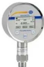
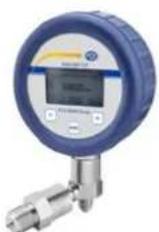
Pressure Gauge PCE-DMM 70 / PCE-DMM 60
1.1 Information on the operating manual
This operating manual contains important information on proper usage of the device. Read this operating manual carefully before installing and starting up the pressure measuring device.
Adhere to the safety notes and operating instructions which are given in the operating manual. Additionally applicable regulations regarding occupational safety, accident prevention as well as national installation standards and engineering rules must be complied with!
This operating manual is part of the device and must be kept at a. for the personnel always accessible location, close to the installation position of the device.
This operating manual is copyrighted. The contents of this operating manual reflect the version available at the time of printing. It has been issued to our best knowledge and belief. However, errors may have occurred. For incorrect statements and their consequences, liability cannot be assumed by PCE Instruments.
- Technical modifications reserved -
1.2 Symbols used
DANGER! - Dangerous situation, which may result in serious or fatal injuries
WARNING! – Potentially dangerous situation, which may result in fatal or serious injuries
CAUTION! - Potentially dangerous situation, which may result in minor injuries
! CAUTION! – Potentially dangerous situation, which may result in damage of objects
NOTE – Tips and information for the user to ensure good conditions for the operation.
1.3 Target group
WARNING! To avoid hazards for the operator and damages of the device, following described instructions have to be worked out by qualified technical personnel.
1.4 Limitation of liability
No liability is assumed and warranty claims are excluded in case of non-observance of the operating manual, improper application, modification of or damage to the device.
1.5 Intended use
- The battery powered digital gauge has been designed for extremely high demands in the sector of calibration and test technology. It can be easily and quickly installed in situ.
- It is in the responsibility of the user to verify whether the chosen device is suitable for the intended application. In case of any doubts, contact our sales department to eliminate any indistinctness. PCE Instruments does not assume any liability for an incorrect selection and its consequences!
WARNING! - Danger through improper usage!
1.6 Package contents
Please verify that all listed parts are undamaged included in the delivery and check for consistency specified in your order.
The batteries are already used. The circuit is interrupted by an insulation foil. Take this before first introduction, see in addition battery change!!
2. Mechanical Installation
2.1 Mounting and safety instructions
WARNING! Mount the device (pressure transmitter module) always in the state without pressure and apart from the display!
WARNING! This device may only be installed by qualified technical personnel who has read and understood the operating manual!
⚠️ WARNING! Do not use the display to tighten or solve to the mechanical connection of the pressure transmitter module!
!Handle this electronic precision measuring device carefully in packed as well as in unpacked condition!
!The device must not be subject to any changes or modifications.
!The device may not be thrown!
!To avoid damaging the diaphragm, remove packaging and protective cap only directly before starting up the device. A delivered protective cap must be stored!
!Place the protective cap on the pressure port again immediately after disassembling.
!Handle the unprotected diaphragm very carefully - it is very sensitive and may be easily damaged.
!Do not use any force when installing the device to prevent damage of the device and the plant!
Take note that no inadmissibly high mechanical stresses occur at the pressure port as a result of the installation, since this may cause a shifting of the characteristic curve or to the damage. This is especially important for very small pressure ranges as well as for devices with a pressure port made of plastic.
In hydraulic systems, position the device in such a way that the pressure port points upward (venting).
Provide a cooling line when using the device in steam lines.
2.2 General Installation steps
- Carefully remove the pressure measuring device from the package and dispose of the package properly.
- Then go ahead as detailed in the specific instructions below.
2.3 Installation steps for DIN 3852
DO NOT USE ANY ADDITIONAL SEALING MATERIALS, LIKE YARN, HEMP OR TEFLON TAPE!
- Check to ensure the proper groove fitting of the o-ring and additionally to ensure no damage to the o-ring.
- Ensure that the sealing surface of the taking part is perfectly smooth and clean. (Rz 3.2)
- Screw the device into the corresponding thread by hand.
- If you have a device with a knurled ring, the transmitter has to be screwed in by hand only.
- Devices with a spanner flat have to be fully tightened with an open-end Devices (G1/4": approx. 5 Nm; G1/2": approx. 10 Nm).
- The indicated tightening torques must not be exceeded!
2.4 Installation steps for EN 837
- Use a suitable seal, corresponding to the medium and the pressure input (e. g. a cooper gasket).
- Ensure that the sealing surface of the taking part is perfectly smooth and clean. (Rz 6.3)
- Screw the device into the corresponding thread by hand.
- Tighten it with a wrench (for G1/4": approx. 20 Nm; for G1/2": approx. 50 Nm).
- The indicated tightening torques must not be exceeded!
2.5 Installation steps for NPT
- Use a suitable seal (e. g. a PTFE-strip).
- Screw the device into the corresponding thread by hand.
- Tighten it with a wrench (for 1/4" NPT: approx. 30 Nm; for 1/2" NPT: approx. 70 Nm).
- The indicated tightening torques must not be exceeded!
2.6 Installation steps for Internal threads M20x1.5 and 9/16" UNF (for DM01-500 HD)
- Screw the high pressure connection into the internal thread of the pressure port and tighten it properly with approx. 160 Nm.
- DANGER! The high pressure tube seals metal-to-metal in the chamfer of the pressure port. No further seal is allowed with this high pressure connection. A wrong installation can cause enormous danger!
3. Connection display with pressure transmitter module
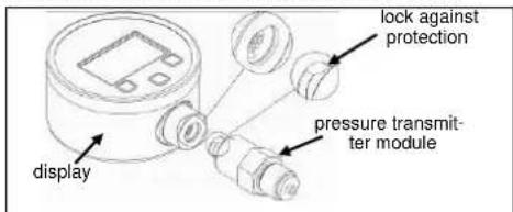
Fig. 1 Lock against protection
Connect display with pressure transmitter module as follows:
- bring together carefully the display with pressure transmit ter module.
- press the display sturdy pressure transmitter module to this engages.
4. Supply / changing the batteries
As soon as in the display the announcement of "battery" is shown, carry out battery change as follows:
- unscrew three fixing screws with a suitable screwdriver.
- take the battery case cap and exchange the batteries 3 x 1.5 V AA (remove the insulation foil before first introduction).
- lock the device after that properly
!An incorrect usage may cause a leak out of batteries and so a damage the device!
!Never combine batteries of different types or old with new ones!
!Make sure that the batteries are connected correctly with the corresponding contacts in the battery tray.
!Never try to charge batteries, demount them, or short-circuit them.
!use only batteries with UL certification
!Keep the batteries away from heat and unshielded flame.
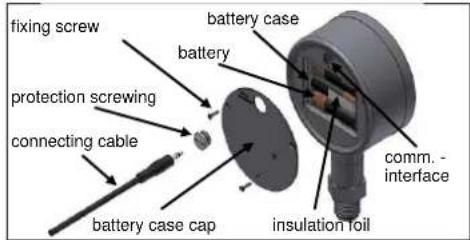
Fig. 2 Battery case cap and communication interface
5. Data logger
The battery powered digital gauge disposes of an integrated data logger. The measuring values stored away in the device can be selected above the communication interface by means of software.
5.1 PC - connection
Connect device with a computer as follows: - unscrew the protective screwing of the communication interface with a suitable slit screwdriver.
- connect the handle plug of the connecting cable (included in delivery) with the interface socket of the device. Connect the side with the USB plug with a free USB connection on the computer.
- install the COM driver and data logger software.
- after the use, disconnect the connection and lock the protection screwing again properly.
6. Initial start-up
remove the insulation foil before first introduction.
WARNING! Before start-up, the user has to check for proper installation and for any visible defects.
WARNING! The device can be started and operated by authorized personnel only, who have read and understood the operating manual!!
WARNING! The device has to be used within the technical specifications, only (compare the data in the data sheet)!
7. Placing out of service
WARNING! When dismantling the device, it must always be done in the depressurized and currentless condition! Check also if the medium has to be drained off before dismantling!
WARNING! Depending on the medium, it may cause danger for the user. Comply therefore with adequate precautions for purification.
8. Operation
8.1 Operating and display elements
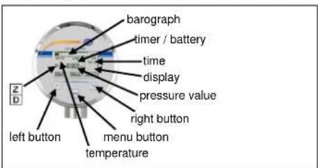
Fig. 3 Display and operating foil
The display of the measuring value as well as configuring the single parameters occurs menu-steered about a LC display capable of graphic arts. The single functions are regulated on the basis of three-front-sided arranged push buttons.
The menu system is closed, thereby one can "browse" forward as well as backward by the single setting menus to reach to the desired setting point.
8.2 Structure of the menu system
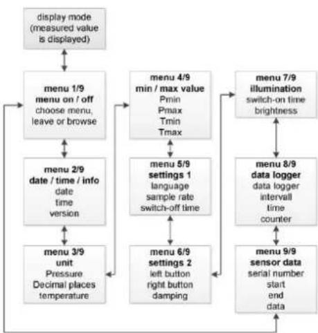
flowchart
graph TD
    A["display mode (measured value is displayed)"] --> B["menu 1/9 menu on / off choose menu, leave or browse"]
    B --> C["menu 2/9 date / time / info date time version"]
    C --> D["menu 3/9 unit Pressure Decimal places temperature"]
    D --> E["menu 4/9 min / max value Pmin Pmax Tmin Tmax"]
    E --> F["menu 5/9 settings 1 language sample rate switch-off time"]
    F --> G["menu 6/9 settings 2 left button right button damping"]
    G --> H["menu 7/9 illumination switch-on time brightness"]
    H --> I["menu 8/9 data logger data logger interval time counter"]
    I --> J["menu 9/9 sensor data serial number start end data"]
9. Disposal
The device must be disposed according to the European Directives 2002/96/EG and 2003/108/EG (on waste electrical and electronic equipment) Waste of electrical and electronic equipment may not be disposed by domestic refuse!

⚠ WARNING! Depending on the measuring medium, deposit on the device may cause danger for the user and the environment. Comply with adequate precautions for purification and dispose of it properly.
10. Warranty conditions
The warranty conditions are subject to the legal warranty period of 24 months from the date of delivery. In case of improper use, modifications of or damages to the device, we do not accept warranty claims. Damaged diaphragms will also not be accepted. Furthermore, defects due to normal wear are not subject to warranty services
11. Declaration of conformity / CE
The delivered device fulfils all legal requirements. The applied directives, harmonised standards and documents are listed in the EC declaration of conformity. Additionally, the operational safety is confirmed by the CE sign on the manufacturing label. warranty services.
12. Maintenance
In principle, this device is maintenance-free. If desired, the housing of the device can be cleaned when switched of using a damp cloth and non-aggressive cleaning solutions.
With certain media, however, the diaphragm may be polluted or coated with deposit. It is recommended to define corresponding service intervals for control. After placing the device out of service correctly, the diaphragm can usually be cleaned carefully with a non-aggressive cleaning solution and a soft brush or sponge. If the diaphragm is calcified, it is recommended to send the device to PCE Instruments for decalcification. Please read therefore the chapter "Repair" below.
A false cleaning of the device can cause an irreparable damage on the diaphragm. Therefore never use pointed objects or pressured air for cleaning the diaphragm.
13. Service / Repair
We recommend that the instrument is regularly recalibrated by PCE Instruments, with time intervals of approx. 12 months. Before you return, the device has to be cleaned carefully and packed shatter-proofed. You have to enclose a notice of return with detailed defect description when sending the device. Contact PCE Instruments to ask for this form. If your device came in contact with harmful substances, a declaration of decontamination is additionally required. Should you dispatch a device without a declaration of decontamination and if there are any doubts in our service department regarding the used medium, repair will not be started until an acceptable declaration is sent.
- Menu list
| Switch on | The device can be switched on with every button (left button, menu button, right button). |
| Menu 1/9on / off | By push the menu button the operating mode will be selected / left / ("Menu" / "Exit"). |
| Menu 2/9date / time / info | Setting of topical time and the topical date. Software version will be shown. |
| Menu 3/9Units | Setting of the pressure unitadjustable units: [bar], [mbar], [PSI], [inHg], [cmHg], [mmHg], [hPa], [kPa], [MPa], [mmH2O], [mH2O], [kg/cm ^2 ] or [user] (the user-defined unit can be programmed only by means of the software BD|LOG), a conversation of all pressure related parameters is carried out automaticallySetting of decimal placesadjustable decimal place: standard [Std], [+1], [+2]Setting of the temperature unitthe unity is not adjustable. Factory setting [°C] |
| Menu 4/9Min / Max Values | Language: Setting of user languages German [DE] or English [EN]Measuring rate: here it is put how often the measurement is carried out and is indicated.Possible settings are: a measurement per second [1/sec]or two measurements per second [2/sec]Auto Off Time: Setting of the automatic switch off in minutes. The automatic switch off is able in steps from [1 min], [2 min], [3 min], [4 min] or [5 min]; 30 seconds before switching off the timer is activated and indicated in the display.By the option [Off] the device can be deactivated. After deactivation, the precision digital gauge is in the continuous operation. |
| Menu 5/9Configuration 1 | Language: Setting of user languages German [DE] or English [EN]Measuring rate: here it is put how often the measurement is carried out and is indicated.Possible settings are: a measurement per second [1/sec]or two measurements per second [2/sec]Auto Off Time: Setting of the automatic switch off in minutes. The automatic switch off is able in steps from [1 min], [2 min], [3 min], [4 min] or [5 min];30 seconds before switching off the timer is activated and indicated in the display.By the option [Off] the device can be deactivated. After deactivation, the precision digital gauge is in the continuous operation. |
| Menu 6/9Configuration 2 | Button settings: left button / right buttonLeft Button: function configurations: [Min], [Light], [Zero], [Reset]Right Button: function configurations: [Max], [Light], [Zero], [Reset]Function descriptions:- [Min] / [Max] minimum / maximum pressure value will be showed-[Light] the display backlight is activated-[Zero] the zero point is automatically put, in the display appears-[Reset] the opposed zero is put back goes outDamping: the damping can be put in 1 second steps between [1 sec] and [10 sec] or be deactivated by option [Off] |
| Menu 7/9Backlight | Backlight settings of displayOn Time: the backlight duration can be put in 1 second steps between [1 sec] and [10 sec] or be deactivated by option [Off]Brightness: the brightness can be put into 5% of steps between [0%] and [100%] |
| Menu 8/9Data Logger | Data Logger configurationData Logger: the following settings are possible: linearly [Linear] (value admission to the counter level 8500 is reached), cyclically [Loop] (after the value is reached in 8500, the data logger automatically begins the values once more to grasp and, besides, headlines the old values) or [Off](in the display appears if the data logger is activated and goes out if the data logger is off)Interval: Intervals to the memory of the measuring values (pressure / temperature) second [1-99 sec], minute [1-99 min], hour [1-99 hour] or day [1-99 days]Time: Measuring value admission: in which time the measuring value admission should occur (is only efficiently for the setting "daily").Counter: Number of the grasped measuring values is indicated. Maximum value: 8500(Put back counter reading: menu point with "Edit" select → button "Next" four times operate → button ">>" operate. There appears the question "Reset?" → once more operate the button ">>>". It seems "Sure?" additional confirmation whether the value should be reset → repeated confirming with the button ">>" reset the grasped measuring values. Display announcement ("Counter: 0/8500") |
| Menu 9/9Sensor Data | [SN:] the standard number is indicated [Upper] Measuring area end[Lower] Measuring area beginning [Date] Production dateValues are put by factory and are not adjustable. |
| Error | Display "No Sensor": display and pressure sensor module are separated. |
- Left Button: if is a functional button and can be configured in the menu 6. Light-, Zero-, Reset- or Min- function can be assigned to the button. The configured function is active in the display mode. Hold the button during approx. 2 seconds to activate the function. In the operating mode you move in the menu system backward “<<” or you reduce the set value.
- Right Button: if is a functional button and can be configured in the menu 6. Light-, Zero-, Reset- or Max- function can be assigned to the button. . Hold the button during approx. 2 seconds to activate the function. In the operating mode you move in the menu system forward ">>" or you raise the set value.
- Menu-Button: by pressure of this button "menu" you reach in the operating mode; moreover, she serves for the choice of the single menu points "Edit" or in the confirmation the opposed worth "Next".
To the configuration of the single menu points the desired menu point is to be put with the help of the left button "<<" or right button ">>". Confirm this afterwards with the menu button "Edit" the menu point is marked and the configuration can begin.
To store an opposed value the menu button "Next" must be also pressed. To leave the menu press the menu button so often to the mark of the single menu point and choose with the left button "<<" or right button ">>" the menu 1 and press the menu button once more "Exit". The operating mode will also leave after approx. 1 min automatically.
Changes become first after activity of the menu button "Next" and after abandonment of the menu point effective. With the abandonment of the whole menu system the opposed parameters are checked once again in dependence to each other and concerning the characteristics of the device. With the configuration of the unity a conversion of the measuring area occurs in the new unity only after abandonment of the menu system. According to pressure area not all units can be also used if necessary.