
UTE 2500-24 - Termostat Eberle - Gratis brugsanvisning og manual
Find enhedens vejledning gratis UTE 2500-24 Eberle i PDF-format.

Brugerspørgsmål om UTE 2500-24 Eberle
0 spørgsmål om dette apparat. Besvar dem du kender, eller stil dit eget.
Stil et nyt spørgsmål om dette apparat
Download vejledningen til din Termostat i PDF-format gratis! Find din vejledning UTE 2500-24 - Eberle og tag din elektroniske enhed tilbage i hånden. På denne side er alle dokumenter nødvendige for brugen af din enhed offentliggjort. UTE 2500-24 af mærket Eberle.
BRUGSANVISNING UTE 2500-24 Eberle
468 931 014 352
D
Montage- und Bedienungsanleitung
UTE 2100
UTE 2500
UTE 2500-24

Achtung!
Das Gerät darf nur durch einen Elektrofachmann geöffnet und gemäß dem Schaltbild am Gerät bzw. dieser Anleitung installiert werden. Dabei sind die bestehenden Sicherheitsvorschriften zu beachten.
Um die Anforderungen der Schutzklasse II zu erreichen, müssen entsprechende Installationsmaßnahmen ergriffen werden.
Dieses unabhängig montierbare elektronische Gerät dient der Regelung der Temperatur ausschließlich in trockenen und geschlossenen Räumen, mit üblicher Umgebung. Dieses Gerät entspricht der DIN EN 60730, es arbeitet nach der Wirkungsweise 1C.
1. Verwendungsbereich
Die elektronischen Temperaturregler UTE 2100 und UTE 2500 können zur Regelung der Boden- und Raumtemperatur verwendet werden.
2. Montageort
- Der Regler soll an einer Stelle im Raum montiert werden, die für die Bedienung leicht zugänglich ist.
- Montagehöhe: ca. 1,5 m über dem Fußboden.
- Die Installation an einer Innenwand ist zu bevorzugen. Vermeiden Sie Außenwände und Zugluft von Fenstern und Türen.
- Achten Sie darauf, dass die normale Konvektionsluft des Raumes den Regler ungehindert erreicht. Der Regler soll daher nicht innerhalb von Regalwänden oder hinter Vorhängen und ähnlichen Abdeckungen montiert werden.
- Fremdwärme beeinflusst die Regelgenauigkeit nachteilig.
- Direkte Sonneneinstrahlung, die Nähe von Fernseh-, Rundfunk- und Heizgeräten, Lampen, Kaminen und Heizungsrohren muss vermieden werden.
• Montage in Unterputzdose 60mm
3. Elektrischer Anschluss
Achtung!
Stromkreis spannungsfrei schalten
Anschluss in folgenden Schritten:
• Abziehen des Temperatur-Einstellknopfes
- Lösen der Befestigungsschraube
• Abnehmen des Gehäuseoberteils
- Anschluss gemäß Schaltbild (s. Gehäuseboden oder Schaltbild in dieser Anleitung.)
• Montage in umgekehrter Folge
Achtung!
Montage nur in nichtleitenden (Kunststoff-) Unterputzdosen.
Kurzbeschreibung im Schaltbild
L = Außenleiter (Phase)
N = Neutralleiter (früher Mp)
① = Anschluss für Uhrsignal zur Temperaturabsenkung
SSS = Lastanschluss Heizen
◇ = Lastanschluss Kühlen
H/C> = Anschluss für Heizen/Kühlen Eingangssignal
Anzeigelampe rot: Regler fordert Wärme an Anzeigelampe grün: Temperaturabsenkung ein Anzeigelampe blau: Kühlbetrieb aktiv
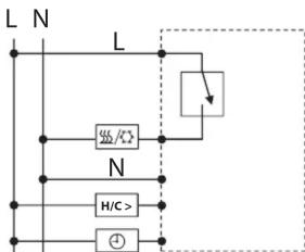
4. Schaltbild
UTE 2100


UTE 2500

flowchart
graph TD
    A["L"] --> B["Switch"]
    C["N"] --> D["Capacitor /×"]
    E["H/C>"] --> F["Ground"]
    G["Input"] --> H["Ground"]

UTE 2500-24

flowchart
graph TD
    A["AC1"] --> B["AC2"]
    B --> C["Switch"]
    C --> D["AC1"]
    B --> E["AC2"]
    E --> F["H/C>"]
    F --> G["+"]
    G --> H["Ground"]

- Technische Daten
| Bestellbezeichnung | UTE 2100 | UTE 2500 | UTE 2500-24 |
| Spannungsversorgung | 230V AC 50 Hz (207 ... 253 V) | 230V AC 50 Hz (207 ... 253 V) | 24V AC 50 Hz (21,6V ... 26,4V) |
| Temperatureinstellbereich | 5°C ... 30°C | 5°C ... 30°C | 5°C ... 30°C |
| Ausgang | TRIAC | TRIAC | TRIAC |
| Anzahl schaltbare | 5 | 5 | 5 |
| Stellantriebe | (3 W elektrothermisch) | (3 W elektrothermisch) | (3 W elektrothermisch) |
| Schaltstrom dauernd | 0 ... 65 mA | 0 ... 65 mA | 0 ... 65 mA |
| Einschaltstrom(kurzzeitig für 2 s) | max. 5 A | max. 5 A | max. 5 A |
| Regelalgorithmus | PWM | PWM | PWM |
| PWM-Zykluszeit | 10 min | 10 min | 10 min |
| Temperaturabsenkung* | 3,5°C | 3,5°C | |
| Frostschutz | 5°C | 5°C | 5°C |
| Anzeige LED | Rot: HeizenGrün: Temp. Absenkung einBlau: Kühlen | Rot: HeizenGrün: Temp. Absenkung einBlau: Kühlen | |
| Bereichseinengung | Im Einstellknopf integriert | Im Einstellknopf integriert | Im Einstellknopf integriert |
| Umgebungstemperatur | 0 ... 45°C | 0 ... 45°C | 0 ... 45°C |
| Lagerung | -25 ... 60°C | -25 ... 60°C | -25 ... 60°C |
| Überspannungskategorie | III | III | III |
| Bemessungs-Stoßspannung | 4 kV | 4 kV | 4 kV |
| Spannung und Strom für Zwecke der EMV-Störaussendungsprüfung | 230 V, 0,1 A | 230 V, 0,1 A | 24 V, 0,1 A |
| Schutzklasse | II | II | III |
| Schutzart | IP30 | IP30 | IP30 |
| Softwareklasse | Klasse A | Klasse A | Klasse A |
| Verschmutzungsgrad | 2 | 2 | 2 |
| Temperatur für Kugeldruckprüfung | 75°C | 75°C | 75°C |
| Gewicht | 36 g | 39 g | 35.1 g |
| Energie-Klasse(nach EU 811/2013, 812/2013,813/2013, 814/2013) | IV = 2 % | IV = 2 % | IV = 2 % |
* im Kühlbetrieb wird die Solltemperatur um 3,5°C Wert erhöht.
Jumper:
Über die Jumper (Steckbrücken) kann eingestellt werden ob der Regler Stellantriebe „stromlos geschlossen“ (NC) oder „stromlos offen“ (NO) ansteuert. Je nach Einstellung ist das Ausgangssignal wie folgt:
NC: 230 V/24 V → Heizen/Kühlen Ein 0 V → Heizen/Kühlen Aus
NO: 230 V/24 V → Heizen/Kühlen Aus 0 V → Heizen/Kühlen Ein
6. Maße
6.1 Variante 55 x 55

6.2 Variante 50 x 50

7. Einengen des
Temperatureinstellbereiches:
Werkseitig ist der Temperaturregler auf den maximalen Einstellbereich von 5 ... 30 °C eingestellt (siehe Bild 1).
Im Einstellknopf befinden sich 2 Einstell ringe. Mit diesen kann der Temperatureinstellbereich beliebig eingestellt werden.

Bild 1:
Einengen des Temperatureinstellbereiches

Dieses Produkt darf nicht über den Hausmüll entsorgt werden. Bitte nur in speziellen Einrichtungen für Elektronikschrott entsorgen. Erkundigen Sie sich bei den örtlichen Behörden zur Recycling Beratung.
468 931 014 352
GB
Installation and
Operating Instructions
UTE 2100
UTE 2500
UTE 2500-24

Important!
The device may only be opened by an electrically skilled person and must be installed as shown on the circuit diagram on the device and in these instructions. The existing safety regulations must be followed.
The relevant installation measures must be taken to achieve the requirements of protection class II. This independently mountable electronic device is used to control the temperature in dry and enclosed rooms only, with normal environment. This device conforms to EN 60730, it operates according to type 1C action.
1. Area of use
The UTE 2100 and UTE 2500 electronic temperature controllers can be used to control the floor and room temperature.
2. Installation site
- The controller should be mounted in a place in the room that is easy to access for operation.
- Mounting height: approx. 1.5m above the floor.
- Preference should be given to installation on an internal wall. Avoid external walls and draughts from windows and doors.
- Ensure that the room's normal convection air reaches the controller freely without restriction. The controller should therefore not be mounted inside shelf units or behind curtains and similar coverings.
- Extraneous heat has a negative influence on the control accuracy.
- Direct sunshine, proximity to televisions, radios and heaters, lamps, stoves and heating pipes must be avoided.
• Install in flush-mounting box 60mm
3. Electrical connection
Important!
Disconnect the electric circuit from the mains
Connection in the following steps:
• Pull off the temperature control knob
- Undo the fastening screw
- Remove the top part of the housing
- Connect as shown on the circuit diagram (see bottom of housing or circuit diagram in these instructions.)
• Install in the reverse order
Important!
Mount in non-conductive (plastic)
flush-mounting boxes only.
Abbreviations used in the circuit diagram
L = Outer conductor (phase)
N = Neutral conductor (previously Mp)
= Connection for clock signal for temperature reduction
SSS = Heating load connection
☀️ = Cooling load connection
H/C> = Connection for heating/cooling input signal
Red indicator lamp: Controller requests heat
Green indicator lamp: Temperature reduction on
Blue indicator lamp: Cooling mode is active
4. Circuit diagram
UTE 2100


UTE 2500
flowchart
graph TD
    A["L"] --> B["Switch"]
    C["N"] --> D["H/C>"]
    E["+"] --> F["Ground"]
    G["Switch"] --> H["Output"]
    style A fill:#f9f,stroke:#333
    style C fill:#f9f,stroke:#333
    style E fill:#f9f,stroke:#333
    style G fill:#f9f,stroke:#333

UTE 2500-24

flowchart
graph TD
    A["AC1"] --> B["AC2"]
    B --> C["H/C>"]
    C --> D["Switch Symbol"]
    D --> E["AC1/AC2"]
    E --> F["Output"]
    style A fill:#f9f,stroke:#333
    style B fill:#ccf,stroke:#333
    style C fill:#cfc,stroke:#333
    style D fill:#fcc,stroke:#333
    style E fill:#ffc,stroke:#333

- Technical Data
| Order designation | UTE 2100 | UTE 2500 | UTE 2500-24 |
| Voltage supply | 230 V AC 50 Hz (207 ... 253 V) | 230 V AC 50 Hz (207 ... 253 V) | 24 V AC 50 Hz (21.6V ... 26.4V) |
| Temperature setting range | 5°C ... 30°C | 5°C ... 30°C | 5°C ... 30°C |
| Output | TRIAC | TRIAC | TRIAC |
| Number of switchable actuators | 5(3 W electrothermal) | 5(3 W electrothermal) | 5(3 W electrothermal) |
| Continuous switching current | 0 ... 65 mA | 0 ... 65 mA | 0 ... 65 mA |
| Inrush current(short-term for 2 s) | max. 5 A | max. 5 A | max. 5 A |
| Control algorithm | PWM | PWM | PWM |
| PWM cycle time | 10 min | 10 min | 10 min |
| Temperature reduction* | 3.5°C | 3.5°C | |
| Frost protection | 5°C | 5°C | 5°C |
| LED display | Red: HeatGreen: Temp. reduction onBlue: Cool | Red: HeatGreen: Temp. reduction onBlue: Cool | |
| Range restriction | Integrated in the control knob | Integrated in the control knob | Integrated in the control knob |
| Ambient temperature | 0 ... 45°C | 0 ... 45°C | 0 ... 45°C |
| Storage | -25 ... 60°C | -25 ... 60°C | -25 ... 60°C |
| Overvoltage category | III | III | III |
| Rated pulse voltage | 4 kV | 4 kV | 4 kV |
| Voltage and current for EMC emission testing purposes | 230 V, 0.1 A | 230 V, 0.1 A | 24 V, 0.1 A |
| Protection class | II | II | III |
| Degree of protection | IP30 | IP30 | IP30 |
| Software class | Class A | Class A | Class A |
| Pollution degree | 2 | 2 | 2 |
| Temperature for ball indentation test | 75°C | 75°C | 75°C |
| Weight | 36 g | 39 g | 35.1 g |
| Energy class(to EU 811/2013, 812/2013,813/2013, 814/2013) | IV = 2 % | IV = 2 % | IV = 2 % |
* in cooling mode the setpoint temperature is increased by 3.5 °C.
Jumper:
The jumpers (links) can be used to set whether the controller operates "normally closed" (NC) or "normally open" (NO) actuators. Depending on the setting, the output signal is as follows:
NC: 230 V/24 V → Heat/Cool On
0 V → Heat/Cool Off
NO: 230 V/24 V → Heat/Cool Off
0 V → Heat/Cool On
6. Dimensions
6.1 55 x 55 version

6.2 50 x 50 version

7. Restricting the temperature setting range:
The temperature controller is set in the factory to the maximum setting range of 5 ... 30 °C (see Figure 1).
There are 2 adjusting rings in the control knob. These can be used to set the temperature setting range as required.

Figure 1: Restricting the temperature setting range

This product should not be disposed of with household waste. Please recycle the products where facilities for electronic waste exist. Check with your local authorities for recycling advice.


- Montage- und Bedienungsanleitung
- Achtung!
- Verwendungsbereich
- Montageort
- Elektrischer Anschluss
- Stromkreis spannungsfrei schalten
- Kurzbeschreibung im Schaltbild
- Schaltbild
- Jumper:
- Maße
- Einengen des
- Temperatureinstellbereiches:
- Installation and
- Operating Instructions
- UTE 2100
- UTE 2500
- UTE 2500-24
- Important!
- Area of use
- Installation site
- Electrical connection
- Disconnect the electric circuit from the mains
- Abbreviations used in the circuit diagram
- Circuit diagram
- Dimensions
- Restricting the temperature setting range:
Mærke : Eberle
Model : UTE 2500-24
Kategori : Termostat