
RD-550 - Kassetteafspiller ROTEL - Gratis brugsanvisning og manual
Find enhedens vejledning gratis RD-550 ROTEL i PDF-format.

Brugerspørgsmål om RD-550 ROTEL
0 spørgsmål om dette apparat. Besvar dem du kender, eller stil dit eget.
Stil et nyt spørgsmål om dette apparat
Download vejledningen til din Kassetteafspiller i PDF-format gratis! Find din vejledning RD-550 - ROTEL og tag din elektroniske enhed tilbage i hånden. På denne side er alle dokumenter nødvendige for brugen af din enhed offentliggjort. RD-550 af mærket ROTEL.
BRUGSANVISNING RD-550 ROTEL
OWNER'S MANUAL
Quality. Uncompromised.
ROTEL®
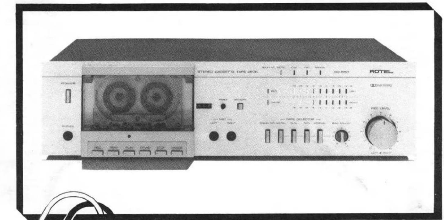
METAL CAPABILITY STEREO CASSETTE DECK
RD-55O
WARNING: TO PREVENT FIRE OR SHOCK HAZARD, DO NOT EXPOSE THIS APPLIANCE TO RAIN OR MOISTURE

Write your SERIAL NUMBER here. The number is located near the name plate on the unit's rear panel.
THE ROTEL CO., LTD.
1-36-8 Ohokayama, Meguro-ku, Tokyo, Japan
INTRODUCTION
We at Rotel want to thank you for purchasing our audio product. Rotel audio products are designed to use the latest electronic technology, and they incorporate our long experience as a specialist manufacturer of audio equipment. We are confident that you will find satisfaction in the high quality sound and top performance, and that you will find pleasure in the functional beauty achieved through human-engineering concept. Before starting operation, please read this instruction manual thoroughly and acquaint yourself with the proper mode of using the unit and all its connections.
We hope you will enjoy top-notch performance for many years to come.
POWER SUPPLY CONNECTION
For power the unit requires the normal house electrical current (AC). You may simply plug the unit into a wall outlet, or into your amplifier's switched or unswitched AC outlet. If it is plugged into a switched outlet, by leaving the power switch of the unit on, you will be able to maintain switching control for the RD-550 with your amplifier. If it is connected to an unswitched outlet, like connecting to a wall outlet you must use the RD-550's own power switch for switching control.
CAUTION: Do not apply power without first making sure the proper connections are completed. If you live in U.K. and your unit comes with 2-core cord without a plug, be sure to read the exclusive caution for U.K.
INSTALLATION
Be sure to place the unit in a level and flat place where it is free from humidity, vibration, high temperature and not exposed to direct sunlight. Be careful not to place the unit in a highly enclosed place such as near a wall or on a bookshelf. A poor ventilation will cause undesirable effects to the unit.
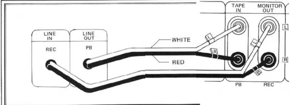
CONNECTION TO INTEGRATED AMPLIFIER
Two pairs of RCA cords for LINE IN/OUT extend out from the rear panel of the cassette deck. The cord from the LINE IN terminals of the deck should be plugged into the TAPE MONITOR OUT terminal of the amplifier, and the cord from LINE OUT terminal to the TAPE MONITOR IN terminal. RCA cords with white plugs are for left channel (L) connection, and cords with red plugs are for right channel (R).
AMPLIFIER (REAR PANEL)
CASSETTE DECK
EXCLUSIVE NOTE FOR U.K.
If your unit comes with a 2-core cable without a plug, make certain live and neutral leads are connected to the proper terminals. Check that the terminals are screwed down firmly and no loose strands of wire are present.
IMPORTANT: The wires in this mains lead are coloured in accordance with the following code:
BLUE: NEUTRAL BROWN: LIVE
As the colours of the wires in the mains lead of this apparatus may not correspond with the coloured markings identifying the terminals in your plug proceed as follows.
The wire which is coloured BLUE must be connected to the terminal which is marked with the letter N or coloured BLUE or BLACK. The wire which is coloured BROWN must be connected to the terminal which is marked with the letter L or coloured BROWN or RED.
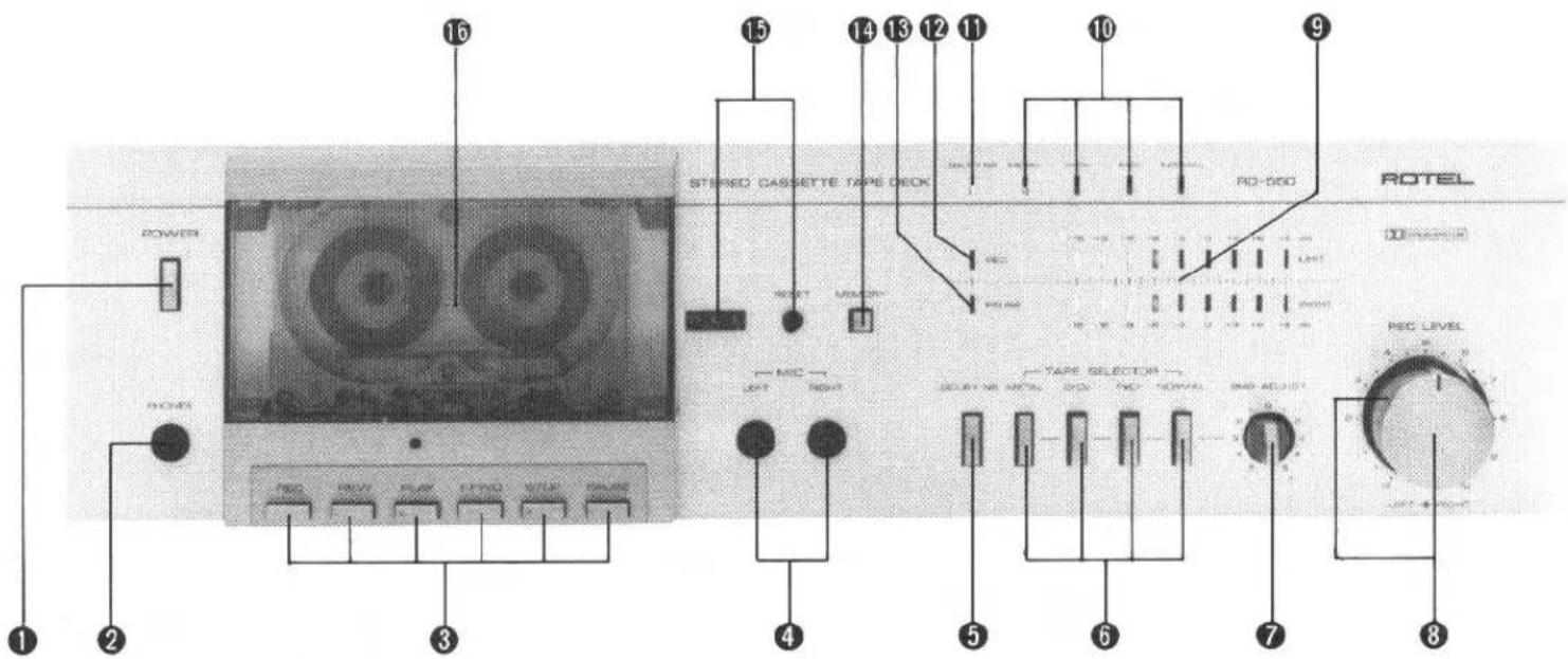
SWITCHES AND CONTROLS
(1) Power Button
Depressed once, this button turns on power in the tape deck. Pressed a second time, the button is released and the unit is turned off.
(2) Headphone Jack
For headphone listening from the deck, the headset is plugged into this jack. Before beginning, make sure the volume control of your amplifier is set to minimum.
(3) Cassette Mechanism Controls
REC Button
To record, depress this button. The deck is now in the recording mode, and the tape should be winding.
REW Button
For rapid tape rewind, depress this button.
PLAY Button
Depress this button to start the cassette for playback of recorded tape.
F.FWD Button
Depress this button to advance the tape rapidly forward.
STOP Button
Depress this button to stop the tape in any mode: record, playback, rewind or fast-forward. This button will release any transport button currently engaged.
PAUSE Button
Depress this button to stop the tape temporarily during recording or playback. To restart the tape, press this button a second time and return to the interrupted mode.
(4) Microphone Jacks
When making live recording with stereo microphones, insert the microphone plugs into these jacks. Make sure the right-hand microphone is connected to the right channel jack, and the left-hand microphone to the left channel jack. Be sure to unplug the microphones when recording from other sources.
(5) Dolby NR Switch
Depress this button to switch in the built-in Dolby NR circuit provided for high-frequency range noise reduction when you wish to record or play back through Dolby NR circuit.
(6) Tape Selector
Used to select the appropriate recording bias and playback equalization, according to type of cassette tape used. Use the METAL button for metal tape, the CrO2 button for chromium dioxide tape, the FeCr button for ferrichrome tape, and the NORMAL button for normal tape. See "TAPE SELECTOR SETTING GUIDE" for details of various brands of cassette tapes and their proper selector positions.
(7) Bias Fine-adjust Control
This control lets you to obtain the optimum bias setting to match the property of tape being used when recording. Turn the knob towards the "+" side to increase the bias and towards "-" to decrease it. See "TAPE SELECTOR SETTING GUIDE" for details.
(8) Recording Level Control
Used to control the recording level of incoming signals, such as from a turntable, tuner, or microphones. This is a dual concentric knob which permits either separate or combined adjustment of both channels. Use the outer ring for the left channel, and the knob for the right channel.
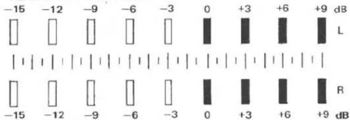
(9) Level Indicator
Gives display of recording or play-back level for both left and right channels. Each row of 9 LEDs directly shows levels from -15dB to +9dB.
(10) Tape Indicator
Tells you which button of the Tape Selector has been selected.
(11) Dolby NR Indicator
Glows when Dolby NR switch is on, indicating the unit is in Dolby NR recording or playback mode.
(12) Recording Indicator
Glows to indicate recording is in process when REC button on the cassette control section is depressed.
(13) PAUSE Indicator
Glows to indicate tape motion is temporarily stopped when PAUSE button on the cassette control section is depressed.
(14) Memory Button
This button activates the unit memory of a starting position for playback or recording. When the button is depressed, the unit memorizes the "000" position on the tape counter. When REW button is depressed, the tape keeps winding until the counter reaches "000," at which point the tape stops automatically.
(15) Tape Counter and Reset Button
The three-digit tape counter indicates the amount of tape travel. Push the reset button to set the counter to "000." This counter is convenient in finding the beginning of a specific section of the tape or checking the amount of the remaining tape on a cassette.
(16) Tape Holder
Cassette tape is loaded onto this holder.
TAPE SELECTOR SETTING GUIDE
| TAPE SELECTOR POSITION | MANUFACTURE | BRAND | BIAS ADJUST CONTROL |
| NORMAL | TDK | OD | 0 |
| AD | 0 | ||
| FUJI FILM | Range 6 | -5 | |
| SONY | AHF | 0 | |
| BHF | -5 | ||
| MAXELL | UD | -1 | |
| XLI | -1 | ||
| SCOTCH | MASTER 120 | -2 | |
| FeCr | SONY | DUAD | 0 |
| BASF | FCR | -3 | |
| CrO2 | TDK | S A | -5 |
| FUJI FILM | RANGE 4X | -5 | |
| SONY | JHF | 0 | |
| MAXELL | XL II | 0 | |
| SCOTCH | MASTER II | -5 | |
| BASF | SCR | -2 | |
| METAL | TDK | MA | 0 |
| FUJI FILM | Suqer Range | 0 | |
| SONY | METALLIC | 0 | |
| MAXELL | MX | -5 | |
| SCOTCH | METAFINE | -2 |
AUTOMATIC SHUTOFF SYSTEM
To protect the RD-550's motor and drive mechanism against unnecessary wear, an automatic shut-off device has been built into the machine. When the supply hub stops for any reason the motor and drive mechanism will automatically shutoff after a short period of time (usually about 5 seconds). The machine is also automatically shut-off at the end of tape (PLAY, REC/PLAY, FAST FORWARD and REWIND modes), disengaging all locked buttons.
Note: Since this device will not affect the electronic circuits of the machine it will still be necessary to turn off the entire unit by pushing the power switch.
CASSETE TAPES
High-performance tapes ranging from normal to metal types are suitable for this component. In addition, tape, tension and capstan tolerance for this unit have been carefully adjusted to the specific tape thickness of C30, C60 and C90 cassettes. For this reason, the use of C120 cassettes is not recommended. As cleanness and precision are necessary for accurate sound reproduction, cassettes should always be handled with care, and kept away from dust and magnetic influences which might cause sound distortion.
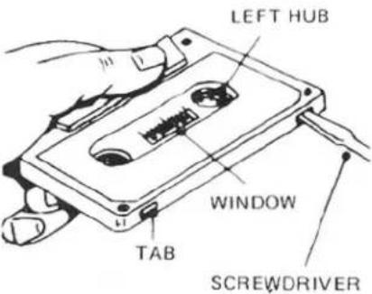
Cassette tapes are provided with a safety feature which prevents against accidental erasure of previously recorded material. This feature consists of two small tabs located on both sides at the rear of the cassette housing. After a recording has been made, these tabs are removed, leaving two small, square openings which prevent further recording on that tape. (You will notice that these tabs are absent on any pre-recorded tapes you may have.) If you wish to guard against erasure on a recording you have made on a blank cassette, it is necessary to remove one or both of these tabs as follows:
-
If both sides have been recorded, insert a thin bladed screwdriver in the opening around each tab and gently pry the tab off. Be sure the tab falls free from the cassette.
-
If one side only has been recorded, place the cassette on a table just as it has been removed from the recorder, with the side recorded facing up and the exposed tape area facing you. You should then remove the tab in the left-hand corner to prevent erasure of that side of the tape.
If you later wish to record over a previously recorded tape, simply place a piece of adhesive tape over the opening. This will allow you to make a new recording. Removal of the tape after recording will again insure against accidental erasure.
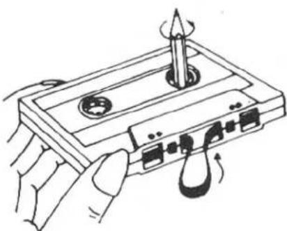
The cassette tape, when wound loosely on either hub, is likely to jam around the capstan and pinch roller during recording or playback. Therefore, if the tape is loose, insert a pencil into the more tightly wound hub, and turn it with the pencil until the slack is taken up. Always be sure to check that the tape is wound tightly before inserting a cassette in your deck.
BEFORE RECORDING OR PLAYBACK
- Be certain that power connection and connection with amplifies are properly made.
- When recording, be sure the safety tabs on the cassette tape are not removed.
- Be sure to unplug the microphones from the deck when recording from other sources.
- To load the cassette tape, hold it by the sides and fit the top under the upper projecting section of the cassette holder. Then gently push in the bottom portion of the cassette tape so that the two catches on the lower holder secure the cassette snugly. To unload the cassette, hold it by the sides, and first detach it from the lower holder by pulling gently. Then detach from the upper holder.
- Be sure to attach the protection cover to the tape holder when the unit is not in use.
RECORDING
- When recording with microphones, the microphone plugs must be inserted properly into the left and right microphone jacks.
-
When recording from line sources, choose the desired program (tuner, turntable, etc.) on your amplifier.
-
When you wish to record using Dolby NR circuit, set the Dolby NR switch to ON position.
-
Set the Tape Selector according to type of tape used.*
- Turn on the deck Power switch.
-
Press REC and PAUSE buttons simultaneously.
-
Adjust the recording level for left and right channels with Recording Level control so that the level indicator reading does not exceed 0dB position too frequently. (See figure.)
PEAK LEVEL INDICATOR
- After adjusting recording level, press the PAUSE button again to put the unit into recording mode and to start the tape.
- Be careful to watch the level indication during recording as well. PAUSE button may be used to halt recording temporarily.
- Press STOP button when recording is finished. When the end of the tape is reached, the REC button will automatically disengage and the tape stops.
* When setting the Tape Selector, also set the Bias Fine-adjust control to the appropriate position. See "TAPE SELECTOR SETTING GUIDE" for optimal setting.
PLAYBACK
- When using Dolbyized tapes, set the Dolby NR switch to ON. For non-Dolbyized tapes, set the switch to OFF.
- Set the Tape Selector to match the type of tape used.
- Turn on the power switch on your amplifier, keeping its volume control set to minimum. When using headphones connected to the tape deck, the amplifier is not necessary.
- Turn on the Power switch on the deck.
- Depress PLAY button and play-back will begin.
- To momentarily halt playback, depress the PAUSE button. When you wish to end playback, press the STOP button. When the tape comes to an end, it stops automatically and playback mode is disengaged.
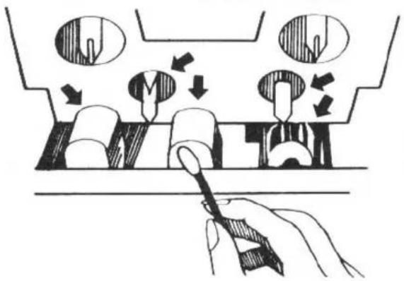
HEAD CLEANING
The most frequent cause of failure to record in one or both channels, or of weak, distorted sound, is dirty tape heads and capstan. So, be sure to clean the heads, capstan, pinch roller and tape guides as often as possible using a "Q" tip dipped in ordinary rubbing alcohol or commercial liquid tape head cleaner. Thoroughly wipe the surface of the heads, cpastan, roller and tape guide.
HEAD DEMAGNETIZING
The tape heads, capstan and tape guides gradually become magnetized with use, which will eventually affect the sound quality of your tapes. Demagnetizing should follow cleaning, but need not take place as often as cleaning, once after every 20 to 30 hours of use should suffice.
A demagnetizer may be purchased at a moderate cost from any dealer carrying tape recording accessories. Follow the instruction supplied with the demagnetizer.
Caution: Push the power switch off before you attempt demagnetizing.
SPECIFICATIONS
Heads. . . . . . . . . . . . . . . . . . . . . . . . . . . . . . . . . . . . . . . . . . . . . . . . . . . . . . . . . . . . . . . . . . . . . Low-interference shield-type ferrite/permalloy combination (ERASE)
Track....4-track/2-channel
Tape Speed . . . . . . . . . . . . . . . . . . . . . . . . . . . . . . . . . . . . . . . . . . . . 4.8cm/sec.
Motor. . Electronically controlled DC motor
Wow and Flutter . . . . . . . . . . . . . . . . . 0.1% (DIN)
0.05% (WRMS)
Distortion (REC/PB, 400Hz) ...0.6% (METAL)
Frequency Response
Normal, LH . . . . . . . . . . . . . . . . 30 to 14,000Hz ±3dB
Chromium....30 to 15,000Hz ±3dB
FeCr . . . . . . . . . . . . . . . . . . . . . . . . . . . . . . . . . . . 30 to 16,000Hz ±3dB
Metal . . . . . . . . . . . . . . . . . . . . . . . . . . . . . . . . . . . . . . . . 30 to 17,000Hz ±3dB
Signal-to-Noise Ratio.....Dolby NR IN: 65dB (Chromium) Dolby NR OUT: 55dB
Input Sensitivity/Impedance
MIC. . . . . . . . . . . . . . . . . . . . . . . . . . . . . . . . . . . . . 0.3mV/10 kohms
LINE....25mV/47 kohms
Output Level/Impedance
LINE . . . . . . . . . . . . . . . . . . . . . . . . . . . . . . . . . . . . . . . . . . . . . . . . . 580mV/1 kohms
Fast Wind Time (C-60)....80 seconds
| Tape Selector | BIAS | EQUALIZER | BIAS ADJ. |
| Normal, LH | 100% | 120μS | ±10% |
| Chromium | 150% | 70μS | ±10% |
| FeCr | 110% | 70μS | ±10% |
| Metal | 200% | 70μS | ±10% |
MISCELLANEOUS
Power Requirement....120V/60Hz, 220V/60Hz, 240V/60Hz 120, 220, 240V/50-60Hz
Power Consumption .....11 watts
Dimensions (overall) .....W 430mm/16-15/16"
H 115mm/4-17/32"
D 294mm/11-9/16"
Weight (net) .5.2kg/11.44 lbs.
Note: Specifications and design subject to modification without prior notice.
Dolby and the double-D symbol are trademarks of Dolby Laboratories.
Noise reduction system manufactured under license from Dolby Laboratories.
HEAD CLEANING
- OWNER'S MANUAL
- ROTEL®
- RD-55O
- INTRODUCTION
- POWER SUPPLY CONNECTION
- INSTALLATION
- CONNECTION TO INTEGRATED AMPLIFIER
- EXCLUSIVE NOTE FOR U.K
- SWITCHES AND CONTROLS
- POWER BUTTON
- HEADPHONE JACK
- CASSETTE MECHANISM CONTROLS
- REC BUTTON
- REW BUTTON
- PLAY BUTTON
- F.FWD BUTTON
- STOP BUTTON
- PAUSE BUTTON
- MICROPHONE JACKS
- DOLBY NR SWITCH
- TAPE SELECTOR
- BIAS FINE-ADJUST CONTROL
- RECORDING LEVEL CONTROL
- LEVEL INDICATOR
- TAPE INDICATOR
- DOLBY NR INDICATOR
- RECORDING INDICATOR
- PAUSE INDICATOR
- MEMORY BUTTON
- TAPE COUNTER AND RESET BUTTON
- TAPE HOLDER
- AUTOMATIC SHUTOFF SYSTEM
- CASSETE TAPES
- BEFORE RECORDING OR PLAYBACK
- RECORDING
- PLAYBACK
- HEAD CLEANING
- HEAD DEMAGNETIZING
- SPECIFICATIONS
Mærke : ROTEL
Model : RD-550
Kategori : Kassetteafspiller