
VT-61060 - Bộ sạc pin V-TAC - Hướng dẫn sử dụng miễn phí
Tìm hướng dẫn sử dụng thiết bị miễn phí VT-61060 V-TAC ở định dạng PDF.

Câu hỏi của người dùng về VT-61060 V-TAC
0 câu hỏi về thiết bị này. Trả lời những câu bạn biết hoặc đặt câu hỏi riêng.
Đặt câu hỏi mới về thiết bị này
Tải xuống hướng dẫn cho thiết bị của bạn Bộ sạc pin ở định dạng PDF miễn phí! Tìm hướng dẫn của bạn VT-61060 - V-TAC và lấy lại thiết bị điện tử của bạn. Trên trang này được đăng tải tất cả các tài liệu cần thiết để sử dụng thiết bị của bạn. VT-61060 thương hiệu V-TAC.
HƯỚNG DẪN NGƯỜI DÙNG VT-61060 V-TAC
V-TAC
Meaningful Innovation.
INSTRUCTION MANUAL
50 - 60Kw GRID TIED SOLAR INVERTER
natural_image
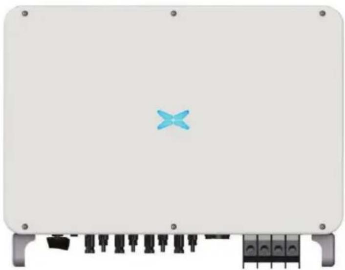
Front view of a white electronic device with a blue 'X' symbol on top and black connectors at the bottom (no text or labels visible)| SKU | MODEL |
| 11521 | VT-6607150 |
| 11631 | VT-61060 |
Preface
The manual is intended to provide detailed information of product information, installation, application, trouble shooting, precautions and maintenance of iMars series grid-tied solar inverters manual does not contain all the information of photovoltaic system. Please read this manual c follow all safety precautions seriously before any moving, installation, operation and maintenance ensure correct use and high performance are the inverter.
The use of the iMars series grid-tied solar inverters must comply with local laws and reg grid-tied power generation.
The manual needs to be kept well and be available at all times.
All rights reserved. The contents in this document are subject to change without notice.
There might be some deviations on actual inverter and data due to product updating, please the actual product.
Content
Preface ....i
1. Safety precautions .... 1
1.1 Warning marks ....1
1.2 Safety guidance .... 1
1.2.1 Transport and installation .... 3
1.2.2 Grid-connected operation 3
1.2.3 Maintenance and inspection....4
1.2.4 Waste disposal .... 4
2 Product overview 5
2.1 PV grid-connected power generation system 5
2.1.1 Supported grid connection structure ....5
2.2 Product appearance....6
2.3 Nameplate description....7
2.4 Product model....8
2.5 Outline dimension and weight 8
2.6 The LED light panel....9
2.6.1 LED light panel 9
2.6.2 LCD operation panel....10
2.7 Bottom of the chassis....11
3 Inverter storage 12
4 Installation....13
4.1 Unpacking confirmation .... 13
4.2 Prepare before tailration....15
4.2.1 Installation tool....15
4.2.2 Installation environment....15
4.3 Space requirements....16
4.4 Mounting board size....17
4.5 Wall installation 17
4.6 Install the inverter 18
5 Electrical connection....20
5.1 Overview of electrical connections....20
5.2 Connect the protective ground wire ....20
5.3 Connection of photovoltaic string 21
5.4 Three-phase inverter grid access....23
5.4.1 Connection terminal grid access....23
5.4.2 Parallel requirements for multiple inverters....24
5.4.3 Grid voltage requirements 24
6 Running 25
6.1 Inspection before running 25
6.2 Inverter grid-connected running....25
6.3 Inverter stop....26
6.4 Daily maintenance and inspection 26
6.4.1 Periodic maintenance on the inverter 26
6.4.2 Maintenance guidance 27
7 Troubleshooting 29
8 Contact information....33
9 Appendix 34
1. Safety precautions
iMars series grid-tied solar inverters are designed and tested strictly in accordance with rel international safety standards. As an electrical and electronic device, all relevant safety regulation be strictly complied during installation, operation, and maintenance. Incorrect use or misuse may result in:
●Injury to the life and personal safety of the operator or other people.
●Damage to the inverter or other property belonging operator or other people.
In order to avoid personal injury, damage to the inverter or other devices, please strictly following safety precautions.
This chapter mainly describes various warning symbols in operation manual and provides safe instructions for the installation, operation, maintenance and use of the iMars series grid-tied sol-inverters.
1.1 Warning marks
Warning marks is alerting users to conditions which may cause serious physical injury or damage to the device. They also tell users how to prevent the dangers. The warning marks operation manual are shown below:
| Mark Name | Instruction | Abbreviation | |
 Danger Danger | Danger | Serious physical injury or even death n occur if not follow relevant requirements. |  |
 Warning Warning | Warning | Physical injury or damage to the device may occur if not follow relevant requirements. |  |
 Forbid Forbid | Electrostatic sensitive | Damage may occur if relevant requirements are not followed. |  |
 Hot Hot | High temperature | Do not touch the base of the inverter will become hot. |  |
| Note | Note | The procedures taken for ensuring proper operation. | Note |
1.2 Safety guidance
 | ● After receiving this product, first please confirm the product package any question, please contact the logistic company or local distributor ● The installation and operation of PV inverter must be carried out b |
| technicians who have received professional trainings and thoroughly familiar with all the contents in this manual and the safety requirements of the electrical system.Do not carry out cable connection/disconnection, cover open for inspection and unit replacement operations on the inverter when power is connected. Before wiring and inspection, users must confirm the breakers on DC and AC side are disconnected and wait for at le | |
 | ● Ensure there is no strong electromagnetic interference caused by other electronic or electrical devices around the installation site.Do not refit the inverter unless authorized.All the electrical installation must conform to local and national electrical standards. |
 | ● Do not touch the housing of the inverter or the radiator to avoid may become hot during operation |
 | ● Must be reliably grounded before operation. |
 | ● Do not open the surface cover of the inverter unless authorized. The electronic components inside the inverter are electrostatic sensitive. Do take proper anti-electrostatic measures during authorized operation. |
 | ● Grounding mark. The inverter must be reliably grounded. |
 >min >min | ● Discharging mark. Ensure that DC and AC side circuit breakers have been disconnected and wait at least 5 minutes before wiring and checking. |
| Note: Technical personnel who can perform installation, wiring, commissioning, maintenance, troubleshooting and replacement of the iMars series grid-tied solar inverters must meet the following requirements: | |
| ● Operators need professional training.● Operators must read this manual completely and master the related safety precautions.● Operators need to be familiar with the relevant safety regulations for electrical systems.● Operators need to be fully familiar with the composition and operating principle of the entire grid-tied photovoltaic power generation system and related standards of the countries/regions in which the project is located.● Operators must wear personal protective equipment. | |
1.2.1 Transport and installation
 | ● During storage or transport, ensure the inverter package and the chassis is inta dry and clean.● The movement and installation of the inverter require at least two its heavy weight.● Select proper tools for movement and installation to ensure the inverter can operate normally and avoid physical injury. The installation personnel must take mechanical protective measures such as wearing anti-drop shoes or working clothes to protect physical security● The inverter must be installed by professional technicians.● Do not store or install the inverter on or close to flammable and ● Do not install the inverter in the place where children and other touch● Remove the metal accessories in hands eg ring or bracelet before device installation and electrical connection to avoid electric shock.● The solar cell module exposed to the sunlight may generate dangerous voltage Users must cover solar cell with fully-lightproof materials before electrical connection● The inverter input voltage cannot exceed the max input voltage, otherwise the inverter may be damaged.● PV grid-connected inverter is not applicable to the positive or negative ground system of solar cell panel.● Ensure inverter PE is grounded properly, otherwise the inverter cannot run normally.● Ensure the inverter is installed firmly and electrical wiring is reliable. |
Note: PV grid-connected inverter is only suitable for crystalline silicon-type solar battery component.
1.2.2 Grid-connected operation
 | ● Permissions by local electric power agency must be obtained and the inverter grid-connected power generation operation must be done by professional technicians. ● All electrical connections must meet the electrical standards of the countries/regions which the project is located. ● Ensure the inverter is installed firmly and electrical wiring is reliable before operating on the inverter. ● Do not open the inverter when it is running or connecting power |
1.2.3 Maintenance and inspection

● The maintenance, inspection and repair of the inverter must be done by well trail and qualified professional technicians.
- Contact distributor or manufacture for inverter repairing.
- In order to avoid irrelevant personnel entering the maintenance area during maintenance, temporary warning labels must be placed to warn non-professionals to enter or please isolate with fences.
- Before carrying out any maintenance operations, users must disconnect the breaker grid side, then disconnect the breaker connected to the PV module and wait minutes until the internal parts of the inverter are fully discharged.
● The internal of inverter are mostly electrostatic-sensitive circuits and parts, users m follow electrostatic protection rules and take anti-electrostatic measures.
- Do not use components provided by other companies when repairing the inverter
- The inverter can be started again for grid-connected power generation only after confirming there is no fault that may impact performance safety of the inverter.
- Do not get close to or touch the grid or any metal conductive parts in the generation system during operation, otherwise electric shock or fire may occur. Ta note of any safety marks and instructions such as “Danger, electric shock risk”.
1.2.4 Waste disposal
- Do not dispose of the inverter together with household waste. The user has the responsibility and obligation to send it to the designated organization for recycling disposal.
2 Product overview
This chapter mainly introduces the appearance, package accessories, nameplate, technical parameters of the grid-connected inverter.
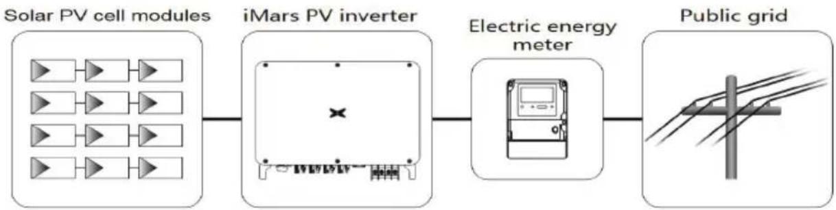
2.1 PV grid-connected power generation system
PV grid-connected power generation system is comprised of solar battery component, grid-connected inverter, power energy gauging device and public grid.
flowchart
graph LR
    A["Solar PV cell modules"] --> B["iMars PV inverter"]
    B --> C["Electric energy meter"]
    C --> D["Public grid"]
Fig 2.1 Application of PV grid-connected inverter
The PV grid-connected inverter is the core part of solar PV grid-connected power generation. The sunlight can be converted through PV panel to DC power, which further converted by grinverter to the sine AC current with the same frequency and phase position as the public gfeedback the AC power to the grid.

- It is recommended that the PV array to be installed conforms to standards. IEC 61730
2.1.1 Supported grid connection structure
iMars series grid-tied solar inverters support TN-S, TN-C, TN-C-S, TT and IT grid connected to the TT connection, the N-to-PE voltage should be less than 30V.
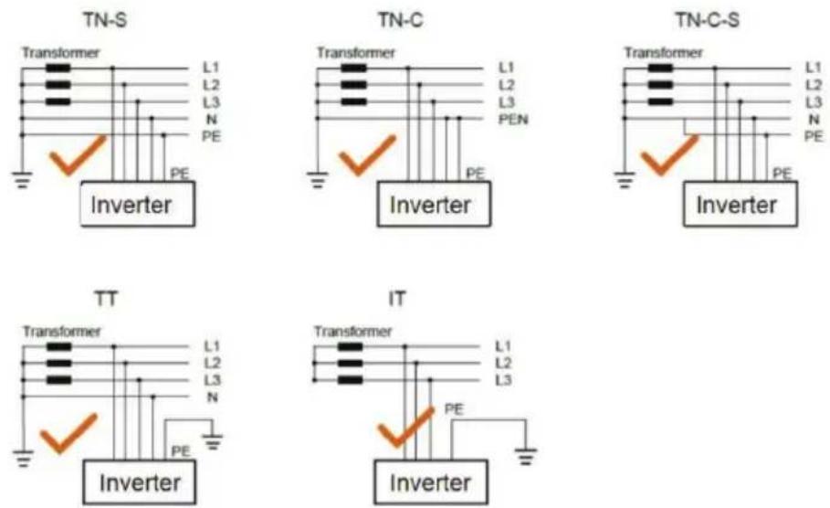
Fig 2.2 Type of grid
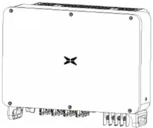
2.2 Product appearance
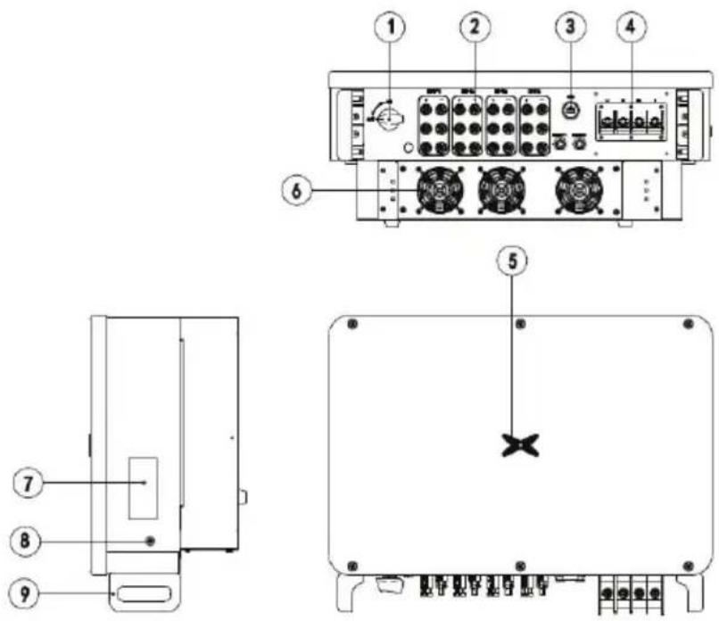
Figure 2.3 Appearance of the three-phase PV inverter
Table 2-1 Description of key exterior components of three-phase PV inverters
| Serial number | Name Description | |
| 1 | DC switch Connect DC input | |
| 2 DC input interface | Inverter DC input terminal, connected to array | |
| 3 Communication interface | RS485 communication interface and its extension port EXT | |
| 4 AC terminal | Inverter AC output port, connect to public g | |
| 5 LED pilot lamp Instructions | inverter current working condition | |
| 6 | Fan Installation components | Air inlet, for fixing the fan |
| 7 | Nameplate | Mark the inverter rating parameter |
| 8 | Ground terminals /4 | Two nos, at least one was selected for connection |
| 9 | Base handle | Two left and right for handling of inverter |
2.3 Nameplate description
Figure 2.4 shows the inverter nameplate..
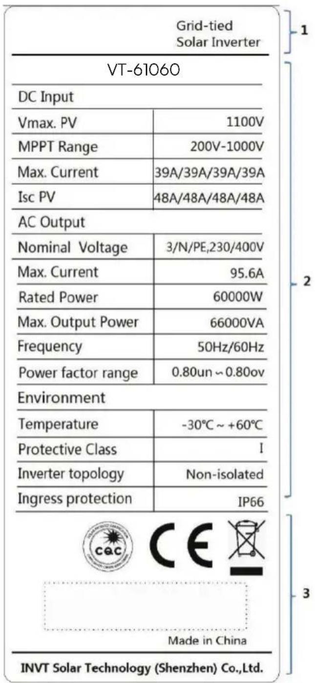
Fig 2.4 Inverter nameplate
(1) Trademarks and product types
(2) Model and important technical parameters
(3) Certification system of the inverter confirming, serial number, company name and country of origin
| Icons Instruction | |
 | ● TUV certification mark. The inverter is certified by TUV |
 | ● CE certification mark. The inverter complies with the CE directive |
 | ● CQC certification mark. The inverter passed CQC certification |
 | ● EU WEEE mark. The inverter cannot be disposed of as domestic waste |
2.4 Product model
Table 2-2 Models of three-phase PV grid-connected inverters
| Product name Model Rated output power (W) | |
| three-phase (L1、L2、L3、N、PE) | |
| Three-phase PV grid-connected inverter | XG50KTR 50000 (400Vac system) |
| Three-phase PV grid-connected inverter | XG60KTR 60000 (400Vac system) |
| Three-phase PV grid-connected inverter | XG66KTRL 66000 (480Vac system) |
| Three-phase PV grid-connected inverter | XG70KTRL 70000 (480Vac system) |
Note: Technical parameters of PV grid-connected inverter refer to the appendix.
2.5 Outline dimension and weight
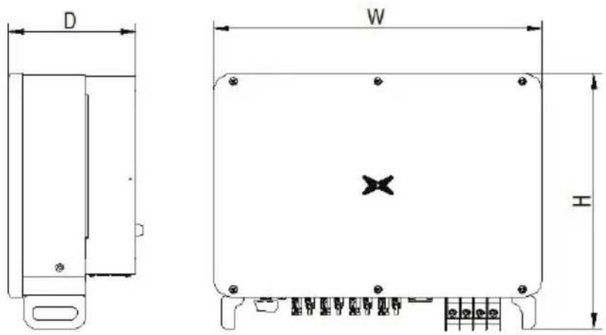
Figure 2.5 Outline dimensions of the inverter
Table 2-3 Dimensions and net weight of the inverter
| Model Height(mm) Width(mm) Depth(mm)) Net weight(kg) | ||||||
| XG50KTR 500 | 650 | 260 | 42.5 | |||
| XG60KTR 500 | 650 | 260 | 45.3 | |||
| XG70KTRL 500 | 650 | 260 | 45.3 | |||
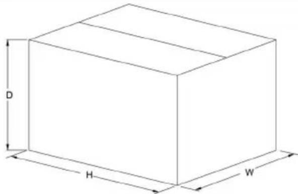
Fig 2.6 Dimension of paper package
Table 2-4 Package dimension and gross weight
| Model | Height(mm) | Width(mm) | Depth(mm) | Weight(kg) | Package material |
| XG50KTR | 785 | 640 | 385 | 47.2 | Corrugated case |
| XG60KTR | 785 | 640 | 385 | 51 | Corrugated case |
| XG70KTRL | 785 | 640 | 385 | 51 | Corrugated case |
2.6 The LED light panel
The LED indicator panel as the human-computer interaction interface, may indicate the work state of the inverter.
2.6.1 LED light panel
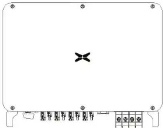
natural_image
Front view of a rectangular electronic device with a central cross symbol and surrounding circuitry (no text or labels)LED indicator status description:
 | Steady blue | Normal, grid-tied and generating power |
| Blinking blue at short interval (0.2s) | Bluetooth connected and with communication. And inverter has no error | |
| Blinking blue at long interval (2s) | DC or AC connected, inverter standby or starting (no power generation) | |
 | Steady red | Error occurs.( The inverter fail to connect to the grid) |
| Blinking red | Bluetooth connected and in communicating but inverter has error | |
| Red light off AC and | DC have been powered off. |
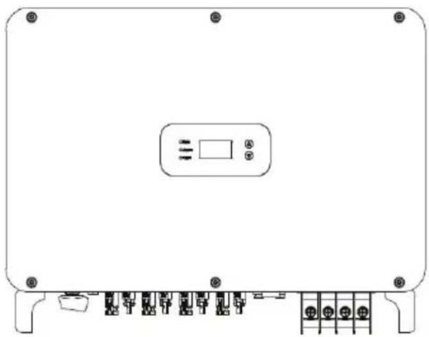
2.6.2 LCD operation panel
natural_image
Front view of a rectangular electronic device with internal components and mounting holes (no text or symbols visible)Definition of LCD operation panel:
| 1 "Run", running status, shows green light | 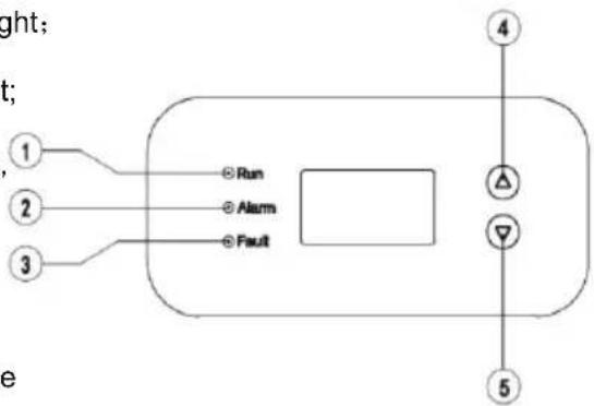 |
| 2 "Alarm", fault alert, shows yellow light | |
| 3 "Fault", the PV string is disconnected shows red light; | |
| 4 Select upwards, short press to move upwards, long press to confirm; | |
| 5 Select downward, short press to mov down, long press to return. |
LED light display status description:
| Indicator light | Instruction | State Description | |
| Run | Grid-connected indicator light | Green light on connected | to grid |
| Green light off Not connected to grid | |||
| Green light flashes 0.5s On, 0.5s Off) | The inverter is in maintenance status | ||
| Alarm | Alarm indicator | Yellow light The inverter is in fault state | |
| Yellow light flashes slowly 1s On, 4S Off | The Inverter is in alarm state | ||
| Yellow light flashes (0.5s 0.5s off) | the inverter is under maintenance | ||
| Fault | The PV connection indicator light | Red light on | The power-on indicator light indicates that at least one of the photovoltaic strings is connected normally and the input voltage is ≥200V |
| Red light off | The inverter is disconnected from all PV strings, or the DC input voltage of all MPPT circuits is less than 200V | ||
2.7 Bottom of the chassis
XG40-70KTR is equipped with a DC switch, which connects or disconnects all PV inputs.
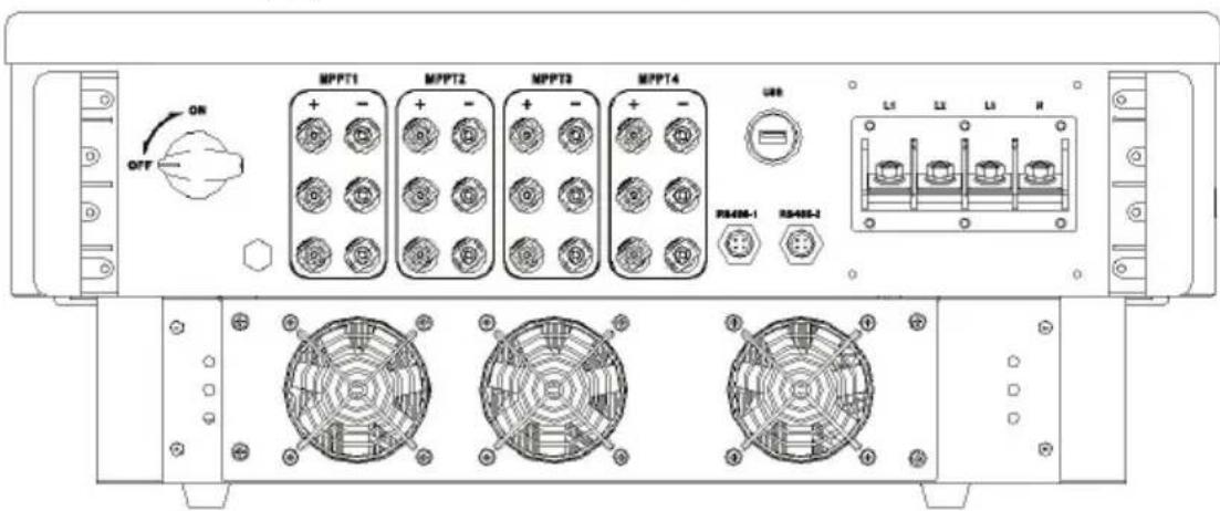
XG50KTR Bottom view
3 Inverter storage
If the inverter is not put into use immediately, the storage of inverter should meet the f requirements:
- Do not remove the inverter outer package.
- The inverter needs to be stored in a clean and dry place, and to prevent the erosion of dust and moisture.
- The storage temperature should be kept at -30^ +70^ , and the relative humidity should be kept at 5% RH 95% RH .
- If multiple inverters to be stacked, it is recommended to place them original stacking layer number at the time of delivery. When stacking, please place the inverter carefully to personal injury or equipment damage caused by equipment tipping.
- Avoid chemical corrosive substances, otherwise it may corrode the inverter.
- During storage, regular inspections are required. If insect bites or packaging damage are found, the packaging materials must be replaced in time. After long-term storage, the inverter needs to inspected rad tested by professionals before it can be put into use.
4 Installation
This chapter introduces the installation of the inverter and the connection of the inverter to power generation system. Connecting inverters to PV power generation systems mainly involves PV strings and public grids connect to the inverter.
Please read this chapter carefully before installation, and ensure that all installation condition met by professional technicians to complete the inverter installation.
4.1 Unpacking confirmation
The inverter has been thoroughly tested and rigorously checked before delivery, but damage still occur during transportation. Before unpacking, check carefully whether the product information order is consistent with that on the nameplate of the package box and whether the product intact. If any damage is detected, please contact the shipping company or the supplier directly also provide photos of the damage to get our fastest and best
When the inverter is left unused, please put it in the original packing box and take meat prevent moisture and dust.
Take out the inverter after unpacking, please check the following items:
(1) Confirm that the inverter host is complete and not damaged;
(2) Confirm that there are manuals, interface accessories and installation accessories in the box;
(3) Confirm that there is no damage or shortage in the delivery content in the packing
(4) Check whether the order is consistent with the product information on the nameplate of inverter host;
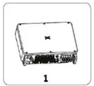
(5) The standard delivery list is as follows.
Standard deliverables of three-phase inverter:
natural_image
Line drawing of a rectangular electronic device with ports and a central label (no readable text or symbols)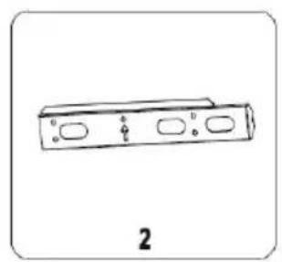
natural_image
Simple line drawing of a rectangular object with three oval cutouts and small protrusions, labeled '2' at bottom (no text or symbols on the object itself)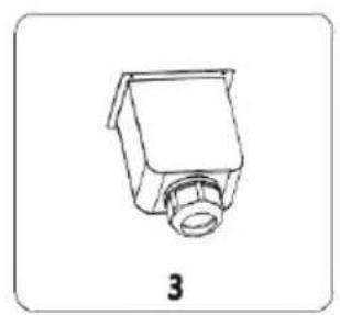
natural_image
Simple line drawing of a mechanical component with a flanged base and central hub (no text or symbols)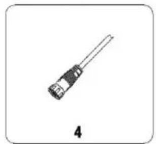
natural_image
Simple line drawing of a cylindrical connector with a black cap and lead, labeled '4' below (no text or symbols on the component itself)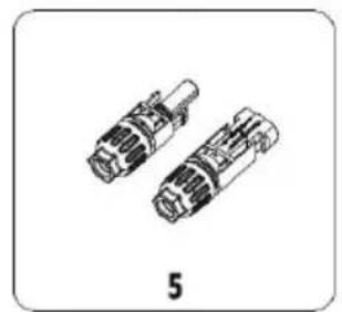
natural_image
Two identical mechanical connectors shown in line drawing style, labeled '5' below (no text or symbols on the connectors themselves)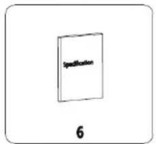
natural_image
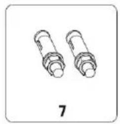
Two cylindrical mechanical components with flanges, labeled '7' below (no text or symbols on the parts themselves)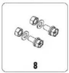
natural_image
Illustration of three mechanical fasteners with hexagonal end caps, labeled '8' below (no text or symbols on the parts themselves)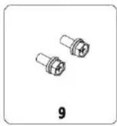
natural_image
Two cylindrical mechanical components with flanged ends, labeled '9' below (no text or symbols on the components themselves)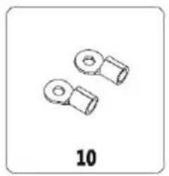
natural_image
Two identical mechanical components with circular ends, labeled '10' below (no text or symbols on the parts themselves)Fig4.1 Delivery content of three-phase inverter 50-70kW
Table 4-1 delivery contents of three-phase inverter
| Number | Name Quantity | |
| 1 Inverter 1 | ||
| 2 Mounting bracket 1 | ||
| 3 AC | output waterproof cover 1 | |
| 4 485 | communication cable 1 | |
| 5 | DC connector (pair) | 12 |
| 6 | File | 1 |
| 7 | Expansion bolt M8*60 | 5 |
| 8 | M8 combination bolt | 5 |
| 9 | M4 combination screw | 1 |
| 10 | AC terminal | 5 |
Please check the above carefully. If you have any questions, please contact the supplier
4.2 Prepare before installation
4.2.1 Installation tool
Table 4-2 List of installation tools
| Number | Installation tools instruction | |
| 1 Marker pen Mark the mounting holes | ||
| 2 Electric drill Drill holes in the bracket or wall | ||
| 3 Hand hammer Knock the expansion bolt | ||
| 4 Adjustable wrench For fixed mounting bracket | ||
| 5 | Hexagon screwdriver | For locking anti-theft screws and for disassembling and disassembling AC junction box |
| 6 | "Flat" or "Cross" screwdriver | For AC wiring |
| 7 | Meg ohmmeter | Measure insulation performance and impedance to ground |
| 8 Multi-meter Detect circuit and measure AC and DC voltage | ||
| 9 | Electric soldering iron | Welding communication cable |
| 10 | Wire crimper | Crimp DC terminal |
| 11 | Hydraulic clamp | Crimp ring terminal for AC wiring |
4.2.2 Installation environment
(1) The inverter can be installed in indoor and outdoor environment.
(2) During the operation of the inverter, the temperature of the chassis and heat sink will high. Please do not install the inverter in the easily touched position.
(3) Do not install inverters in areas where flammable and explosive materials are stored.
(4) The inverter shall be installed in a well-ventilated environment to ensure inverter heat
(5) It is recommended to choose the installation site with shelter or build
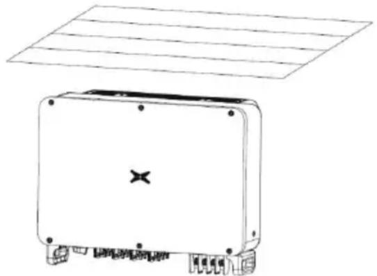
natural_image
Line drawing of a rectangular electronic device with mounting base and grid top (no text or symbols)Fig 4.2 Sunshade
(6) The installation environment temperature is - 25 °C \~ 60 °C;
(7) The installation site should be far away from the electronic equipment with strong electromagnetic interference;
(8) The installation site should be fixed and solid object surface, such as wall, metal sup
(9) The installation position shall ensure the reliable grounding of the inverter, and the gross metal conductor material shall be consistent with the reserved groundingl metathemateria inverter.
4.3 Space requirements
(1) The height of installation position shall ensure that the line of sight and LED display the same horizontal plane, so as to check the inverter status conveniently.
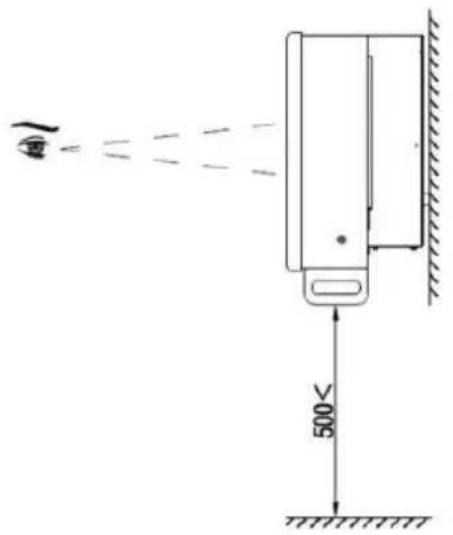
Fig 4.3 Optimum installation height area
(2) There is enough reserved space around the installation site to facilitate the disassembly assembly of inverter and air convection. As shown in Fig 4.3.
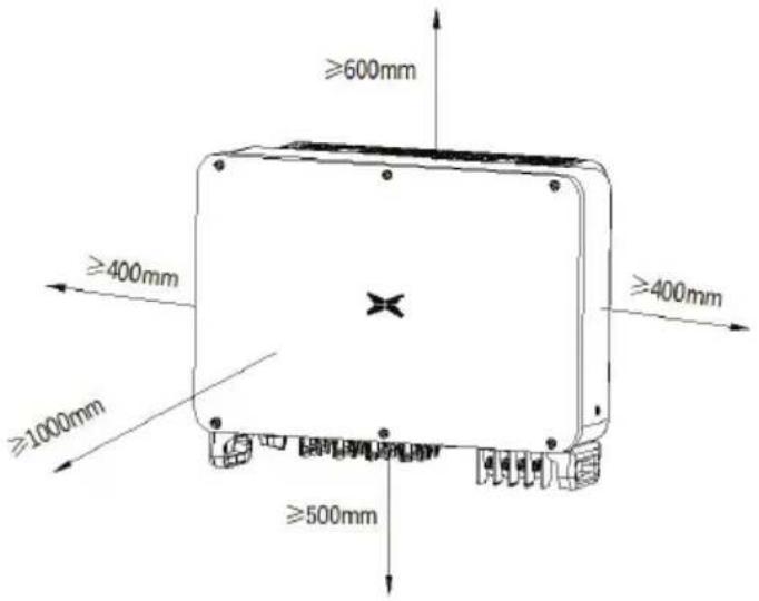
Fig 4.4 Installation spacing of inverter
(3) When installing multiple inverters, a certain distance shall be reserved between the inverter shown in Figure 4.4. At the same time, sufficient distance shall be reserved between the upper parts of the inverter to ensure good heat dissipation.
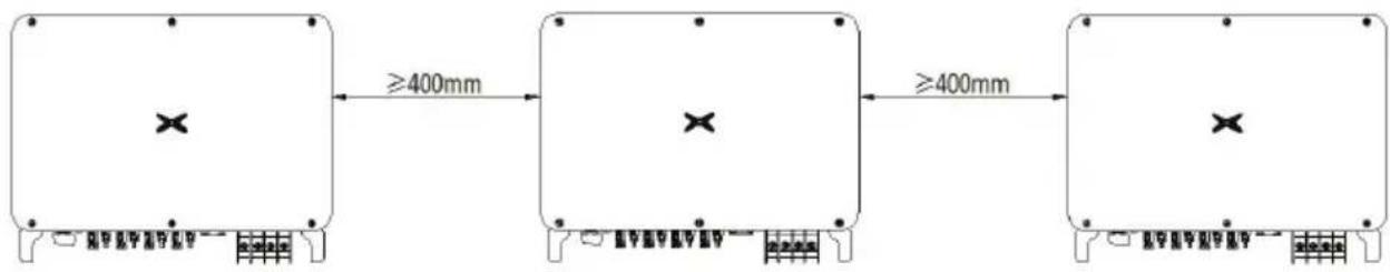
flowchart
graph LR
    A["Step 1: X marks"] -->|≥400mm| B["Step 2: X marks"]
    B -->|≥400mm| C["Step 3: X marks"]
Fig 4.5 Size requirements for side-by-side installation
(4) The installation surface should be perpendicular to the horizontal line, as shown in Fig. Please install the inverter vertically or backward ≤ 15^ to facilitate the heat dissipation of the I not tilt the inverter forward, horizontally, upside down, leaning too far, or tilting to the side.
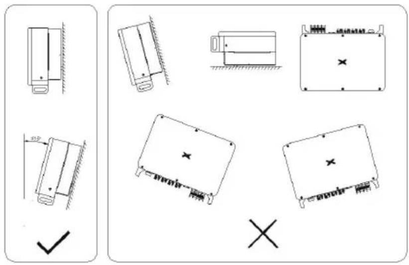
Fig 4.6 Installation position of inverter
4.4 Mounting board size
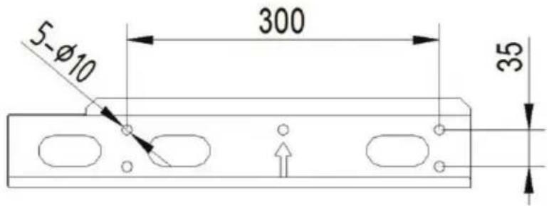
Fig 4.7 Dimensions of the mounting plate
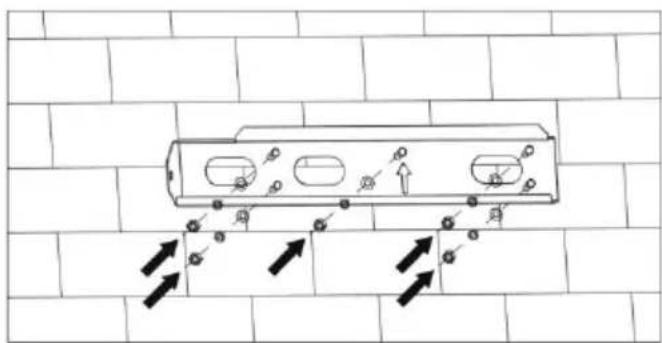
4.5 Wall installation
Step 1: Place the hanging board on the wall mounting point, use a level to adjust the angle, and mark with a marker.
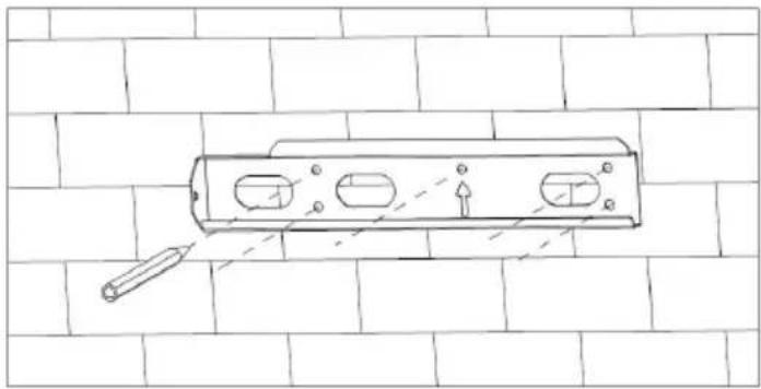
natural_image
Technical line drawing of a cylindrical mechanical component mounted on a brick wall, with no visible text or symbols.Step 2: Use a hammer drill to drill holes and install expansion bolts. Users need to pre-expansion bolts by themselves. It is recommended to use M8×60 stainless steel pressure explc-expansion bolts.
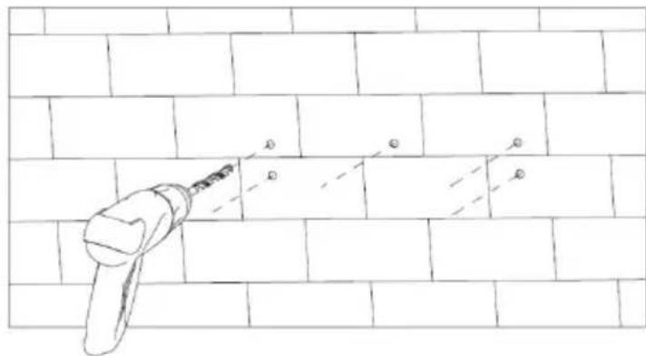
Step 3: Fix the hanging board. Clean the holes, use a rubber hammer to drive the expansion bolt into the hole, use a wrench to tighten the nut to fix the end of the bolt, then remove the and flat washer, and then fix the wall mount plate to the wall and lock it with a tightening 13N^*m 。
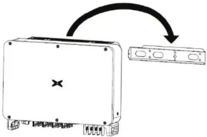
4.6 Install the inverter
Step 1: Take the inverter out of the packaging box.
Step 2: If the installation location is high, you need to lift the inverter to the hanging plate, use the lifting equipment to lift the inverter 100mm off the ground and then pause, check the tightness hoisting ring and rope. After confirming that the connection is secure, lift the inverter to the
natural_image
Line drawing of a rectangular electronic device with mounting holes and a central logo (no text or symbols)Step 3: After lifting the inverter, buckle the bracket plate on the back of the machine into the wall-mounting plate, and make sure that the machine bracket plate fits well with the groove (hanging plate.
natural_image
Diagram showing a device with an X symbol on its side, connected to a rectangular device with control buttons (no text or labels present)Step 4: Use an M4×1 2 screw to fix the inverter with the hole on the left side of the chassis and the wall mount, and the tightening torque is 2.5N*m
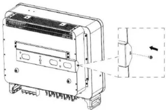
natural_image
Technical line drawing of a device housing with internal components and a close-up view showing a component (no text or symbols)5 Electrical connection
5.1 Overview of electrical connections
This section will introduce the electrical connection related content and related safety precaution detail.
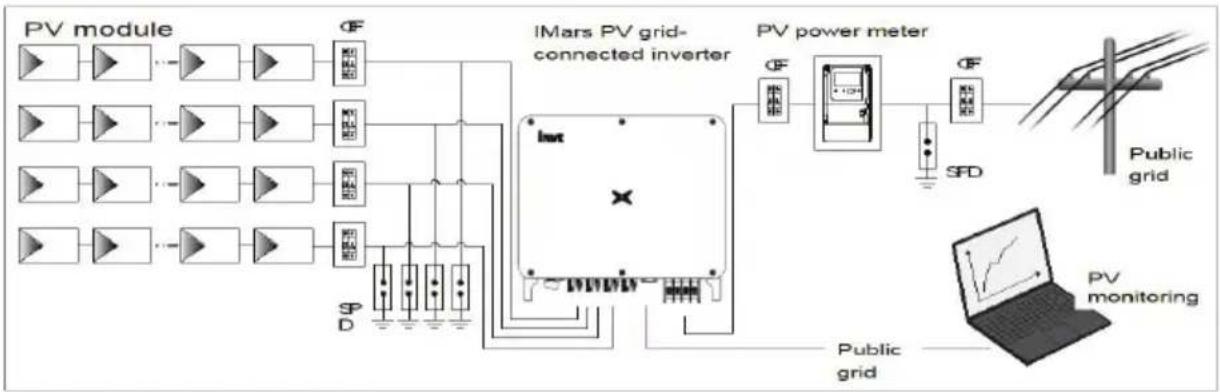
flowchart
graph TD
    A["PV module"] --> B["Φ"]
    C["IMars PV grid-connected inverter"] --> D["SP D"]
    D --> E["Inverter"]
    E --> F["PV power meter"]
    F --> G["SF D"]
    G --> H["Public grid"]
    H --> I["PV monitoring"]
    style A fill:#f9f,stroke:#333
    style C fill:#f9f,stroke:#333
    style E fill:#ccf,stroke:#333
    style F fill:#cfc,stroke:#333
    style G fill:#fcc,stroke:#333
    style H fill:#cff,stroke:#333
    style I fill:#ffc,stroke:#333
Fig 5.1 Schematic diagram of PV grid-connected system connection
 | ● Electrical connections must be completed by professional worker. Wrong operation may cause equipment damage during system operation, and even personal injury.● All electrical installations must comply with national/regional electrical safety regulations.● Ensure that all cables are installed tightly, without any damage, and meet the specified safety requirements.● It is not allowed to turn on the AC and DC circuit breakers before the inverter completes the electrical connection and check. |
| Note | ● Read this section carefully and operate strictly according to the requirements.● Pay attention to the rated voltage and current values specified in this manual, do not exceed the limit values specified in this manual. |
5.2 Connect the protective ground wire
Step 1: Crimp the OT terminal to the ground wire
Step 2: Remove the screw at the grounding position on the side of the chassis, fix the ground wire with the screw and tighten the tightening torque 7-9N·m.
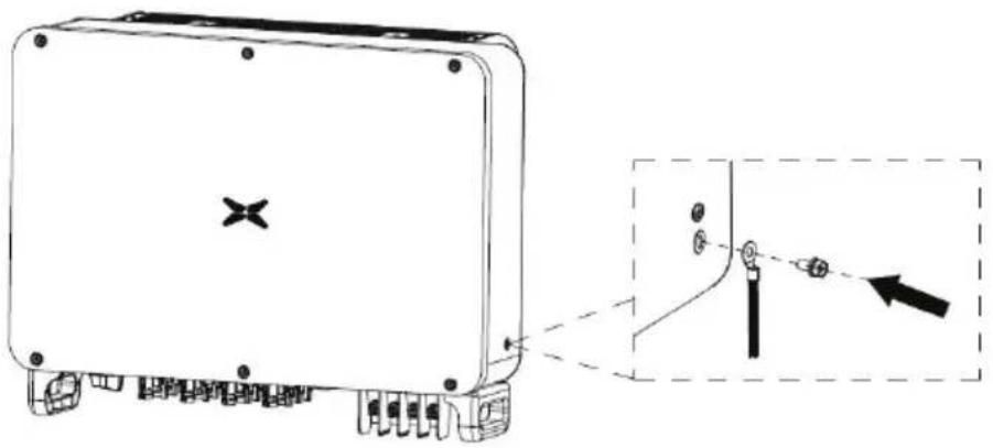
natural_image
Technical line drawing of a device with mounting holes and a close-up inset showing a mechanical component (no text or symbols)5.3 Connection of photovoltaic string
Step 1: Connect the outlet line of the PV panel to the MC4 terminal delivered by the machine
The MC4 terminal crimping method is as follows:
(1) As shown in Fig 5.2, connect the output wire of the PV string to the DC connector Loosen the fastening nut of the connector; strip off the 15mm insulation layer of the DC cal crimping pliers to press the standard metal terminal tightly. The tightening torque part that water the tail is 2.5 - 3Nm . The wiring method of the positive and negative connectors is the same. the positive and negative poles of the PV string correspond correctly to the positive and neg connectors, then connect them firmly;
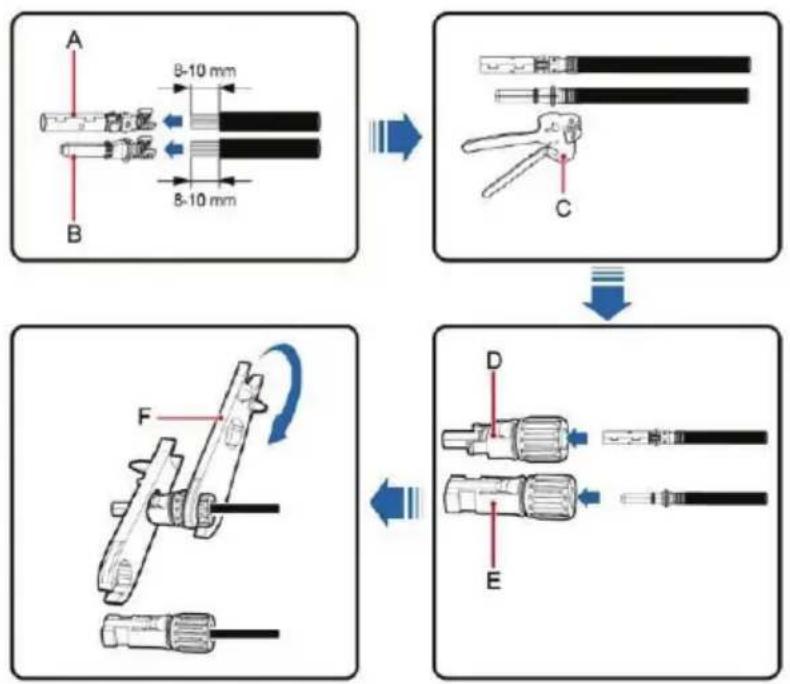
Fig 5.2 Connection between MC4 DC connector and PV string
(2) After the DC connector is connected, use a multi-meter to measure the voltage of the DC input string, verify the polarity of the DC input cable, and ensure that the voltage of each string allowable range of the inverter, as shown in Fig 5.3.
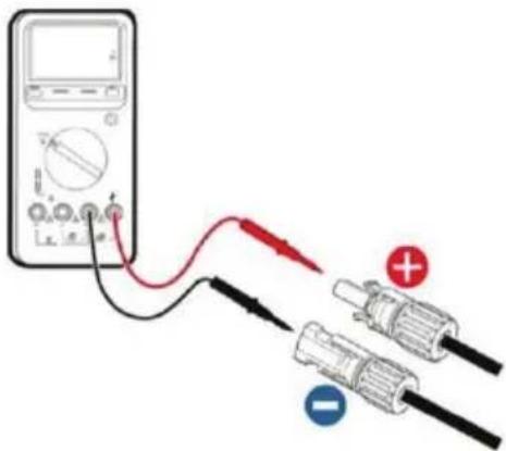
Fig 5.3 Measuring DC input voltage
 | ● The PV string connected to iMars series inverter must adopt the DC connector configured especially for the inverter, do not use other connection devices without authorization from our company, otherwise damage to the device, unstable operation or fire may occur and our company will not undertake quality assurance or assu any direct or joint liability thereof. |
Step 2: After the DC terminal is connected, it is directly connected to the MC4 terminal of the machine.
(1) Connect the positive and negative connectors of the PV strings that have been connected corresponding positions of the inverter DC interface, and confirm the tight connection, as shown 5.4;
(2) When disassembling the DC connector from the inverter, insert the tip of a slotted so into the raised hole in the middle of the connector, and ableored that they connector to withdraw.
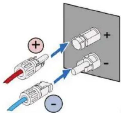
Fig 5.4 PV DC string connected to the inverter
5.4 Three-phase inverter grid access
Table 5-1 Three-phase photovoltaic inverter AC connector interface description
| Inverter ACconnector interface | Three-phase grid Remarks | |
| L1 L1 (A) | No phase sequence | |
| L2 L2 (B) | No phase sequence | |
| L3 L3 (C) | No phase sequence | |
| N N(Neutral line) | Support N-wire and non-N-wire connection | |
 | PE ground wire (grounding point on the outside of the chas | Must be connected |
5.4.1 Connection terminal grid access
(1) Connect the four wires of the three-phase public power grid L1, L2, L3 and N to the interface according to Table 5-1, and connect the grounding wire to the grounding point on the chassis, and ensure that the conductors are crimped firmly without exposure. As shown
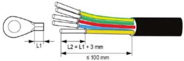
Fig 5.6 Crimp cable terminal
(2) Then tighten the L1, L2, L3, N, crimped terminals according to Fig 5.7 to a torque the PE grounding torque of the outer side of the chassis to a torque of 7 - 9N· m ; then tight Tighten the waterproof cap.
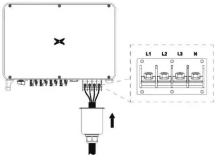
Fig 5.7 Three-phase inverter grid connection
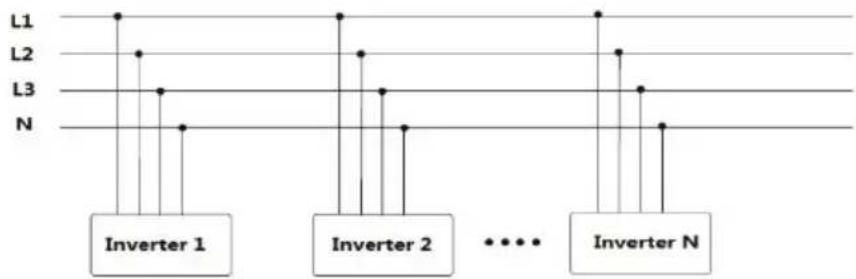
5.4.2 Parallel requirements for multiple inverters
Use multiple inverters to directly connect to the low-voltage three-phase grid solution. If the capacity of the inverters is greater than 1MVA, please contact our after-sales service personnel
flowchart
graph TD
    A["Inverter 1"] --> B["L1"]
    A --> C["L2"]
    A --> D["L3"]
    A --> E["N"]
    F["Inverter 2"] --> G["L1"]
    F --> H["L2"]
    F --> I["L3"]
    F --> J["N"]
    K["..."] --> L["..."]
    M["Inverter N"] --> N["L1"]
    M --> O["L2"]
    M --> P["L3"]
    M --> Q["N"]
Use multiple inverters to connect the low-voltage side of the medium-voltage transformer, an high-voltage side directly connects to the medium-voltage grid. If the total capacity of the inverter greater than 1MVA, please contact our service personnel. At the same time, the transformer has the total output of the inverter. Power requirements, and there is a neutral point or an external conductor.


- It is recommended to use a transformer with short-circuit impedance ≤7%
5.4.3 Grid voltage requirements
Before installing the PV inverter, you need to confirm the working voltage of the AC side product. There are two rated voltages of 400Vac and 480Vac;

- For 400Vac systems, the AC side of the inverter can be directly domestic three-phase power grid;
- For the 480Vac system, the inverter needs to be connected to the three-phase grid through a transformer, the transformer ratio is 480V/400V, and the capacity refers to the actual inverter power.
6 Running
This chapter introduces the related operations during the use of the inverter, which mainly pre-operation inspections, grid-connected operation of the inverter, inverter shutdown, and precaution for daily maintenance and repair of the inverter.
6.1 Inspection before running
The following items must be checked strictly before running the PV grid-connected inverter (including but not limited to the following items):
(1) Confirm the installation site of the inverter meet requirements of section 4.2.2 to ensure co-installation, disassemble, operation and inspection on the inverter;
(2) Confirm the mechanical installation of the inverter meet requirements of section 5.3;
(3) Confirm the electrical connection of the inverter meet the requirements of section 4.4;
(4) Confirm all the switches are in "OFF" state;
(5) Confirm the open-circuit voltage of PV module conforms to the parameter requirement DC side in appendix;
(6) Confirm the electrical safety marks on the installation site is clear enough.

- In order to ensure a safe, normal and stable operation of the PV power ge system, all the newly installed, renovated and repaired PV grid-connected power generation system and its grid-connected inverter must undergo inspection before running.
6.2 Inverter grid-connected running
Please strictly follow the steps below to turn on the inverter and complete the grid-connected operation of the inverter::
| Note | ● For the first operation of the inverter, a country must be selected to set grid-connected standards. ● Please keep the inverter powered on for at least 30 minutes, and charging of the built-in clock battery of the inverter to ensure the normal operation of the clock! |
(1) Make sure that the inspection items in Section 6.1 meet the requirements;
(2) Turn on the AC side circuit breaker of the inverter public grid;
(3) Turn on the DC switch integrated in the inverter;
(4) Turn on the switch on the DC input side of the photovoltaic string;
(5) Observe the status of the inverter's LED lights or the information displayed on the screen (refer to section 2.6 for LED status lights and LCD display information);
(6) Wait for the inverter to connect to successfully.
6.3 Inverter stop
When it is necessary to perform power failure maintenance, overhaul, and troubleshooting of inverter, please strictly follows the steps below to shut down the inverter:
(1) Disconnect the AC side circuit breaker of the inverter public grid;
(2) Disconnect the DC switch integrated in the inverter;
(3) Disconnect the line switch on the DC input side of the photovoltaic string;
(4) Wait at least 3 minutes until the internal components of discharger and the inverter shutdown operation is completed.
6.4 Daily maintenance and inspection
In the PV grid-connected system, even if the day and night change and the season cha grid-connected inverter can automatically complete grid-connected power generation, shutdown and start-up operations without human control. In order to ensure and prolong the service life of in addition to using the inverter in strict accordance with specified in this manual, it is also necessary to carry out the necessary daily maintenance and inspection of the inverter.
6.4.1 Periodic maintenance on the inverter
| Check Item | Inspection Method Maintenance Cycle | |
| Save inverter operating data | The monitoring software is used to read the data of the inverter in real time, and the data recorded by the monitoring software is regularly backed up.Save the inverter's operating data, parameters and logs recorded in the monitoring software to a file. Check the monitoring software and check the inverter parameter settings through the handheld keyboard. | Once per quarter |
| Inverter running status | Observe whether the inverter is installed firmly and whether it is damaged or deformed. To listen whether there's any abnormal sound during inverter running. When the system is connected to the grid, check various variables. Check whether the heating of the inverter shell is normal, and use a thermal imager to monitor the heating of the system. | Once per half a ye |
| Clean the inverter | Check the RH and dust around the inverter, and clean the inverter when necessary. Refer to section 6.4.2. | Once per half a ye |
| Electrical connections | Check whether the system cable connection is loose, whether the inverter wiring terminal is loose, and then tighten it according to the method specified in section 4. Check whether the damaged, especially whether the rubber skin in contact with the metal surface has cut marks. | Once per half a year cable is |
| Cooling fan maintenance and replacement | For three-phase inverter products, observe whether the air inlet and outlet are anorm check whether there are cracks in the fan blades. Listen for abnormal vibration when the fan once per half a year running. If necessary, clean the air inlet and outlet; if the fan is abnormal, it needs to be replaced in time, see section 6.4.2. | |
| Security function | Check the inverter LCD and the shutdown function of the system. Simulate stop and the stop signal communication. Check the warning labels and replace them if necessary. | check Once per half a year |
6.4.2 Maintenance guidance
Inverter cleaning
The cleaning steps are as follows:
(1) Disconnect the input and output connections.
(2) Wait ten minutes.
(3) Use a soft brush or vacuum cleaner to clean the surface of the inverter and the outlet.
(4) Repeat the operation content in section 6.1.
(5) Restart the inverter.
Fan maintenance
 | ● Stop the inverter before maintenance work, and all power inputs of the inverter must be disconnected.● Wait at least 3 minutes for the capacitors inside the inverter to fully discharge before starting maintenance work.● Only professional electricians can perform maintenance and replacement of the fan. |
Step 1: Stop the inverter and disconnect the electrical connection.
(1) Disconnect the input and output connections.
(2) Turn the DC switch to the "OFF" position.
(3) Wait ten minutes.
(4) Disconnect all electrical connections at the bottom of the inverter.
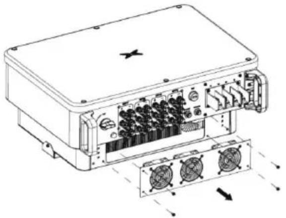
Step 2: Disconnect the fan power plug and remove the fan cover at the bottom of the chassis.
natural_image
Technical line drawing of an electronic device with internal components and fan array (no text or symbols)Step 3: Use a soft brush or vacuum cleaner to clean the fan. If the fan is damaged, follow step 4.
Step 4: If the fan is damaged, remove the damaged fan and install the good fan to it position.
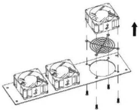
natural_image
Technical diagram of a multi-chamber electric fan assembly with mounting holes and wiring (no text or labels)Step 5: Re-install the fan tray to the inverter in the reverse order and restart the inverter.
| Note | ● Once the inverter stops due to an alarm, it is prohibited to start the inverter immediately. You should find out the cause and confirm that all faults have be eliminated before starting the inverter. The inspection should be carried out strict in accordance with the steps in section 6.1. |
7 Troubleshooting
This chapter introduces fault alarms and codes, which are used to quickly find inverter fault
Table 7-1 Inverter fault codes
| Number | Fault types | Fault main code | Fault subcode | Fault information | Display information |
| 1 | PV voltage fault | 01 | 01 | PV electricity down | 01-01 |
| 02 | PV voltage high | 01-02 | |||
| 2 | BUS voltage error | 03 | 01 | Low voltage BUS | 03-01 |
| 02 | BUS voltage high | 03-02 | |||
| 03 | BUS voltage imbalance | 03-03 | |||
| 3 | Flow failures | 05 | 01 | Inverter hardware flow | 05-01 |
| 02 | Inverter software flow | 05-02 | |||
| 03 | The BOOST hardware flow | 05-03 | |||
| 04 | The BOOST software flow | 05-04 | |||
| 4 | Thermal failure | 06 | 01 | The inverter temperature thermal | 06-01 |
| 02 | The BOOST thermal | 06-02 | |||
| 03 | The radiator thermal | 06-03 | |||
| 04 | The environmental thermal | 06-04 | |||
| 5 | Insulation detection fault | 07 01 | Insulation detection fault | 07-01 | |
| 6 | Drive failure | 08 01 | Drive failure | 08-01 | |
| 7 | Communication failure | 09 | 01 | DSP1 and ARM SCI failure | 09-01 |
| 02 | DSP2 with ARM SCI failure | 09-02 | |||
| 03 | DSP1 SPI fault | 09-03 | |||
| 04 | DSP2 SPI fault | 09-04 | |||
| 05 | SCI failure DSP1 and MCU | 09-05 | |||
| 8 | Leakage current fault | 10 01 | The static leakage current is high | 10-01 |
Three-phase Grid-tied Solar Inverter Troubleshooting
| Number | Fault types | Fault main code | Fault subcode | Fault information | Display information |
| 02 | 30 ma mutation of failure | 10-02 | |||
| 03 | 60 ma mutation of failure | 10-03 | |||
| 04 | 150 ma mutation of failure | 10-04 | |||
| 9 | Relay failure | 11 | 01 | Relay open | 11-01 |
| 02 | Relay short circuit | 11-02 | |||
| 10 | DCI fault | 14 | 01 | DCI R phase failure | 14-01 |
| 02 | DCI S phase failure | 14-02 | |||
| 03 | T the DCI fault | 14-03 | |||
| 11 | Consistency of failure | 19 | 01 | AC voltage test | 19-01 |
| 02 | BUS voltage detecting inconsistencies | 19-02 | |||
| 03 | ISO voltage detecting inconsistencies | 19-03 | |||
| 04 | PV voltage detecting inconsistencies | 19-04 | |||
| 05 | GFCI inconsistent | 19-05 | |||
| 12 | Mains voltage fault | 31 | 01 | Low mains voltage | 31-01 |
| 02 | Mains voltage high | 31-02 | |||
| 13 | Mains frequency fault | 33 | 01 | Mains frequency is low | 33-01 |
| 02 | Mains frequency is high | 33-02 | |||
| 14 | Remote shutdown | 37 01 | Remote shutdown instructions | 37-01 | |
| 15 | Leakage current self-checking of failure | 43 01 | Leakage current sensor fault | 43-01 | |
| 16 | Auxiliary power failure | 45 01 | Auxiliary power off | 45-01 |
Table 8-2 Inverter alarm codes
| Number | Alarm types | Alarm master code | alarm subcode | alarm information | Display information |
| 1 | Fan speed is low | 01 | 01 Fan1 01-01 | ||
| 02 Fan2 01-02 | |||||
| 03 Fan3 01-03 | |||||
| 04 Fan4 01-04 | |||||
| 2 | Lightning protector | 02 01 Lightning protector 02-01 | |||
| 3 | String current | 03 | 01 String 1 03-01 | ||
| 02 String 2 03-02 | |||||
| 03 String 3 03-03 | |||||
| 04 String 4 03-04 | |||||
| 05 String 5 03-05 | |||||
| 06 String 6 03-06 | |||||
| 07 String 7 03-07 | |||||
| 08 String 8 03-08 | |||||
If any problem, please contact with the supplier and provide following information:
- Model of the inverter:
- Serial No. of the inverter:
- System version:
—version 1:____;
—version 2: ____;
—MCU software version: ;
- Fault code:
- Fault description
8 Contact information
IN CASE OF ANY QUERY/ISSUE WITH THE PRODUCT
FOR MORE PRODUCTS RANGE
INQUIRY PLEASE CONTACT OUR DISTRIBUTOR OR NEAREST DEALERS.
V-TAC EUROPE LTD.
BULGARIA, PLOVDIV 4000
BUL.L.KARAVELOW 9B
support@v-tac.eu
9 Appendix
Table 9-1 Technical parameters of three-phase PV grid-connected inverter
| Model | VT-6607150VT-61060 | ||
| DC side | Maximum input power | 80000W | 96000W |
| Maximum DC voltage (V) | 1100 | 1100 | |
| Starting voltage (V) | 180 | 180 | |
| MPPT voltage range (V) | 200-1000 | 200-1000 | |
| Full load MPPT voltage range (V) | 520-850 | 520-850 | |
| Number of MPPT channels | 4 | 4 | |
| Maximum number of strings per MPPT | 3/2/3/2 | 3/3/3/3 | |
| Maximum input current per MPPT (A) | 39/26/39/26 | 39/39/39/39 | |
| Maximum short-circuit current of each MPPT (A) | 48/32/48/32 | 48/48/48/48 | |
| AC side | Rated output power (W) | 50000 | 60000 |
| Rated output voltage (Vac) | 230/400 | 230V/400 | |
| Rated output voltage frequency (Hz) | 50/60 | 50/60 | |
| Maximum output current (A) | 79.7 | 95.6 | |
| Short circuit current (A) | 150 | 160 | |
| Output voltage frequency range (Hz) | 45~55/55~65 | ||
| Power factor | -0.8~+0.8 (adjustable) | ||
| Harmonic distortion | <3% (rated power) | ||
| System | cooling method | Air-cooled | |
| Maximum efficiency | 98.70% | ||
| European efficiency | 98.60% | ||
| MPPT efficiency | 99.90% | ||
| Protection level | IP66 | ||
| Power consumption at night | <1W | ||
| Security Level | I | ||
| Overvoltage protection level | AC: III, PV: II | ||
| Inverter topology | non-isolated | ||
| Pollution level | 3 | ||
| Operating environment temperature | -30°C~+60°C (automatic derating after exceeding 45°C) | ||
| Relative humidity | 0~100% | ||
| Maximum allowable altitude (m) | ≤2000, derating is required after more than 2000m | ||
| show | LED/LCD (optional) | ||
| System language | English, Chinese, German, Dutch | ||
| communication method | RS485 (standard); Ethernet, WiFi (optional) | ||
| DC terminal | MC4 DC waterproof terminal | ||
| Noise dB(A) | ≤55 | ||
| Installation method | Wall-mounted | ||
| Protection function | Input overvoltage protection, input overcurrent protection, DC insulation monitoring, DC monitoring, ground fault current monitoring, grid monitoring, islanding protection, short circuit protection and overheating protection, etc. | ||

- V-TAC
- INSTRUCTION MANUAL
- Preface
- Content
- Preface ....i
- Safety precautions .... 1
- Product overview 5
- Inverter storage 12
- Installation....13
- Electrical connection....20
- Running 25
- Troubleshooting 29
- Safety precautions
- Warning marks
- Safety guidance
- Transport and installation
- Grid-connected operation
- Maintenance and inspection
- Waste disposal
- Product overview
- PV grid-connected power generation system
- Supported grid connection structure
- Product appearance
- Nameplate description
- Product model
- Outline dimension and weight
- The LED light panel
- LED light panel
- LCD operation panel
- Bottom of the chassis
- Inverter storage
- Installation
- Unpacking confirmation
- Prepare before installation
- Installation tool
- Installation environment
- Space requirements
- Mounting board size
- Wall installation
- Install the inverter
- Electrical connection
- Overview of electrical connections
- Connect the protective ground wire
- Connection of photovoltaic string
- Three-phase inverter grid access
- Connection terminal grid access
- Parallel requirements for multiple inverters
- Grid voltage requirements
- Running
- Inspection before running
- Inverter grid-connected running
- Inverter stop
- Daily maintenance and inspection
- Periodic maintenance on the inverter
- Maintenance guidance
- Inverter cleaning
- Troubleshooting
- Contact information
- Appendix
Thương hiệu : V-TAC
Mẫu : VT-61060
Danh mục : Bộ sạc pin