Everett CF6122 - Máy quay đĩa Crosley - Hướng dẫn sử dụng miễn phí
Tìm hướng dẫn sử dụng thiết bị miễn phí Everett CF6122 Crosley ở định dạng PDF.

Câu hỏi của người dùng về Everett CF6122 Crosley
0 câu hỏi về thiết bị này. Trả lời những câu bạn biết hoặc đặt câu hỏi riêng.
Đặt câu hỏi mới về thiết bị này
Tải xuống hướng dẫn cho thiết bị của bạn Máy quay đĩa ở định dạng PDF miễn phí! Tìm hướng dẫn của bạn Everett CF6122 - Crosley và lấy lại thiết bị điện tử của bạn. Trên trang này được đăng tải tất cả các tài liệu cần thiết để sử dụng thiết bị của bạn. Everett CF6122 thương hiệu Crosley.
HƯỚNG DẪN NGƯỜI DÙNG Everett CF6122 Crosley
CROSLEY
FURNITURE
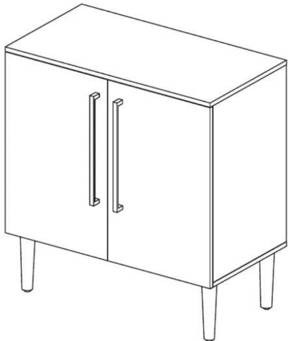
Console Cabinet CF6122
natural_image
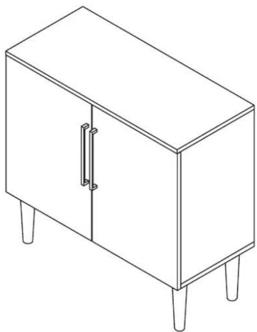
Line drawing of a simple cabinet with two doors and four legs (no text or symbols)PART LIST
A_2 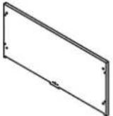 | B_2 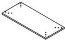 | C_2 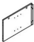 | D_2 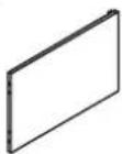 | E_2 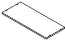 | |||||
| Top Panel1 PC | Bottom Panel1 PC | Left Side Panel1 PC | Right Side Panel1 PC | Adjustable Shelf1 PC | |||||
F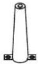 | G_2 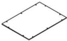 | H_2 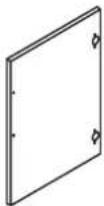 | I_2 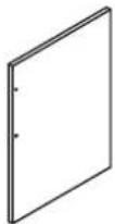 | J_2 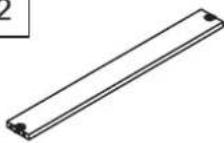 | |||||
| Leg4 PCS | Back Panel2 PCS | Left Door Panel1 PC | Right Door Panel1 PC | Back Connecting Rail1 PC |
HARDWARE LIST
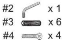
| #1 | #2 | #3 | #4 | #5 | |||||
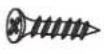
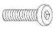 M6 x 13 M6 x 13 |  M4 M4 |  M8 x 30 M8 x 30 |  M6 x 25 M6 x 25 | 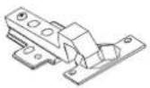 | |||||
| Short Bolt8 PCS (Extra 1) | Allen Wrench1 PC | Wood Dowel12 PCS (Extra 1) | Long Bolt8 PCS (Extra 1) | Door Hinge4 PCS | |||||
| #6 | #7 | #8 | #9 | #10 | |||||
 ∅3.5 x 15 ∅3.5 x 15 | 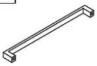 |  M4 x 18 M4 x 18 |  ∅8 x 16 ∅8 x 16 |  ∅7 x 2.5 x 12 ∅7 x 2.5 x 12 | |||||
| Small Screw24 PCS (Extra 1) | Handle2 PCS | Round Head Bolt4 PCS | Shelf Pin4 PCS (Extra 1) | Large Screw20 PCS (Extra 1) | |||||
| #11 | |||||||||
 | |||||||||
| Safety Strap Kit1 PC | |||||||||
ADDITIONAL TOOLS (Not Provided)
Note: It is not recommended to use power tools during assembly.
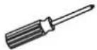
Phillips Head Screwdriver
Please do not use tools to assemble this unit unless specifically indicated.
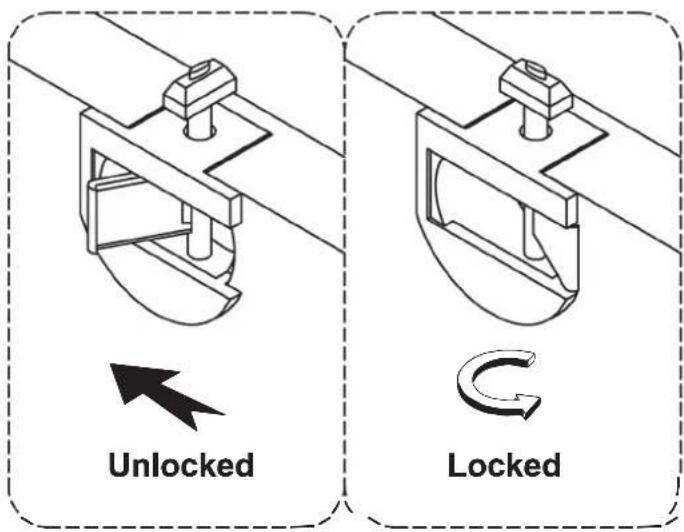
Reference the images above any time the instructions state "lock the hardware".
Note: Be sure to check all hardware is locked when completed.
Note: Wood dowels are intended for alignment. Additional clearance between wood dowel and pre-drilled hole is intentional for ease of assembly.
Step 1. Lay bottom panel (part B2) upside down on a soft surface, such as carpet, as shown below. Attach legs (part F) to bottom panel (part B2) using short bolts (part #1) and allen wrench (part #2).
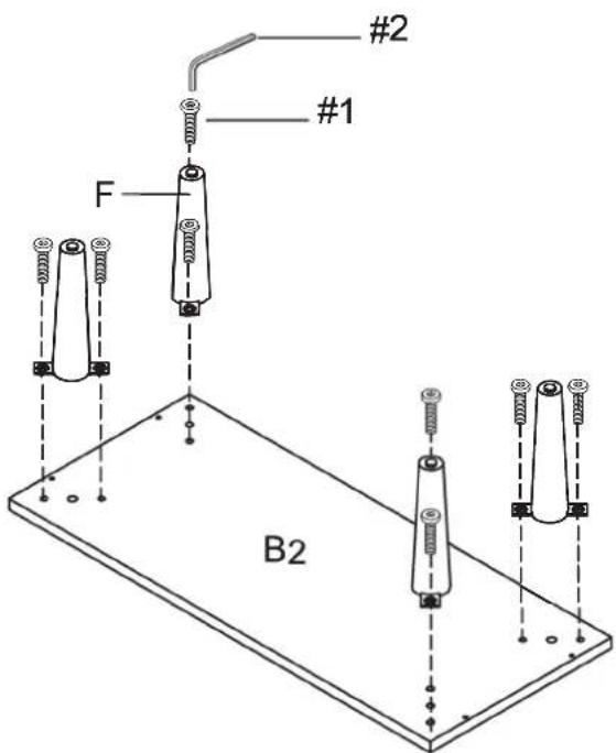
1 6 x 8
2 x 1
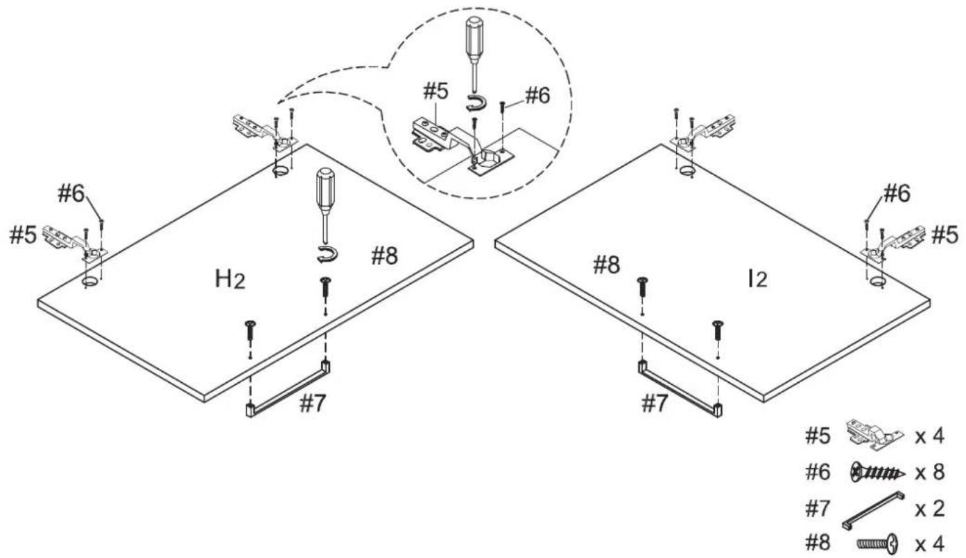
Step 2. Attach door hinges (part #5) to left door panel (part H2) and right door panel (part I2) using small screws (part #6) and phillips head screwdriver. Attach handles (part #7) to left door panel (part H2) and right door panel (part I2) using round head bolts (part #8) and phillips head screwdriver.
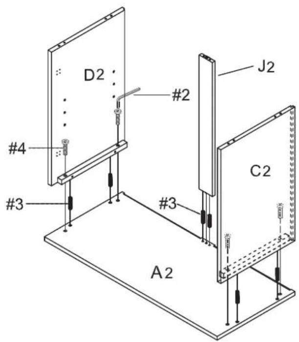
Step 3. Attach left side panel (part C2) and right side panel (part D2) to top panel (part A2) using allen wrench (part #2), wood dowels (part #3) and long bolts (part 4). Attach back connecting rail (part J2) to top panel (part A2) using wood dowels (part #3) and lock the hardware.
Step 4. Attach assembled unit (parts B2 & F) to assembled unit (parts A2, C2, D2 & J2) using allen wrench (part #2), wood dowels (part #3), long bolts (part #4) and lock the hardware.
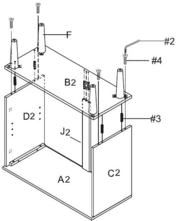
2 x 1
3 x 6
4 x 4
4 x 4
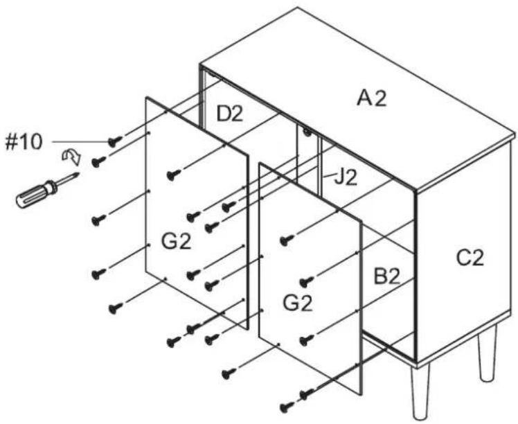
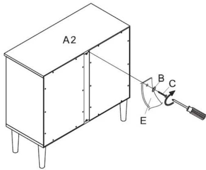
Step 5. Carefully turn unit upright. Attach back panels (part G2) to assembled unit (parts A2, B2, C2, D2 & J2) using large screws (part #10) and phillips head screwdriver.
Step 6. Insert shelf pins (part #9) into desidered position on left side panel (part C2) and right side panel (part D2). Slide adjustable shelf (part E2) into place.
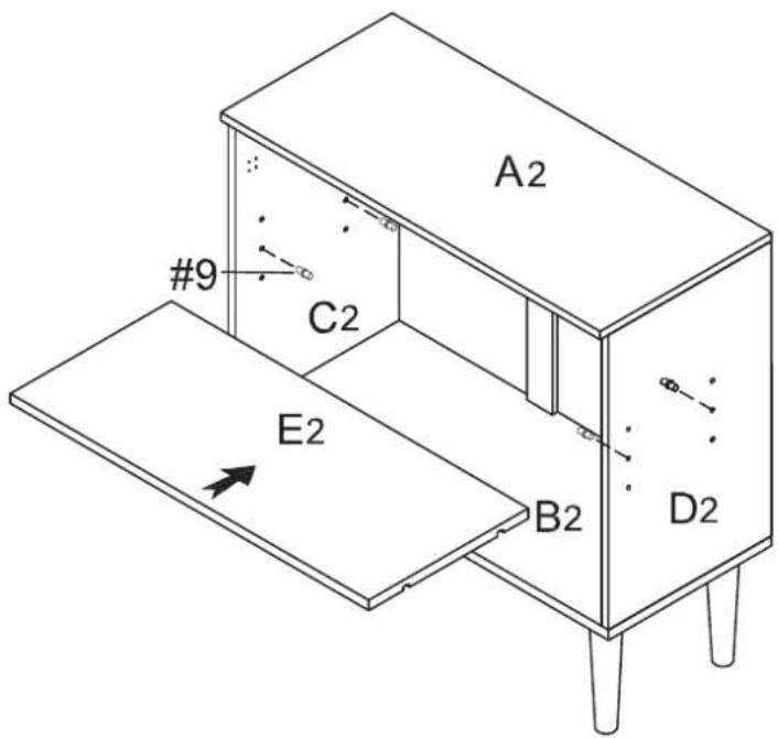
9 ×4
Step 7. Attach left door panel (part H2) to left side panel (part C2) using installed door hinges (part #5), small screws (part #6) and phillips head screwdriver.
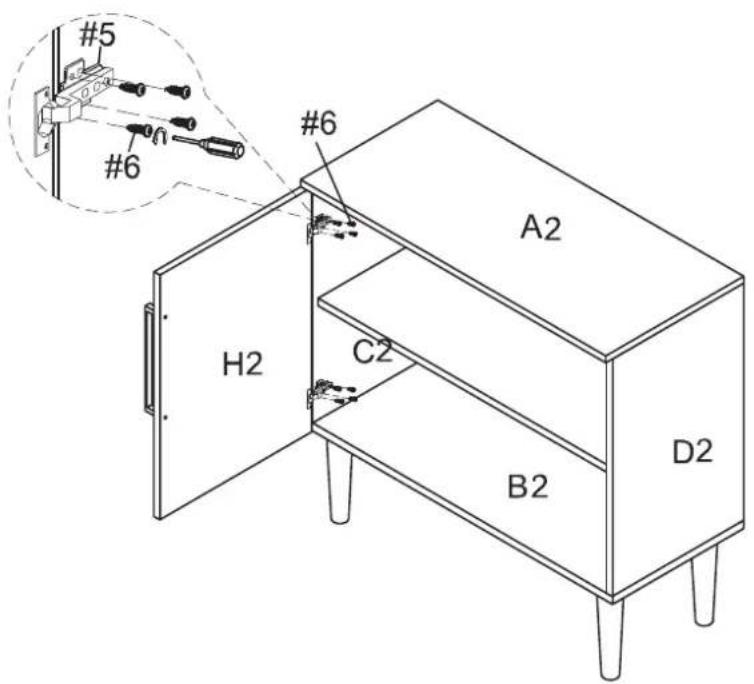
6 ×8
Step 8. Attach right door panel (part I2) to right side panel (part D2) using installed door hinges (part #5), small screws (part #6) and phillips head screwdriver.
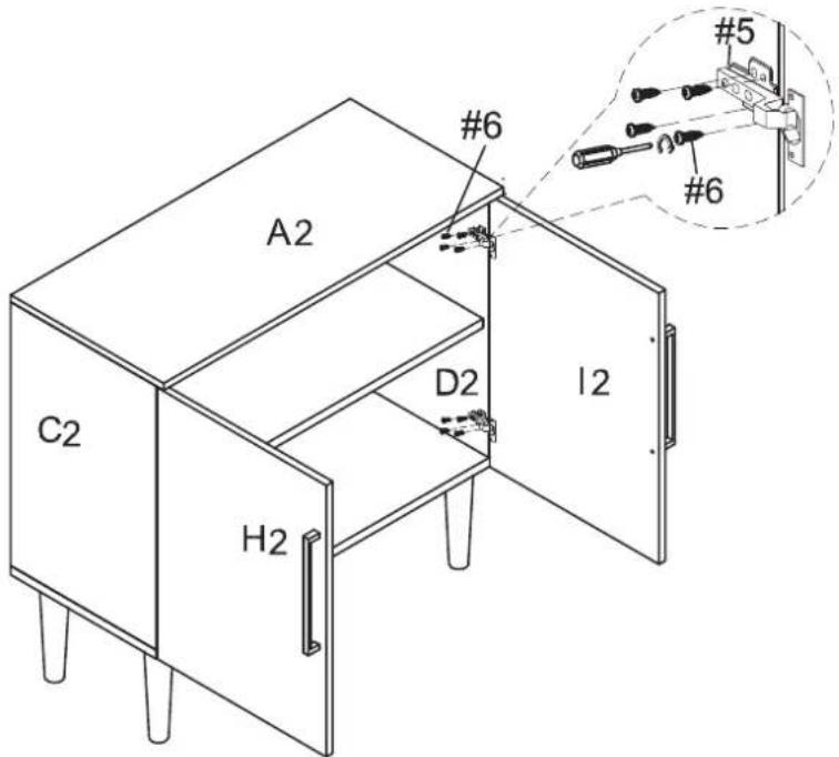
6 ×8
natural_image
Line drawing of a simple cabinet with four legs and a double door (no text or symbols)| #11 | A | B | C | D | E |
 |  | [y3w2] | 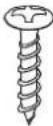 D8 x 3/4" D8 x 3/4" | [D2X5]D8 x 1-1/2" | 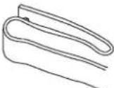 |
| Safety Strap Kit1 PC | Wall Anchor1 PC | Washer2 PCS | Short Screw1 PC | Long Screw1 PC | Safety Wall Strap1 PC |
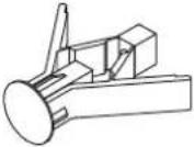
SAFETY WALL STRAP INSTALLATION
Note: It is highly recommended to install this safety strap kit to prevent tipping, damage and/or injury.
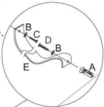
- Insert short screw (C) through washer (B) and safety wall strap (E) and attach to back of top panel (part A2) using phillips head screwdriver.
- Drill a 11/32"(6mm) hole where you want to secure the unit. The drilled hole will be at the same height as the hole in back of top panel (part A2) where safety wall strap (E) is attached. Tap wall anchor (A) into the hole.
- Insert long screw (D) through washer (B) and safety wall strap (E) into wall anchor (A) using a phillips head screwdriver.
Note: This item is not intended for clothing storage use.
Wall
WARNING

Children have died from
furniture tipover. To reduce the risk of furniture tipover:
- ALWAYS install tipover restraint provided.
- NEVER put a TV on this product.
- NEVER allow children to stand, climb or hang on drawers,
doors, or shelves. - NEVER open more than one drawer at a time.
- Place heaviest items in the lowest drawers.
This is a permanent label.
Do not remove!
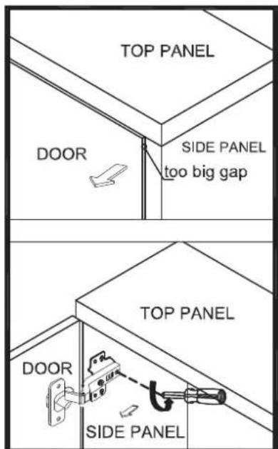
ADJUST YOUR DOORS TO MAKE THE GAPS MORE EVEN (OPTIONAL).
STEP 1
Open the door
STEP 2
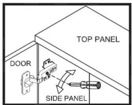
Adjust the gap between door panel and side panel
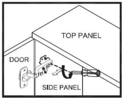
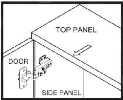
Loosen the screw indicated a little, adjust the hinge to right position (see step 2a & 2b), then tighten the screw.
STEP 2a MOVE DOOR IN
Push the hinge back a little.
STEP 2b MOVE DOOR OUT
Pull the hinge forward a little.
STEP 3
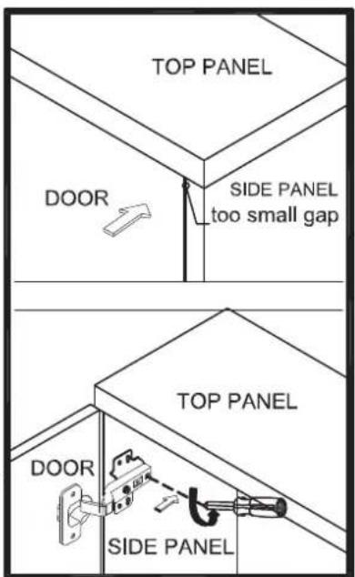
To adjust the gap between two door
Loosen or tighten the screw indicated a little to adjust the gap between doors panels (see step 3a & step 3b)
STEP 3a MOVE DOOR RIGHT
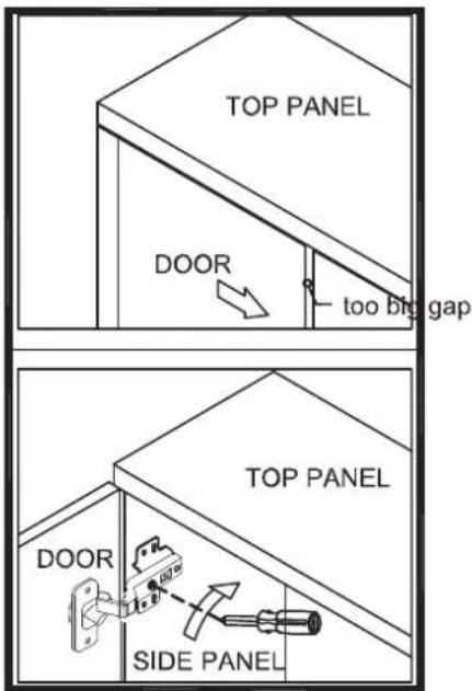
Turn the screw clockwise a little as shown to make the gap small.
STEP 3b MOVE DOOR LEFT
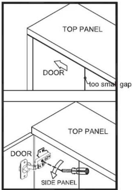
Turn the screw counterclockwise a little as shown to make the gap big.