FW3 - Đèn flash SMDV - Hướng dẫn sử dụng miễn phí
Tìm hướng dẫn sử dụng thiết bị miễn phí FW3 SMDV ở định dạng PDF.

Câu hỏi của người dùng về FW3 SMDV
0 câu hỏi về thiết bị này. Trả lời những câu bạn biết hoặc đặt câu hỏi riêng.
Đặt câu hỏi mới về thiết bị này
Tải xuống hướng dẫn cho thiết bị của bạn Đèn flash ở định dạng PDF miễn phí! Tìm hướng dẫn của bạn FW3 - SMDV và lấy lại thiết bị điện tử của bạn. Trên trang này được đăng tải tất cả các tài liệu cần thiết để sử dụng thiết bị của bạn. FW3 thương hiệu SMDV.
HƯỚNG DẪN NGƯỜI DÙNG FW3 SMDV
Flash Trigger & Release
FLASH Wave-Ⅲ
USER GUIDE
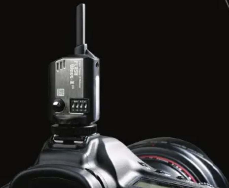
natural_image
Close-up of a black Fiji DSLR camera with attached digital camera module against black background (no visible text or symbols)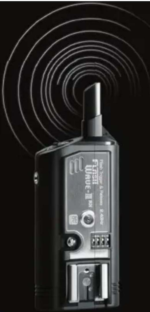
natural_image
Black Fiji 3.0 RF device with visible signal waves and control buttons (no readable text or symbols)Key Features of FlashWave-III
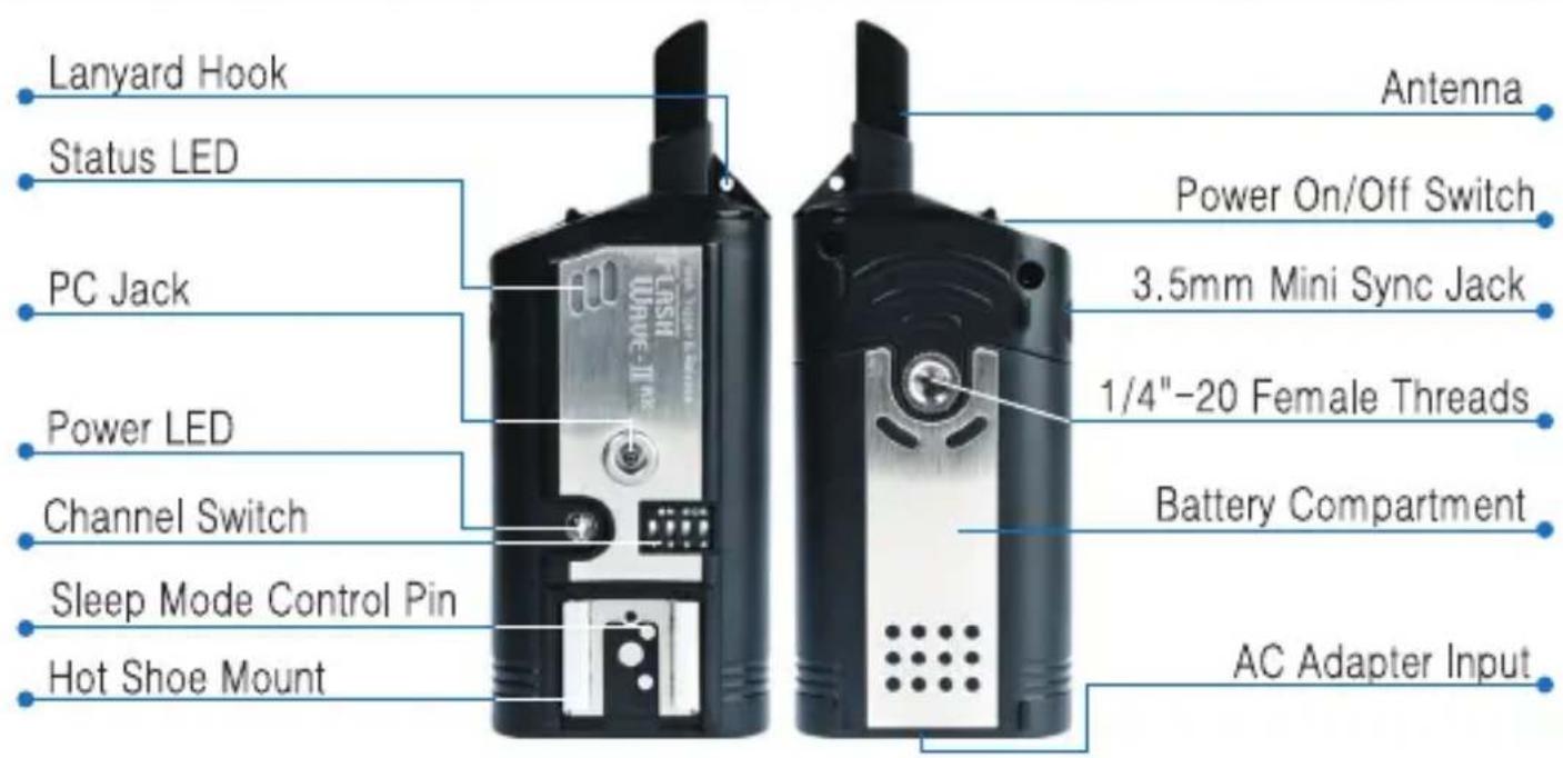
• Built in hot shoe on the receiver unit
- Sync Speed of up to 1/250 sec
● Ability to trigger flash up to 8 frames per second
• Maximum range of 180 meters (approx. 600 feet)
• 2.4 GHz frequency operation to minimize radio interference
- Sixteen selectable channels
- Ability to function as a camera shutter release (with optional cables)
- Ability to operate in extreme temperatures (-20°C \~ 50°C)
- Multiple ports for connecting to portable flash or studio strobes (for DC model)
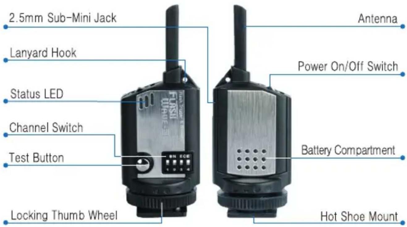
Part Reference - Transmitter
natural_image
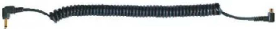
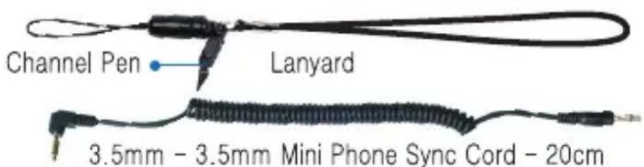
Coiled black cable with terminal connectors (no text or symbols visible)PC Male to 2.5mm Sub-Mini Phone Sync Cord - 20cm
Part Reference - DC Receiver
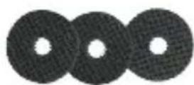
Rubber Washer
natural_image
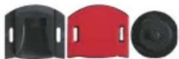
Three black plastic components with curved and circular features, no visible text or symbolsAdhesive-backed Hotshoe & Shoe-to-1/4" with Thumb Wheel Lock
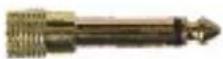
3.5mm to 6.3mm Sync Adapter
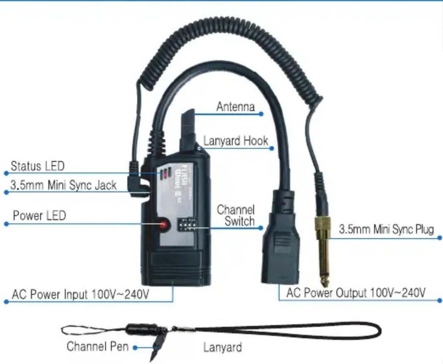
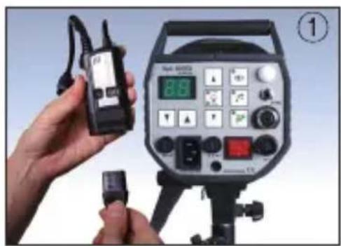
Part Reference - AC Receiver
Transmitter - Set Up
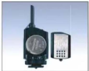
Install a CR2450 3V Lithium coin cell into the transmitter
There are two ways to connect the transmitter to your camera.
- Slide the transmitter in to the hot shoe of your camera so that the channel switch faces the photographer.
- Use the included 2.5mm phone jack to connect the transmitter to your camera equipped with a PC jack.
Switch on the power of the transmitter. Transmitter has a test button to verify your set up.
NOTE - FlashWave-III system is not designed to perform TTL mode of flash units. Also this system is not able to operate properly when the camera is using Live View mode. Therefore it is necessary to set the camera to regular mode and flash unit to set to Manual Mode.
natural_image
Two electronic devices with visible speaker and antenna (no text or symbols)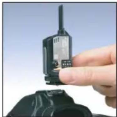
natural_image
Close-up of a hand holding a walkie-talkie device with a black plastic case (no visible text or symbols)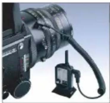
natural_image
Close-up of a black camera with attached cable and stand (no visible text or symbols)DC Receiver - Set Up
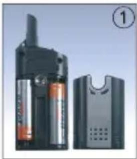
- Install two AA batteries into the receiver (observe the polarity of batteries as indicated).
- Ensure your flash lights are turned off.
- a - For portable flash unit, mount the portable flash directly on the receiver's hot shoe.
b - For strobes, connect the receiver with an appropriate cable and adapter. (A cable with 3.5mm mono plug and 6.3mm plug adapter are included.)
- Ensure the channel on the receiver matches that of the transmitter.
- Rubber washers can help the receiver fit tightly on the mount head of the tripod.
- Plastic hot shoe grip and screw are supplied to allow attaching the receiver to strobe if desired. The plastic hotshoe grip possesses an adhesive surface by which it can be attached in variety of places.
- Turn on the flash and receiver unit.
natural_image
Exterior view of a portable electronic device with battery pack and speaker unit (no visible text or symbols)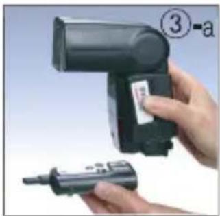
natural_image
Close-up of a hand holding a handheld device with a label and a small pen, no visible text or symbols.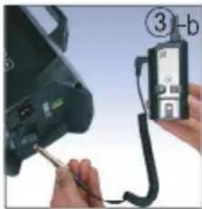
natural_image
Close-up of hands using a handheld device to connect a contact lens into a digital camera (no visible text or symbols)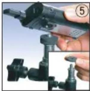
natural_image
Close-up of a hand holding a handheld electronic device with a close-up inset showing the same mechanical component (no visible text or symbols)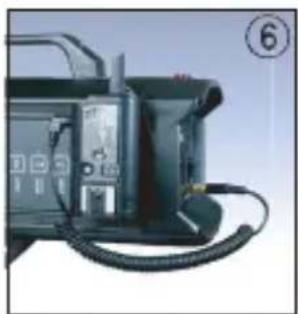
natural_image
Close-up of a black electronic device with coiled cable and indicator lights (no visible text or symbols)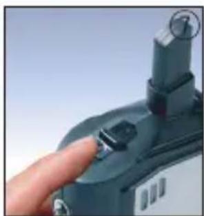
natural_image
Close-up of a hand pressing a button on a device (no visible text or symbols)AC Receiver - Set Up
- Unplug the AC power cord from the studio strobe and plug it into the bottom of the Flash Wave-III AC Receiver.
- Insert the power cord of the receiver into the AC power socket of the strobe.
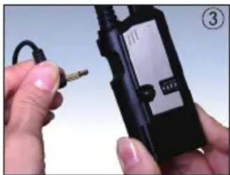
- Connect the supplied 3.5mm sync cord to the receiver.
- Insert the 3.5mm sync cord of the receiver into the sync socket of the strobe. If your strobe uses 6.3mm sync socket to connect the receiver, connect the supplied 6.3mm sync adapter to the 3.5mm mono plug cord.
- Once the Strobe power is turned on, the receiver will be turned on automatically. Power RED LED keeps blinking every two second. The Status LED on the receiver blinks RED to indicate synchronization.
natural_image
Person holding a walkie-talkie next to an analog photography recording device (no visible text or symbols on the device itself)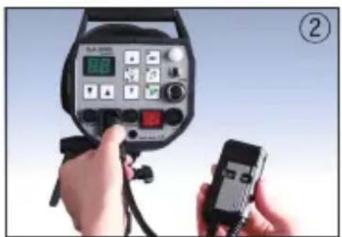
natural_image
Close-up of hands holding a black walkie-talkie device with a small connector, no visible text or symbols on the device itself.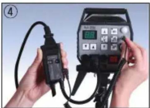
natural_image
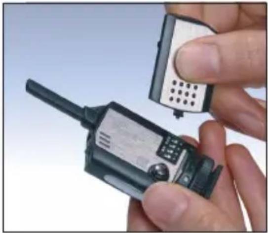
Close-up of hands holding a handheld electronic device connected to a digital display (no visible text or symbols)Changing Channels
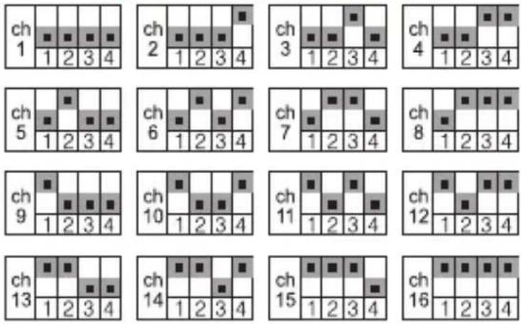
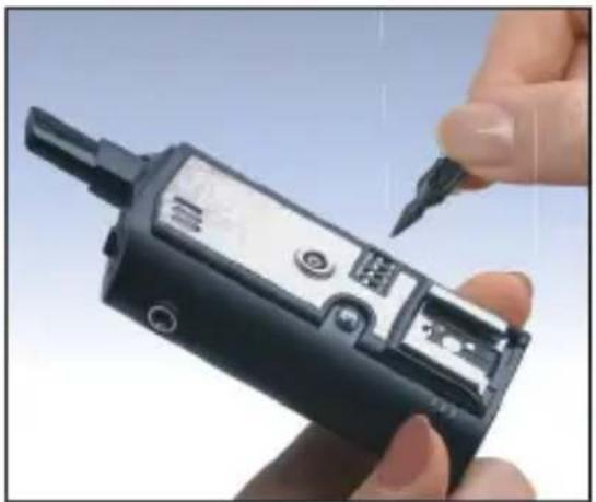
FlashWave-III has 16 channels. To operate, the transmitter and receiver must be on the same channel. To change the channel, follow these steps:
- Turn off the transmitter and the receiver.
- Battery cover of the transmitter has a minipin to help you adjust the channel switches.
- Select the desired channel on the transmitter and the receiver
- Turn on the transmitter and the receiver.
natural_image
Close-up of a hand holding a walkie-talkie device with a small electronic device inserted (no visible text or symbols)* Adjust to the same channel
natural_image
Close-up of a hand holding a black handheld electronic device with a pen inserted (no visible text or symbols)Shutter Release Mode - Triggering Camera
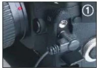
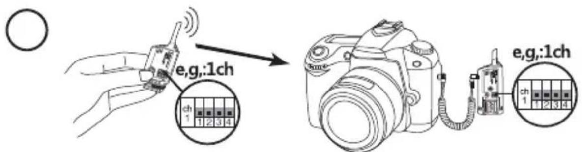
FlashWave-III can be used to trigger a remote camera. Your camera must be equipped with an electronic shutter release input. An additional accessory cable (not included) is required. With the proper cable, follow these easy steps:
natural_image
Close-up of a camera lens and adjustment knobs (no visible text or symbols)- Locate the electronic shutter release input on your camera.
- Connect FlashWave-III receiver to the camera's electronic shutter release input using the appropriate accessory cable.
- Ensure the transmitter and the receiver are set to the same channel.
- Power on both the transmitter and receiver.
- Press TEST button on the transmitter unit to operate auto focus function and shutter function of the remote camera.
- Wireless Bulb Shooting: Set up your camera on Bulb mode. Press test button on the transmitter fully until the Red LED light off on the transmitter. When you will see the Red LED from the receiver come on, it signals the shutter is open. To end the Bulb Shooting, press the test button shortly.
natural_image
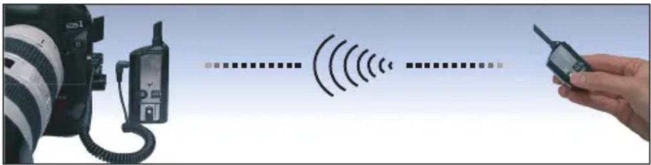
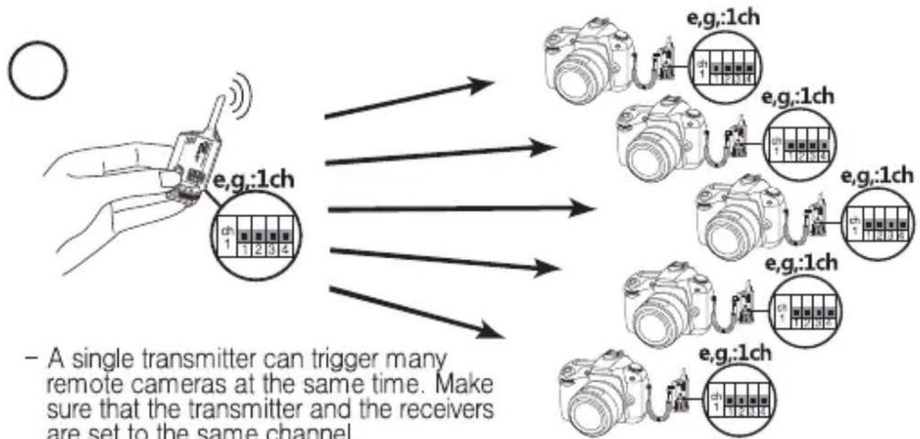
Illustration showing a DSLR camera connected to a hand holding a handheld device with signal waves (no text or symbols)hutter Release Mode - Correct Set Up
- Ensure both the transmitter and the receiver are set to the same channel. Press the test button on the transmitter to trigger the remote camera.
flowchart
graph TD
    A["Hand holding device e.g.:1ch"] --> B["Camera 1: 12 3 4"]
    A --> C["Camera 1: 12 3 4"]
    A --> D["Camera 1: 12 3 4"]
    A --> E["Camera 1: 12 3 4"]
    A --> F["Camera 1: 12 3 4"]
    A --> G["Camera 1: 12 3 4"]
    A --> H["Camera 1: 12 3 4"]
    A --> I["Camera 1: 12 3 4"]
    A --> J["Camera 1: 12 3 4"]
    A --> K["Camera 1: 12 3 4"]
    A --> L["Camera 1: 12 3 4"]
    A --> M["Camera 1: 12 3 4"]
    A --> N["Camera 1: 12 3 4"]
    A --> O["Camera 1: 12 3 4"]
    A --> P["Camera 1: 12 3 4"]
    A --> Q["Camera 1: 12 3 4"]
    A --> R["Camera 1: 12 3 4"]
    A --> S["Camera 1: 12 3 4"]
    A --> T["Camera 1: 12 3 4"]
    A --> U["Camera 1: 12 3 4"]
    A --> V["Camera 1: 12 3 4"]
    A --> W["Camera 1: 12 3 4"]
    A --> X["Camera 1: 12 3 4"]
    A --> Y["Camera 1: 12 3 4"]
    A --> Z["Camera 1: 12 3 4"]
    A --> AA["Camera 1: 12 3 4"]
    A --> AB["Camera 1: 12 3 4"]
    A --> AC["Camera 1: 12 3 4"]
    A --> AD["Camera 1: 12 3 4"]
    A --> AE["Camera 1: 12 3 4"]
    A --> AF["Camera 1: 12 3 4"]
    A --> AG["Camera 1: 12.5"]
    A --> AH["Camera 1: 12.5"]
Shutter Release Mode - Correct Set Up
flowchart
graph TD
    A["Camera"] -->|e.g.,:2ch| B["Switch"]
    B --> C[" relay"]
    C --> D["Camera Module 1"]
    C --> E["Camera Module 2"]
    C --> F["Camera Module 3"]
    C --> G["Camera Module 4"]
    style A fill:#f9f,stroke:#333
    style B fill:#ccf,stroke:#333
    style C fill:#cfc,stroke:#333
    style D fill:#fcc,stroke:#333
    style E fill:#cff,stroke:#333
    style F fill:#ffc,stroke:#333
    style G fill:#cfc,stroke:#333
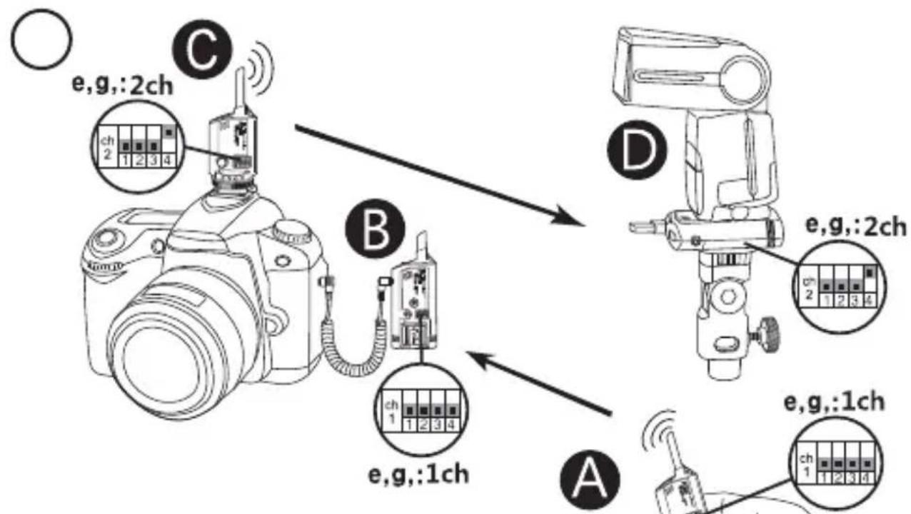
- To remotely trigger a camera and flash at the same time, set the transmitter Ⓑ and receiver Ⓤ triggering the camera to channel no. 1 and set the transmitter Ⓑ and receiver Ⓓ firing the flash to channel no. 2.
Shutter Release Mode - Incorrect Set Up

- When the transmitter Ⓐ is activated by the camera, the flash Ⓐ will fire but remote camera Ⓑ cannot work properly.
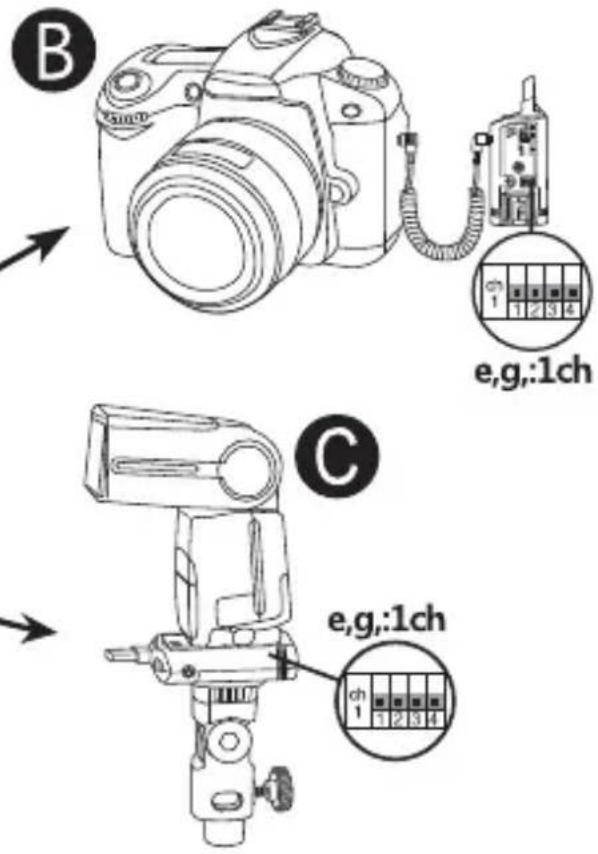
Shutter Release Mode - Incorrect Set Up
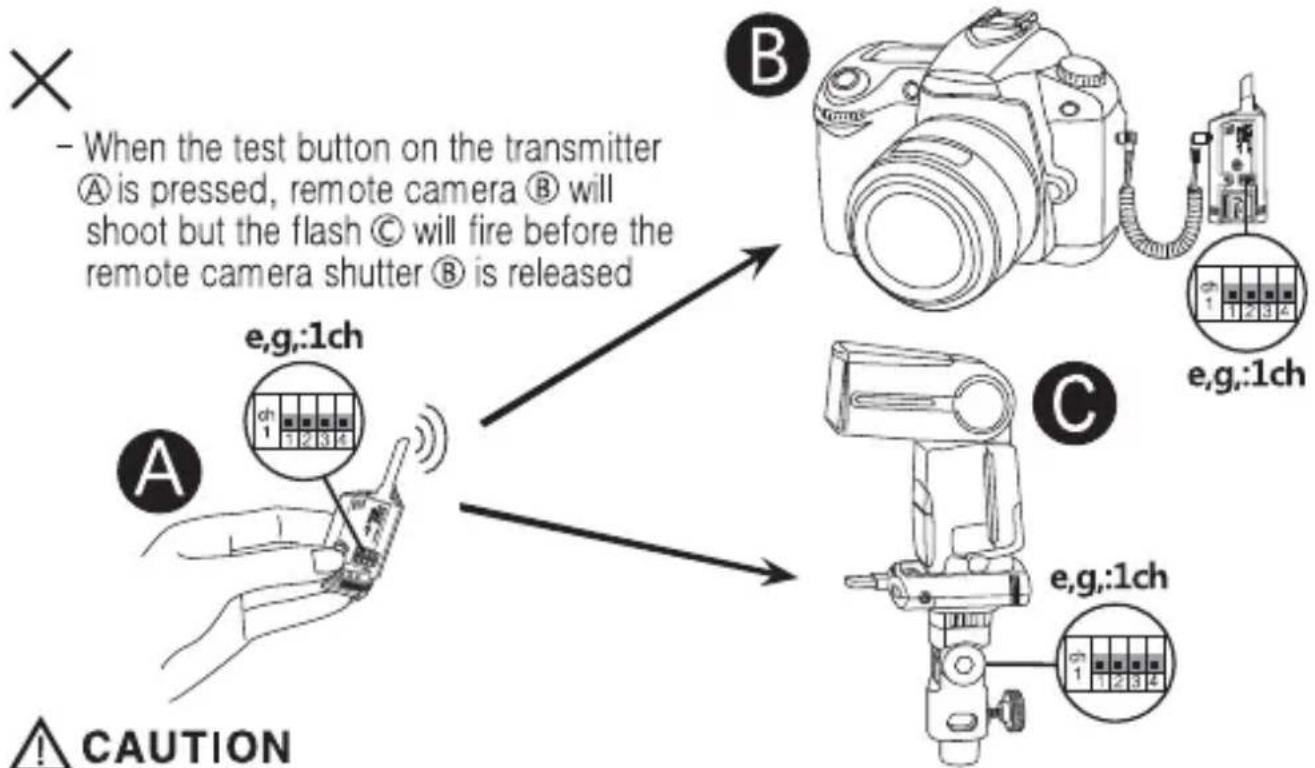
PLEASE NOTE: A single FlashWave III transmitter cannot trigger both the remote camera and flash/strobe units. To remotely trigger a camera and trigger flash to sync with the camera, two transmitter units operating on two different channels are required. Because cameras have shutter lag (delay inside a camera), when the receivers on the camera and flash are operating on the same channel, even if the signal from the single transmitter reaches the receivers at the same time, flash will normally fire before the shutter is released. Therefore, to remotely trigger a camera and flash, set the transmitter and receiver triggering the camera to channel X and set the transmitter and receiver triggering the flash to channel Y.
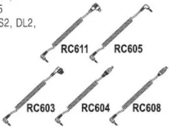
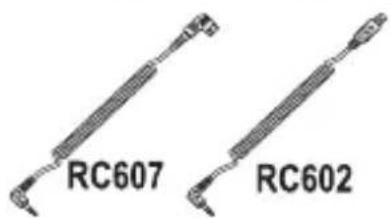
Accessory Camera Release Cable
To use your FlashWave-III System as a shutter release (i.e., to trigger your camera shutter), you'll need an additional camera release cable compatible with your camera. Following release cables are available as separate accessories. (These cables extends to approximately 25cm.)
RC611 - Canon 7D, 1DMarkIV, 1Ds MarkIII, 5D MarkII, 1Ds MarkII, 1Ds, 1D MarkIII, 1D MarkII, 1D, 5D, 50D, 40D, 30D, 20D, 10D, D60, D30, EOS 3, EOS1VHS, 1V
RC605 - Canon 550D, 500D, 1000D, 450D, 400D, 350D, 300D, EOS 30, 50, 500N, Kiss, 300, 88, 66, 55
Pentax K200D, K110D, K100D, K20D, K10D, S2, DL2, Ds, DL, *istD
Samsung GX-20, GX-10, GX-1L, GX-1S
Sigma SD15, SD14, SD10, SD9
Contax N1, N Digital
RC603 - Nikon D700, D300, D300S, D200, D100 (battery grip required), D3, D3S, D3X, D2, D2Xs, D2X, D2Hs, D2H, D1H, D1, F6, F5, F100, F90X, F90
Fuji S5Pro, S3Pro
Kodak DCS Pro SLR/N
RC604 - Nikon D70s, D80
RC608 - Nikon D90
RC607 - Sony a900, a850, a700, a350, a300, a200, a100
Minolta 7D, 5D, 7i, 7, 5, A1, A2
RC602 - Olympus PEN E-PL1, E-P1, E-P2, E620, E520, E510, E450, E420, E30, E410, E400, SP-570UZ, SP-560UZ, SP-510UZ
Trouble shooting
Receiver is on but On/Off LED does not blink
- Insert fresh batteries in a right battery polarity.
Status LED on the receiver does not respond when transmitter "Test button" is pressed.
- Make sure that both the transmitter and receiver are on the same channel.
Flash does not work, even though receiver is responding to signals from the Transmitter.
- Check the flash unit is functional when removed from the receiver.
- Check all connections.
– Try interchanging between hot shoe and sync cable.
Status LED on the receiver blinks continuously even though "Test Button" is not pressed.
- Disconnect the unit from camera or flash and reconnect them.
- Check that the transmitter and receiver are on the same channel.
Receiver does not perform the Bulb shooting even though the receiver is powered on.
-Insert fresh batteries on the receiver in a right battery polarity.
Working extended range
- Sync speed and working distance are affected by radio interference and obstructions. Avoid having a large hill, concrete, metal or water obstructions between the transmitter and receiver. Move the transmitter and receiver at least one meter away from the ground. Often moving the transmitter and receiver a few meters will improve the situation.
Specifications
| Transmitter | DC Receiver | AC Receiver | |
| Frequency | 2.427 GHz ~2.457 GHz | ||
| Number of channels | 16 | ||
| Max range | Up to 180 meters or 600 feet | ||
| Max sync speed | 1/250 sec | ||
| Triggering Voltage | 3 volts (DC) | ||
| Max flash voltage handling by the receiver | Up to 300 volts (DC) | Up to 300 volts (DC) | |
| Sync ports | 2.5mm sub-mini jack | Female 3.5mm sync jack Female hot shoe mount Female PC sync jack AC adapter input | IEC cord-25mm Female IEC AC power input 3.5mm sync jack-coiled cord |
| Battery life (approx.) | 1×CR2450(3V)/one year, up to 20,000 triggers | 2×AA 1.5V /150 hours on-time | AC 100V-240V 50-60HZ |
| Dimensions | 31mm×26mm×80mm | 43mm×25mm×110mm | 43mm×25mm×110mm |
| Weight | 20g | 60g | 80g |
FCC Compliance & CE Statements
This equipment has been tested and found to comply with the limits for a Class B digital device pursuant to part 15 of the FCC Rules. These limits are designated to provide reasonable protection against harmful interference in a residential installation.
This equipment generates, uses, and can radio frequency energy, and, if not installed and used in accordance with instructions, may cause harmful interference to radio communications.
There is no guarantee that interference will not occur in a particular installation. If this equipment does cause harmful interference to radio or television reception, which can be determined by turning the equipment ON or OFF, the user is encouraged to try to correct the interference by one or more of the following measures.
- Reorient or relocate the receiving antenna.
- Increase the distance between the equipment and the receiver.
This device complies with Part 15 of the FCC Rules. Operation is subject to the following two conditions:
- This device may not cause harmful interference.
- This device must accept any interference received, including interference that may cause undesired operation
Any changes or modifications (including the antennas) made to this device that are not expressly approved by the manufacturer may void the user's authority to operate the equipment.
FC ID WU2SMRS0911
CE Statements

This device has been tested and found to comply with the requirements set up in the council directive on the approximation of the law of member states relating to R&TTE Directive 1999/5/EC