TL-72 - Máy may JUKI - Hướng dẫn sử dụng miễn phí
Tìm hướng dẫn sử dụng thiết bị miễn phí TL-72 JUKI ở định dạng PDF.

Câu hỏi của người dùng về TL-72 JUKI
0 câu hỏi về thiết bị này. Trả lời những câu bạn biết hoặc đặt câu hỏi riêng.
Đặt câu hỏi mới về thiết bị này
Tải xuống hướng dẫn cho thiết bị của bạn Máy may ở định dạng PDF miễn phí! Tìm hướng dẫn của bạn TL-72 - JUKI và lấy lại thiết bị điện tử của bạn. Trên trang này được đăng tải tất cả các tài liệu cần thiết để sử dụng thiết bị của bạn. TL-72 thương hiệu JUKI.
HƯỚNG DẪN NGƯỜI DÙNG TL-72 JUKI
MODEL TL-72
SINGLE NEEDLE LOCKSTITCH
TAILORING SEWING MACHINE
INSTRUCTION BOOK
&
PARTS BOOK
natural_image
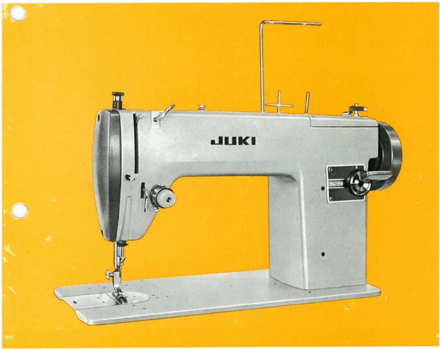
Vintage JUKI sewing machine on a yellow background (no visible text or symbols)TOKYO JUKI INDUSTRIAL CO., LTD.
MODEL TL-72 SPECIFICATIONS
| Sewing speed | : Normal 1,500 stitches/min; Maximum 1,800 stitches/min |
| Stitch length | : 5mm maximum |
| Needle bar stroke | : 32mm |
| Rise of the presser foot | : 7mm, 12mm (knee lifter) |
| Needle for use | : DB × 1 |
| Lubrication system | : Manual |
| Lubrication oil | : New Deflix Oil No.1 |
| Transmission belt | : Round leather belt (treadle type) 7mm dia. V-belt (motor operated type) |
| Bed size | : 399mm × 178mm |


CONTENTS
I. GENERAL DESCRIPTION 1
II. OPERATION & ADJUSTMENT OF THE MACHINE ..... 1
-
Cautions on operation 1
-
Lubrication 2
-
Thread 2
-
Attaching the needle 2
-
Threading the machine (needle thread) 3
-
Removing the bobbin case and the bobbin 4
-
Winding the bobbin 4
-
Inserting the bobbin 5
-
Inserting the bobbin case 6
-
Drawing up the bobbin thread 6
-
Starting a stitch 6
-
Thread tension 6
-
Adjusting the stroke the tension of the thread take-up spring ..... 7
-
Adjusting the stitch length 8
-
Pressure of the presser foot 9
-
Height of the feed dog 9
-
Mounting and removing the sewing hook 9
-
Relation between the needle and the hook point 10
-
Spool stand 12
III. INSTALLING THE OVERHEAD LIGHT 13
IV. CAUSES OF TROUBLE 14
PARTS BOOK 15


I. GENERAL DESCRIPTION
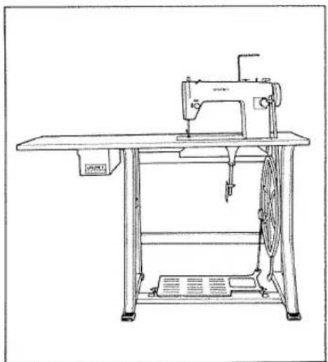
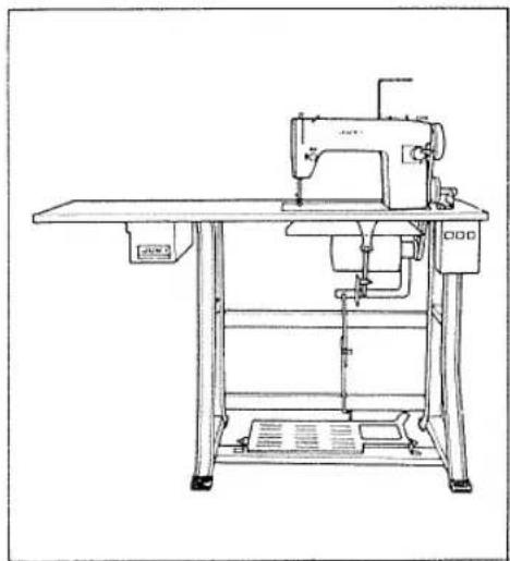
JUKI Model TL-72 is a single-needle lockstitch sewing machine with the twice-rotation sewing hook which has ideal characteristics suitable for sewing various articles of clothing, and in particular, for the use in the home industry, tailor shops and dressmaking shops.
natural_image
Line drawing of a vintage sewing machine with a circular cutter and base plate (no text or symbols)Fig.1 (A) Treadle type
natural_image
Line drawing of a sewing machine on a workbench (no text or symbols)Fig.1 (B) Motor driven type
§1. OPERATION & ADJUSTMENT OF THE MACHINE
1. Cautions on operation
Take care of the following matters in order to operate the machine smoothly without any trouble.
a) Be sure to turn the hand wheel toward you.
b) When not in operation, you must not let down the presser foot or turn the hand wheel with the needle threaded. Never fail to keep the slide plate closed.
c) Use a proper needle fit for the thread thickness so as to allow the thread to pass freely through the eye of the needle by referring to the following table. The size of the needle used is to be DB×1.
| Needle No. (DB×1) | Thread | |
| 11 | 80~100 | Cotton threadSilk thread |
| 14 | 50 | Cotton thread |
| 16 | 40~50 | Cotton thread |
| 18 | 30~40 | Cotton thread |
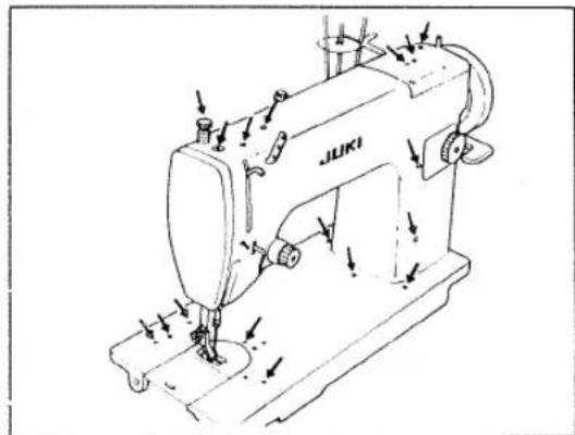
2. Lubrication
In order to add to the life of the machine and make it fulfill its function, never fail to lubricate the machine.
Fig.2 (B) shows the oiling points on the arm bed, while Fig.2 (A) shows those on the back surface of the bed at ① and ②.
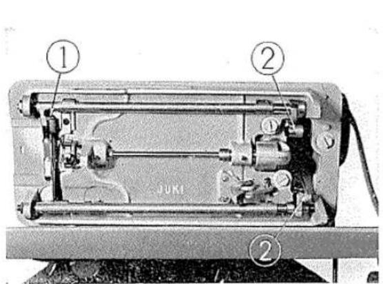
Fig.2 (A)
natural_image
Line drawing of a sewing machine labeled 'JUKI' with no visible text or symbols beyond the labelFig.2 (B)
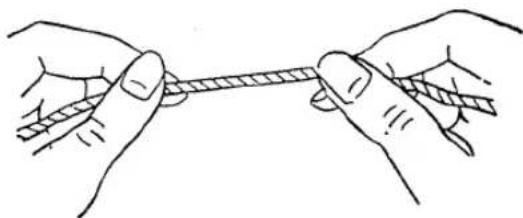
3. Thread
Use only the left-hand twisted thread (z-twisted yarn) for the needle thread. For the bobbin thread, however, either right- or left-hand twisted thread may be used. In examining the twist of the thread, hold it between the thumb and the first finger of your each hand and twist it toward you with your right hand; if the left-hand twisted thread it will be wound still more tight, while the right-hand twisted thread will be untwisted and loosened.
natural_image
Illustration of two hands tying a rope knot (no text or symbols)Fig. 3
4. Attaching the needle (Fig.4)
Turn the hand wheel slowly toward you until the needle bar gets to its highest position and then loosen the needle clamp screw. Subsequently, insert the shank of the needle fully into the groove on the needle bar until the said shank hits against the innermost end of the said groove, and securely tighten the needle clamp screw so that the longer groove on the needle facing to the left.
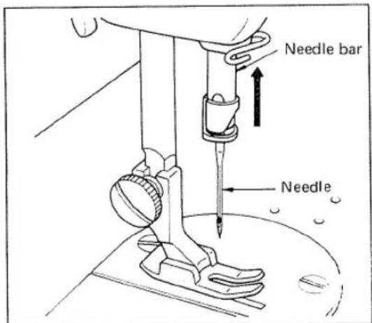
Fig. 4
5. Threading the machine (needle thread)
Thread the machine in accordance with Fig.5. (numerical order from ① to ⑪).
Turn the hand wheel toward you to keep the needle bar at its highest position.
Pass the thread from the spool upward through the passage ① and, after winding the thread counterclockwise once round the needle thread guide pin, pass the thread through the passage ② from rear to front. Then pass it through the holes on the three-hole thread eyelet ③, pass it in between the two tension discs ④ and lead it through the thread take-up spring ⑤ to the thread guide ⑥.
Then pull up such thread for passing it through the hole of the thread take-up lever ⑦ from right to left, pass the thread therefrom through the take-up thread guide ⑧, and pass it through in the order of the thread guide ⑨ on the needle bar bushing, the needle bar thread guide ⑩, and finally, the needle hole ⑪ from left to right. The thread should be pulled by about 15cm (about 6") out of the needle hole.
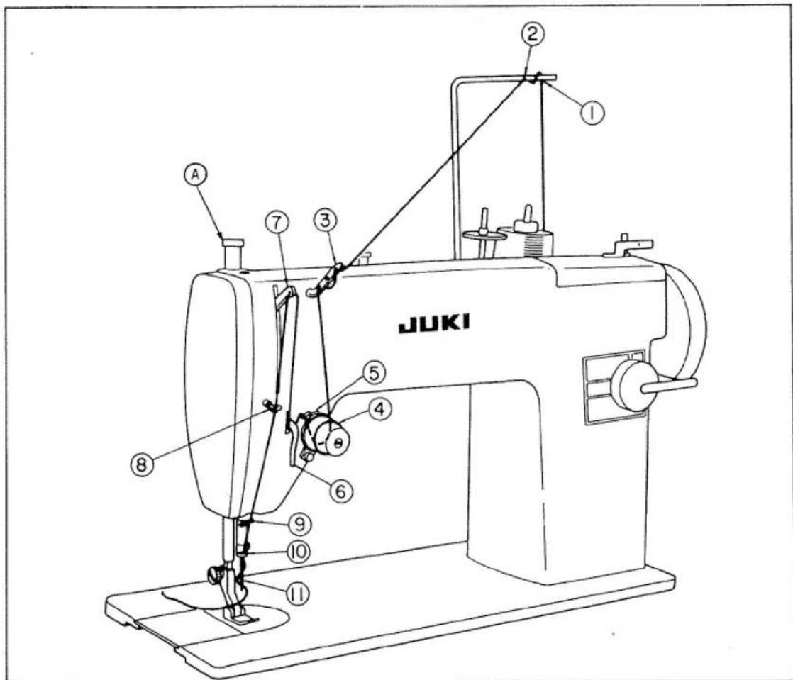
Fig. 5
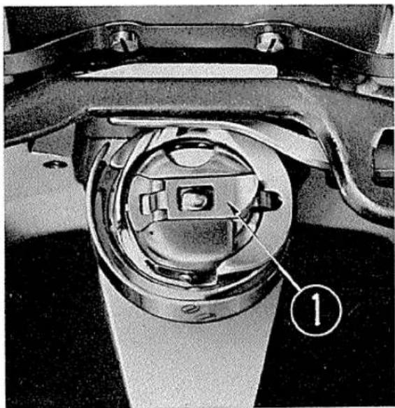
6. Removing the bobbin case and the bobbin
Turn the hand wheel toward you until the needle bar gets to its highest position, open the slide plate by pulling it to the left, put your left hand under the table to raise the latch (1) (Fig.6) with the thumb and the first finger, and then pull out the bobbin case. Since the bobbin would be kept within the bobbin case so long as the latch is raised, you should release the latch and hold the bobbin case upside down for removing the bobbin from the case.
natural_image
Close-up of a mechanical component with a circular housing and labeled part (1), no readable text or symbols present.Fig. 6
7. Winding the bobbin
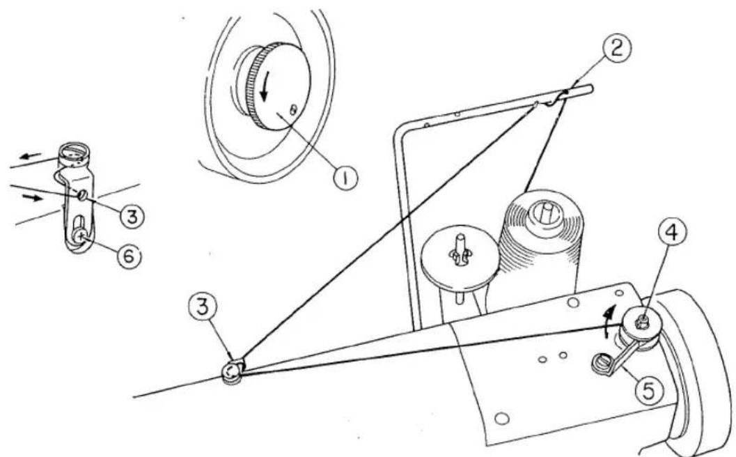
Fig. 7
As shown in Fig.7 and 8 turn the stop motion screw ① counterclockwise to allow the hand wheel to run idle. Pull out the thread from the spool through the hole ② located on the spool frame, pass it through a hole in the thread guide frame ③ from rear to front and pass the thread through the gap between the frame and the tension disc on the thread guide ③. Wind the thread several times round the bobbin and then insert the bobbin in such a manner as to allow the pin on the bobbin winder spindle ④ to fit into the notch on the bobbin. Then press the trip latch ⑤ against the bobbin to allow the pulley to come into contact with the hand wheel and wind the thread round the bobbin by turning the hand wheel toward you. When the thread is wound round the bobbin to its full, the trip latch ⑤ will come off the bobbin automatically to stop the rotation of the bobbin. If the thread would be wound one-sidedly, you should loosen the setscrew ⑥ on the thread guide frame, move the frame up and down, and tighten the setscrew at such position that may facilitate even winding of the thread.
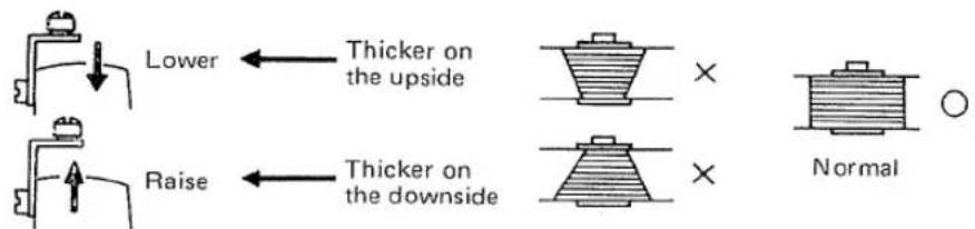
Fig. 8
(Note) When using fine thread such as tetoron thread, andaria thread and nylon thread, you should be fully careful of the adjustment of the thread tension on the bobbin winder. The thread tension used is to be around 30g (approximately the same as that of the thread in the bobbin case).
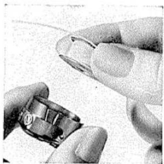
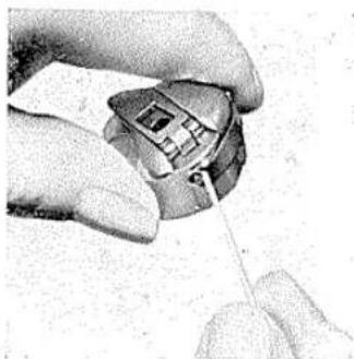
8. Inserting the bobbin
Holding the bobbin case and the bobbin with your left and right hands respectively as shown in the Fig.9 (A), insert the latter into the former.
Then pass the protruding thread portion into the thread passing opening ① on the rim of the bobbin case as shown in Fig.9 (B) and, while further pulling the thread, pass it under the thread tension spring ② and pull the thread out of the thread opening as shown in Fig.9 (C).
natural_image
Close-up of a hand holding a small electronic component, possibly a sensor or connector (no visible text or symbols)Fig.9 (A)
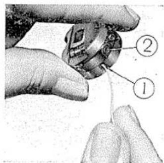
Fig.9 (B)
natural_image
Close-up of a hand holding a small electronic device with a coiled cable (no visible text or symbols)Fig.9 (c)
9. Inserting the bobbin case (Figs. 16 and 17)
Picking up the latch of the threaded bobbin case between the thumb and the first finger of your left hand, fix the bobbin case to the shaft of the sewing hook and, leaving the knob released, push the bobbin case further into the depth until the latch fits into the groove near the tip of the shaft. Finally, close the slide plate.
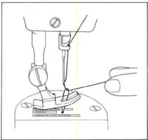
10. Drawing up the bobbin thread
While picking up the end of the needle thread coming out of the eye of the needle with your left hand, turn slowly the hand wheel toward you with your right hand to allow the needle bar to move down and up once. Then, when the needle gets to its highest position, pull up the needle thread, and the bobbin thread will come out of the eye of the needle caught by the needle thread.
Pass both of the needle thread and the bobbin thread together under the presser foot, leaving them extended on the far side (Fig.10).
natural_image
Line drawing of a sewing machine needle insertion into a base, showing the needle being inserted (no text or symbols)Fig. 10
11. Starting a stitch
Raise the needle to its highest position, lay the cloth to be sewn under the presser foot, let down the presser foot, and turn the hand wheel toward you to start the sewing operation. Since the cloth is fed automatically by the feed dog as you rotate the hand wheel, forcing the cloth may cause the bend or break of the needle.
12. Thread tension
In the sewing operation, perfect stitches are always required.
Normal condition is such that the needle thread and the bobbin thread may interloop at the center of the material thickness as shown in Fig.11 (A).
If either one of the needle thread and the bobbin thread has the tension higher than that of the other, the result will be such as shown in Fig.11 (B) and (C).
For adjusting the tension of the needle thread, turn the thread tension regulator dial. When the thread tension regulator dial is turned clockwise, the tension of the needle thread increases.
When the thread tension regulator dial is turned counterclockwise, then the said tension decreases.
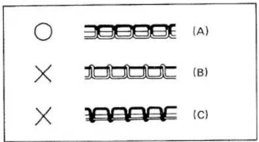
Fig. 11
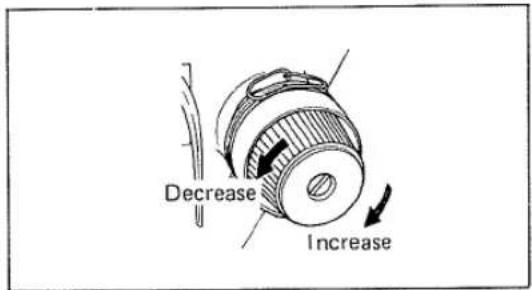
Fig. 12
In adjusting the tension of the bobbin thread, fix up the small screw ② (Fig.9 (B)) attached to the tension spring on the bobbin case.
The strength of the bobbin thread may be adjusted according to the thickness of the cloth used and it is substantially as follows:
| Light weight material | Rayon, Tricot, etc. | 10~20g | 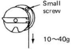 |
| Medium weight material | Knitted fabric,dress material, etc. | 15~30g | |
| Heavy weight material | Denim, wool,leather, etc. | 25~40g |
- Adjusting the stroke the tension of the thread take-up spring (Fig.13)
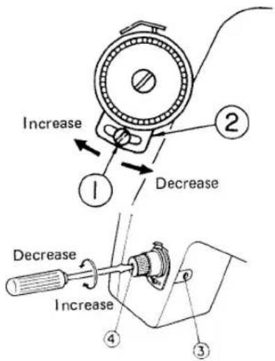
Fig. 13
Loosen the setscrew ① below the thread tension dial. Then if you shift the adjusting plate ② to the left, the amount of stroke will increase; while if you shift it to the right, then the amount of stroke will decrease.
In adjusting the strength of the thread take-up spring, loosen the setscrew ③ at the jaw portion of the arm. Then if you turn the thread tension shaft ④ to the right, the strength will increase; while if you turn it to the left, then the strength will decrease.
| Material | Amount of stroke | Strength |
| Thin material | Decrease; Shift the plate 2 to the right | Decrease; Turn the shaft 4 counterclockwise |
| Thick material | Increase; Shift the plate 2 to the left | Increase; Turn the shaft 4 clockwise |
Since this machine is adjusted in accordance with the standard, you should readjust it only when cloth shrinkage or stitch skipping has occurred depending on the kind of the thread or material.
14. Adjusting the stitch length (Fig.14)
The feed mechanism of this machine may be operated in either direction, forward or reverse, by means of the stitch adjusting lever (feed reverse lever) ①.
In adjusting the stitch length, turn the dial ② to set it at the index ③ marked over the dial. If you keep the lever ① in its highest position, the machine will operate forward with the numerically indicated stitch length; while if you let down the lever, then the machine will operate reversely with the same stitch length. If you release the lever, it will return to its original position to allow the forward operation.
When the dial is adjusted to the numeral 5, maximum stitch length may be obtained. Meanwhile, when the dial is adjusted to 0, the needle would move up and down at the same point to prevent the material from advancing and the lever from moving up and down.
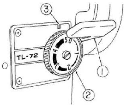
Fig. 14
(Note) For turning the dial in the direction toward smaller number (clockwise), turn it while lowering the lever to the horizontal position, and the dial will be turned easily.
15. Pressure of the presser foot
In adjusting the pressure of the presser foot, turn the presser foot adjusting screw (Fig.4 A) on the top surface of the machine head. For increasing the pressure, turn the screw clockwise; for decreasing it, turn the screw counterclockwise. Since the pressure of the presser foot may be sufficient, if it can prevent the material from following up the needle and advance the material together with the feed properly, so you need not to make it unduly high.
16. Height of the feed dog (Fig.15)
In sewing thin material, unduly protruding feed dog may crumple or bite the cloth to damage it. On the other hand, too low feed dog may not be able to advance the material, so that the height of the feed dog portion above the surface of the needle plate should be adjusted properly. In adjusting this, remove the belt, tilt the machine head backward and loosen the screw ② of the feed crank ①. Then the feed dog will move up and down freely, so adjust its height to the desired level.
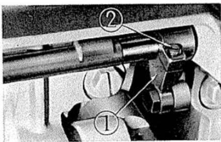
Fig. 15
17. Mounting and removing the sewing hook (Figs.16, 17 and 18)
Remove the needle, slide plate and bobbin case. Loosen the sewing hook positioning setscrew ① to remove the finger ②. Then loosen the three hook setscrews ③ and turn the hand wheel toward you until the feed bar ④ gets to its highest position.
Thus the sewing hook ⑤ may be removed by rotating it with your hand, positioning the bobbin case holder ⑥ as shown in Fig.17, and then drawing out the sewing hook.
In mounting the sewing hook, plug it onto the hook driving shaft with the relation between the positions of the sewing hook and the bobbin case holder ⑥ maintained as shown in Fig.17.
After the hook is fitted to the hook driving shaft, rotate the bobbin case holder until the groove ⑦ thereon comes on the top position, fit the bobbin case holder rotation stop into the said groove, and tighten it with the screw ①.
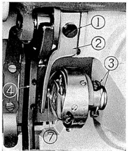
Fig. 16
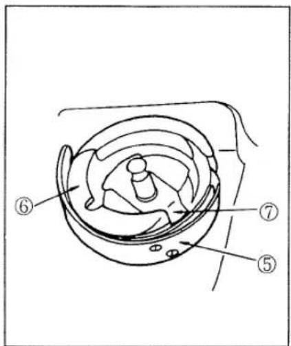
Fig. 17
Thereafter, fix the needle and match the timing of the sewing hook with that of the needle as shown in Fig.18 and fix the sewing hook in such a position.
18. Relation between the needle and the hook point (Figs.18, 19 and 20)
In order to provide the optimal sewing condition, the relative positions of the needle and the sewing hook point should be in accordance with the prescribed relationship. Namely, the point of the sewing hook should coincide with the center line of the needle at the point where the needle is positioned 2mm above the lowest point as shown in Fig.18, when the distance between the hook point and the upper end of the needle eye should be 1.6mm.
The needle bar has two engraved lines and their position relative to the sewing hook may be determined by aligning the engraved lines with the bottom surface of the needle bar bushing.
First, loosen the hook clamp screw to put the hook and the hook shaft in a free-moving condition, and, while fixing the hook in the threading position with your hand, turn the hand wheel until the needle gets to its lowest position.
At this position, determine the height of the needle bar by loosening the needle bar clamping screw ③ so as to bring the upper line ① on the needle bar in alignment with the bottom surface of the needle bar bushing ②.
Subsequently, further turn the hand wheel toward you to bring the lower line ④ on the needle bar in alignment with the bottom surface of the needle bar bushing ②, rotate the hook at this position, and fix the hook onto the hook driving shaft so that the hook point is in alignment with the center of the needle.
At that time, remove the two throat plate screws, remove the throat plate, shift the sewing hook in the axial direction of the hook shaft so that the clearance between the needle and the hook point becomes 0.05\~0.1mm, and fix the sewing hook.
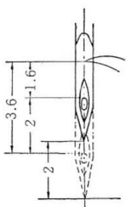
Fig. 18
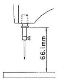
Fig. 20
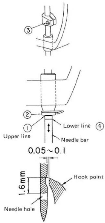
Fig. 19
Thus the relative positions of the needle bar and the sewing hook may be determined easily and correctly by the above twice adjustment.
As for the position of the needle bar bushing, the standard height of the bottom surface thereof above the top surface of the throat plate is 66.1mm (needle; DB×1) as shown in Fig.20.
19. Spool stand (Fig.21)
The spool stand of this sewing machine may be widely used for taking up cone or spools from the large industry-use thread (up to the maximum diameter of 80mm) to the small home-use thread, and it can provide high efficiency and convenience. Further, the thread guide can be stored compactly behind the machine head by only turning it with light force, and, in operation, it may be located at the proper place by only lifting it upward softly. Any trouble such as thread breakage will be eliminated by the cap which prevents the needle thread from twisting about the thread guide pin or from being caught by the flange of the spool.

Fig. 21
III. INSTALLING THE OVERHEAD LIGHT
In installing the home-use machine lamp (option at extra cost) on this sewing machine, carry out the following procedure (Figs.22 and 23)
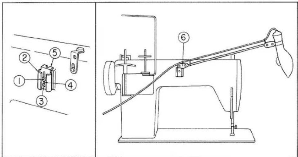
Fig. 22
Fig. 23
First, loosen by five or six revolutions the screw ① which is attached to the boss on the rear of the machine head, shift it into the round hole ③ in the lamp mounting frame ②, slide it within the slot ④ until the stopper portion ⑤ hits against the end surface of the boss, and in that position, tighten the screw ①. Then insert the lamp prong ⑥ into the lamp mounting frame ② and adjust the angle of the lamp so as to provide effective lighting as shown in Fig.23.
IV. CAUSES OF TROUBLE
1. Skip stitches
a. The needle is bent or its point is blunted.
b. The needle is not properly inserted into the needle bar.
c. The relative positions of the needle and the sewing hook are not correct.
d. The amount of swing of the thread take-up spring is too much.
2. Thread breakage
1) Where the needle thread is broken.
a. Threading procedure is wrong, or the thread tension is too strong or too weak.
b. The needle is bent or its point is blunted; the size of the thread is not compatible with that of the needle.
c. The tension of the thread take-up spring is too strong.
2) Where the bobbin thread is broken.
a. The thread tension is too strong.
b. The bobbin case spring rubs to form worn channels.
c. The thread hole in the throat plate is flawed.
3. Needle breakage
a. The needle is bent or wrongly attached.
b. The needle hits against the throat plate or the presser foot.
4. Wrinkles formed on stitches
a. The presser foot applies too much pressure against the material.
b. The tension of the needle thread is not compatible with that of the bobbin thread, or such tension is too strong.
c. The amount of swing of the thread take-up spring is too much.
5. Faulty stitch condition
a. The tension of the needle thread is not compatible with that of the bobbin thread.
b. The amount of swing of the thread take-up spring is improper, or its tension is insufficient.
- MACHINE FRAME & MISCELLANEOUS COVER COMPONENTS
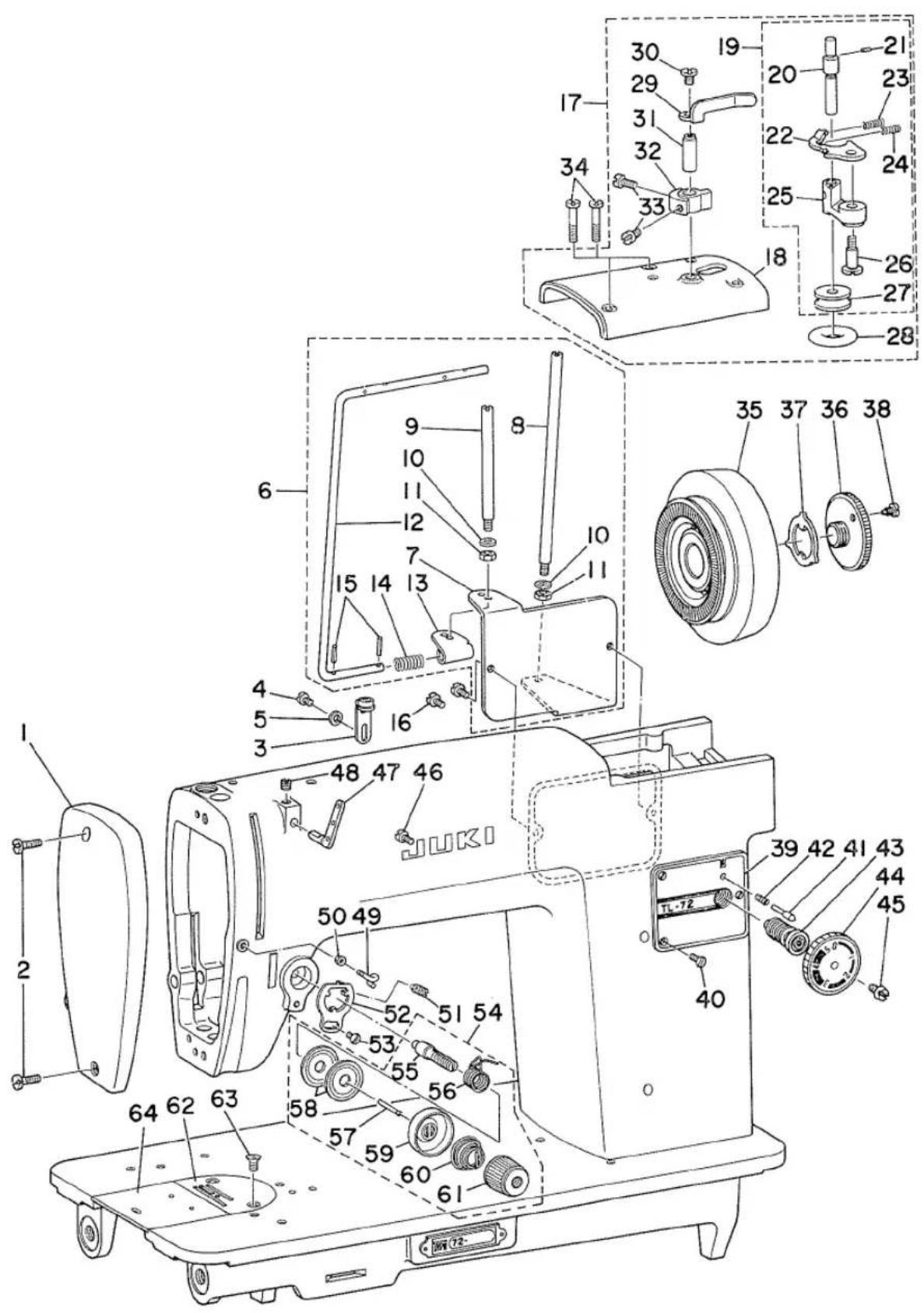
- MACHINE FRAME & MISCELLANEOUS COVER COMPONENTS
| Ref. No. | Note | Part No. | Description | E.C. | Amt. Req. |
| 1 | A3115-072-000 | Head cover | ...... | 1 | |
| 2 | SS-7091410-SL | ... Screw 9/64-40 L=13.5 | ...... | 2 | |
| 3 | A3231-957-0A0 | Thread guide frame asm. | ...... | 1 | |
| 4 | SS-7090710-SP | ... Screw 9/64-40 L=6.8 | ...... | 1 | |
| 5 | WP-0371016-SD | ... Washer 3.7 x 8.0 x 1.0 | ...... | 1 | |
| 6 | A1118-072-0A0 | Thread spool holder bracket asm. (No.7~15) | ...... | 1 | |
| 7 | A1118-072-000 | Thread spool holder bracket | ...... | (1) | |
| 8 | A1114-072-A00 | Thread spool pin (LONG) | ...... | (1) | |
| 9 | A1114-072-B00 | Thread spool pin (SHORT) | ...... | (1) | |
| 10 | WP-0460556-SD | ... Washer 4.6 x 7.5 x 0.5 | ...... | (2) | |
| 11 | NS-6110310-SP | ... Nut 11/64-40 | ...... | (2) | |
| 12 | A1115-072-000 | Needle thread guide | ...... | (1) | |
| 13 | A1116-072-000 | ... Frame | ...... | (1) | |
| 14 | A1117-072-000 | ... Spring | ...... | (1) | |
| 15 | PS-0200102-KH | ... Pin | ...... | (2) | |
| 16 | SS-7090710-SP | Thread spool holder bracket screw | ...... | 2 | |
| 17 | A1135-072-0A0 | Top cover asm. (No.18~33) | ...... | 1 | |
| 18 | A1135-072-000 | Top cover | ...... | (1) | |
| 19 | A3204-072-0A0 | Thread winder asm. (No.20~27) | ...... | (1) | |
| 20 | A3212-072-000 | Thread winder shaft | ...... | (1) | |
| 21 | A3213-072-000 | Bobbin stopper pin | ...... | (1) | |
| 22 | A3221-072-000 | Thread winder installing plate | ...... | (1) | |
| 23 | A3222-958-000 | ... Spring | ...... | (1) | |
| 24 | A3208-958-000 | ... Spring | ...... | (1) | |
| 25 | A3204-072-000 | Thread winder shaft base | ...... | (1) | |
| 26 | A3205-072-000 | ... Hinge screw | ...... | (1) | |
| 27 | A3214-062-000 | Thread winder pulley | ...... | (1) | |
| 28 | A3216-001-00A | Rubber ring | ...... | (1) | |
| 29 | A3217-072-000 | Bobbin presser | ...... | (1) | |
| 30 | A1723-957-000 | ... Screw | ...... | (1) | |
| 31 | A3218-072-000 | ... Shaft | ...... | (1) | |
| 32 | A3219-072-000 | Thread winder stop latch adjusting base | ...... | (1) | |
| 33 | SS-6111010-SP | ... Screw 11/64-40 L=9.5 | ...... | (2) | |
| 34 | SS-7091510-SA | Top cover screw 9/64-40 L=15.0 | ...... | 2 | |
| 35 | A1227-072-000 | Hand wheel | ...... | 1 | |
| 36 | A1230-001-000 | Stop-motion screw | ...... | 1 | |
| 37 | A1231-001-000 | ... Washer | ...... | 1 | |
| 38 | A1232-001-000 | ... Screw | ...... | 1 | |
| 39 | A1630-072-000 | Decoration panel | ...... | 1 | |
| 40 | SS-2090711-SL | ... Screw | ...... | 3 | |
| 41 | A1147-072-000 | Feed regulating pin | ...... | 1 | |
| 42 | B1148-012-000 | ... Spring | ...... | 1 | |
| 43 | A1652-007-000 | ... Screw | ...... | 1 | |
| 44 | A1647-072-0A0 | Stitch dial asm. | ...... | 1 | |
| 45 | SS-6121050-SP | ... Screw 3/16-28 L=9.5 | ...... | 1 | |
| 46 | SS-7090710-SP | Overhead light screw 9/64-40 L=6.8 | ...... | 1 | |
| 47 | B1128-522-000 | Three-hole thread eyelet | ...... | 1 | |
| 48 | SS-8110510-SP | ... Screw 11/64-40 L=5.0 | ...... | 1 | |
| 49 | B3114-761-000 | Take-up thread guide | ...... | 1 | |
| 50 | NS-6060350-SP | ... Nut 3/32-56 | ...... | 1 | |
| 51 | SS-8111251-SP | Thread tension screw 11/64-40 L=12.0 | ...... | 1 | |
| 52 | A3111-072-000 | Take-up spring adjusting plate | ...... | 1 | |
| 53 | SS-3090510-SL | ... Screw 9/64-40 L=5.0 | ...... | 1 | |
| 54 | A3122-072-0A0 | Thread tension asm. (No.57~63) | ...... | 1 | |
| 55 | B3122-027-000 | Thread tension post | ...... | (1) | |
| 56 | A3128-072-000 | Take-up spring | ...... | (1) | |
| 57 | A3127-072-000 | Tension release pin | ...... | (1) | |
| 58 | B3126-012-000 | Thread tension disc | ...... | (2) | |
| 59 | A3132-072-000 | ... Presser | ...... | (1) | |
| 60 | B3129-012-A00 | ... Spring (A) | ...... | (1) | |
| 61 | A3124-072-000 | ... Knob | ...... | (1) | |
| 62 | A1109-007-000 | Throat plate | ...... | 1 | |
| 63 | SS-2110910-SL | ... Screw 11/64-40 L=8.5 | ...... | 2 | |
| 64 | A1110-007-0A0 | Bed slide asm. | ...... | 1 |
- MAIN SHAFT & NEEDLE BAR & UPRIGHT SHAFT & HOOK DRIVING SHAFT COMPONENTS
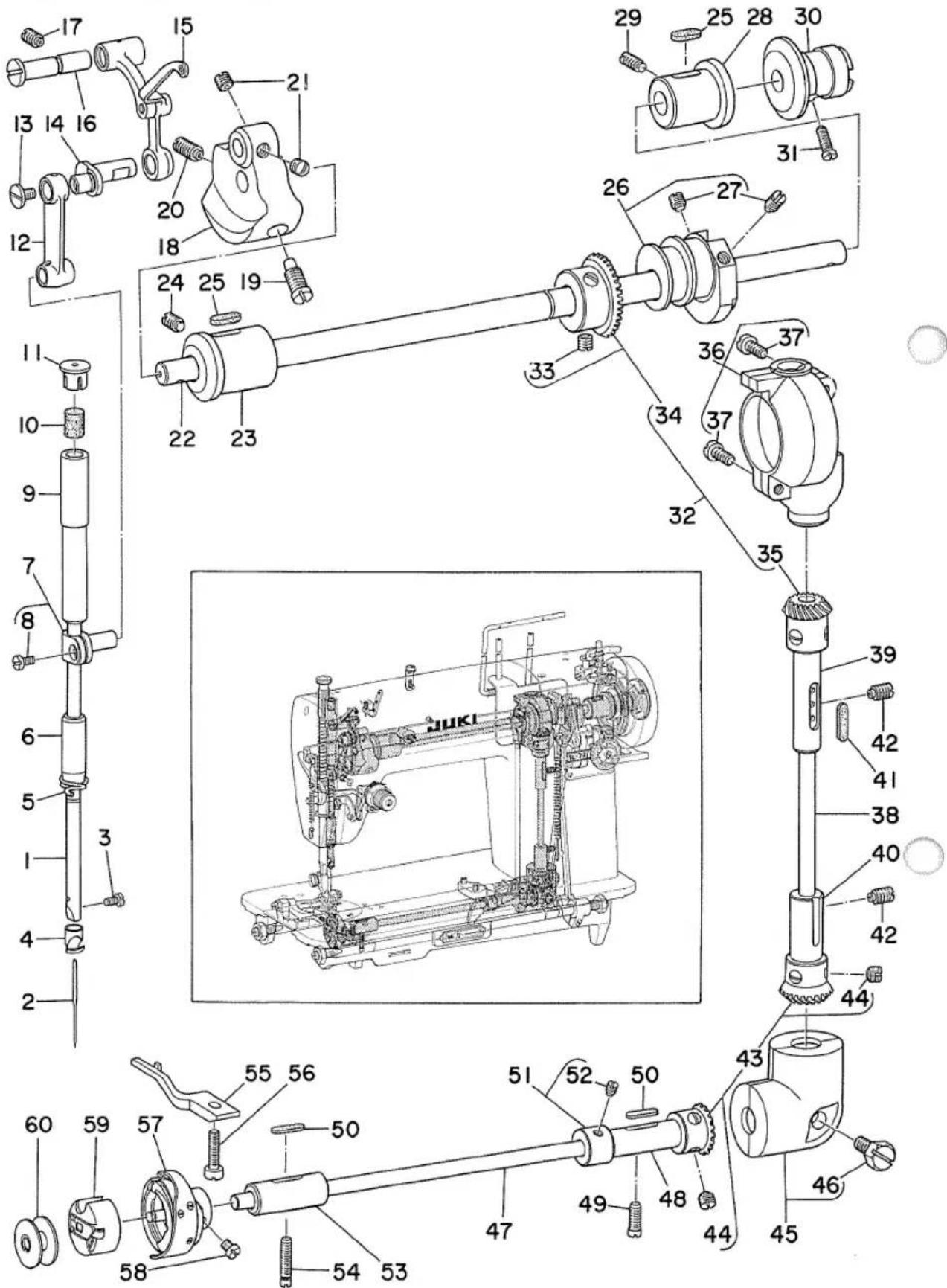
- MAIN SHAFT & NEEDLE BAR & UPRIGHT SHAFT & HOOK DRIVING SHAFT COMPONENTS
| Ref. No. | Note | Part No. | Description | E.C. | Amt. Req. |
| 1 | A1401-072-A00 | Needle bar | ...... | 1 | |
| 2 | MDB-10081400 | Needle (DB x #14) | ...... | 1 | |
| 3 | SS-7080510-SP | ... Screw 1/8-44 L=4.5 | ...... | 1 | |
| 4 | A1418-072-000 | Needle bar thread guide | ...... | 1 | |
| 5 | B1419-155-000 | Needle bar thread guide | ...... | 1 | |
| 6 | A1403-072-000 | Needle bar bushing, lower | ...... | 1 | |
| 7 | A1411-007-0A0 | Needle bar connection asm. | ...... | 1 | |
| 8 | SS-6090650-SP | ... Screw 9/64-40 L=6.0 | ...... | (1) | |
| 9 | A1402-072-000 | Needle bar bushing, upper | ...... | 1 | |
| 10 | A1404-072-000 | ... Felt | ...... | 1 | |
| 11 | B1405-012-000 | ... Rubber plug | ...... | 1 | |
| 12 | A1408-072-000 | Needle bar crank rod | ...... | 1 | |
| 13 | A1219-907-000 | Thread take-up crank screw, left | ...... | 1 | |
| 14 | A1209-072-000 | Needle bar crank | ...... | 1 | |
| 15 | A1901-072-0A0 | Thread take-up lever asm. | ...... | 1 | |
| 16 | A1902-072-000 | Thread take-up presser shaft | ...... | 1 | |
| 17 | SS-8151150-SP | ... Screw 15/64-28 L=10.5 | ...... | 1 | |
| 18 | A1206-072-000 | Counterweight asm. | ...... | 1 | |
| 19 | SS-7681650-TP | ... Screw (A) 9/32-28 L=16.0 | ...... | 1 | |
| 20 | SS-8681650-TP | ... Screw (B) 9/32-28 L=16.0 | ...... | 1 | |
| 21 | SS-8660530-TP | Needle bar crank screw 1/4-40 L=4.5 | ...... | 2 | |
| 22 | A1201-072-000 | Main shaft | ...... | 1 | |
| 23 | A1202-072-000 | ... Bushing, front | ...... | 1 | |
| 24 | SS-8151150-SP | ... Screw 15/64-28 L=10.5 | ...... | 1 | |
| 25 | A1203-007-000 | ... Felt | ...... | 2 | |
| 26 | A1210-007-0A0-A | Feed driving cam asm. | ...... | 1 | |
| 27 | SS-8151150-SP | ... Screw 15/64-28 L=10.5 | ...... | (2) | |
| 28 | A1204-007-000 | Main shaft bushing, rear | ...... | 1 | |
| 29 | SS-8151550-SP | ... Screw 15/64-28 L=10.5 | ...... | 1 | |
| 30 | A1229-007-000 | Hand wheel bushing | ...... | 1 | |
| 31 | SS-7111260-SP | ... Screw 11/64-40 L=12.0 | ...... | 1 | |
| 32 | A1305-007-0B0 | Gear & pinion asm., upper (No.32~34) | ...... | 1 | |
| 33 | SS-8660610-SP | ... Screw 1/4-40 L=6.0 | ...... | (4) | |
| 34 | A1305-007-0A0 | Gear asm. | ...... | (1) | |
| 35 | A1306-007-0A0 | Pinion asm. | ...... | (1) | |
| 36 | A1308-007-0A0 | Gear case asm., upper | ...... | 1 | |
| 37 | SS-6121210-SP | ... Screw 3/16-28 L=12.0 | ...... | (2) | |
| 38 | A1301-007-000 | Upright shaft | ...... | 1 | |
| 39 | A1302-007-000 | ... Bushing, upper | ...... | 1 | |
| 40 | A1303-007-000 | ... Bushing, lower | ...... | 1 | |
| 41 | B1304-012-A00 | ... Bushing felt A | ...... | 1 | |
| 42 | SS-8151150-SP | ... Screw 15/64-28 L=10.5 | ...... | 2 | |
| 43 | A1307-007-0A0 | Gear asm. | ...... | 1 | |
| 44 | SS-8660610-SP | ... Screw 1/4-40 L=6.0 | ...... | (4) | |
| 45 | A1309-007-0A0 | Gear case asm., lower | ...... | 1 | |
| 46 | SS-9181520-SP | ... Screw 9/32-20 L=15.0 | ...... | (1) | |
| 47 | A1801-007-000 | Hook driving shaft | ...... | 1 | |
| 48 | A1804-007-000 | ... Bushing, rear | ...... | 1 | |
| 49 | SS-6111110-SP | ... Screw 11/64-40 L=11.0 | ...... | 1 | |
| 50 | B1806-038-000 | Bushing felt | ...... | 2 | |
| 51 | CS-0721210-SH | Thrust collar asm. | ...... | 1 | |
| 52 | SS-8110510-SP | ... Screw 11/64-40 L=5.0 | ...... | (2) | |
| 53 | A1802-007-000 | Hook driving shaft bushing, front | ...... | 1 | |
| 54 | SS-6111740-SP | ... Screw 11/64-40 L=17.0 | ...... | 1 | |
| 55 | B1835-012-000 | Bobbin case holder positioning finger | ...... | 1 | |
| 56 | SS-61111620-SP | ... Screw 11/64-40 L=16.0 | ...... | 1 | |
| 57 | B1830-009-0A0 | Hook asm. | ...... | 1 | |
| 58 | SS-6110560-TP | ... Screw | ...... | (3) | |
| 59 | B1837-012-0A0 | Bobbin case asm. | ...... | 1 | |
| 60 | A9117-007-000 | Bobbin | ...... | 1 |


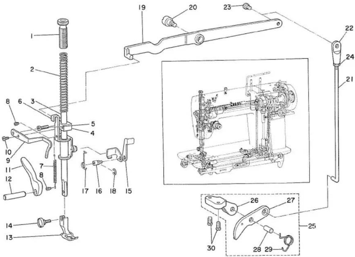
- PRESSER BAR & KNEE LIFTER COMPONENTS
| Ref. No. | Note | Part No. | Description | E.C. | Amt. Req. |
| 1 | B1509-012-000 | Presser spring regulator | ...... | 1 | |
| 2 | A1505-072-000 | Presser spring | ...... | 1 | |
| 3 | A1501-072-000 | Presser bar | ...... | 1 | |
| 4 | B1507-552-000 | Presser bar guide bracket | ...... | 1 | |
| 5 | SS-7111410-SP | ... Screw 11/64-40 L=14.0 | ...... | (1) | |
| 6 | A1509-072-0A0 | Hand lifter lever connecting link | ...... | 1 | |
| 7 | A1515-072-000 | ... Spring | ...... | 1 | |
| 8 | A1516-072-000 | ... Suspension stud | ...... | 2 | |
| 9 | B1521-552-000 | Presser bar clamp thread guide | ...... | 1 | |
| 10 | SS-6090650-SP | ... Screw 9/64-40 L=6.0 | ...... | 1 | |
| 11 | A1512-072-000 | Hand lifter lever | ...... | 1 | |
| 12 | A1513-072-000 | ... Shaft | ...... | 1 | |
| 13 | B1524-072-0A0 | Hinged presser foot asm. | ...... | 1 | |
| 14 | A1132-025-000 | ... Screw | ...... | 1 | |
| 15 | A1517-072-000 | Tension release plate | ...... | 1 | |
| 16 | A1518-072-000 | ... Stud | ...... | 1 | |
| 17 | A1519-072-000 | ... Spring | ...... | 1 | |
| 18 | RE-0400000-K0 | ... Snap ring | ...... | 1 | |
| 19 | A3406-072-0A0 | Knee lifter lever asm. | ...... | 1 | |
| 20 | A3407-007-000 | ... Hinge pin | ...... | 1 | |
| 21 | A3413-007-000 | Knee lifter lever connecting rod | ...... | 1 | |
| 22 | A3416-007-000 | Swivel | ...... | 1 | |
| 23 | SD-0600401-SD | ... Hinge screw D=6.00 H=4.0 | ...... | 1 | |
| 24 | NS-6620310-SP | ... Nut 3/16-32 | ...... | 1 | |
| 25 | A3401-007-0A0 | Bell crank bracket asm. (No.26~29) | ...... | 1 | |
| 26 | A3401-007-000 | Bell crank bracket | ...... | (1) | |
| 27 | B3402-012-000 | Bell crank | ...... | (1) | |
| 28 | B3403-012-000 | ... Pin | ...... | (1) | |
| 29 | A3404-007-000 | ... Spring | ...... | (1) | |
| 30 | SS-7120910-SP | ... Screw 3/16-28 L=9.0 | ...... | 2 |
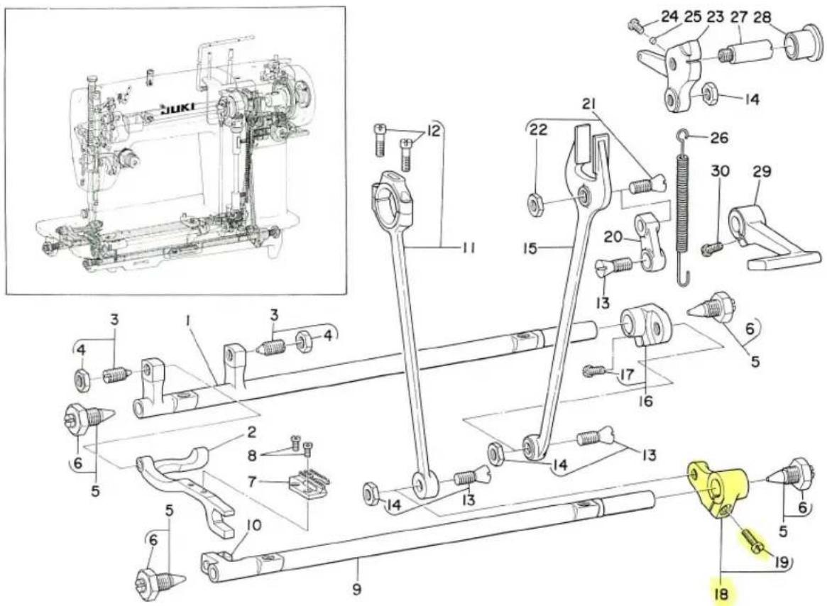
- FEED REGULATOR COMPONENTS
| Ref. No. | Note | Part No. | Description | E.C. | Amt. Req. |
| 1 | A1601-007-000 | Feed rocker shaft | ...... | 1 | |
| 2 | A1602-007-000 | Feed bar | ...... | 1 | |
| 3 | A1603-007-0A0 | ... Center screw asm. | ...... | 2 | |
| 4 | NS-6680330-SP | ... Nut 9/32-28 | ...... | (2) | |
| 5 | B1113-012-0A0 | Center screw asm. | ...... | 4 | |
| 6 | NS-6740510-SP | ... Nut 3/8-28 | ...... | (4) | |
| 7 | A1613-007-000 | Feed dog | ...... | 1 | |
| 8 | SS-4080610-SP | ... Screw 1/8-44 L=6.4 | ...... | 2 | |
| 9 | A1702-007-000 | Feed driving shaft | ...... | 1 | |
| 10 | A1710-001-0A0 | Feed driving shaft crank asm. | ...... | 1 | |
| 11 | A1701-007-0A0-A | Feed driving shaft connecting rod asm. | ...... | 1 | |
| 12 | SS-6121610-SP | ... Screw 3/16-28 L=15.5 | ...... | (2) | |
| 13 | A1703-001-0A0 | Taper screw asm. | ...... | 3 | |
| 14 | NS-6680420-SP | ... Nut 9/32-28 | ...... | (3) | |
| 15 | A1614-007-000 | Pitman | ...... | 1 | |
| 16 | A1612-007-0A0 | Feed rocker shaft crank asm. | ...... | 1 | |
| 17 | SS-7111410-TP | ... Screw 11/64-40 L=14.0 | ...... | (1) | |
| 18 | A1706-007-0A0 | Feed driving shaft crank asm. | ...... | 1 | |
| 19 | SS-7111410-TP | ... Screw 11/64-40 L=14.0 | ...... | (1) | |
| 20 | A1619-007-000 | Feed regulator connecting link | ...... | 1 | |
| 21 | A1703-007-0A0 | Taper screw asm. | ...... | 1 | |
| 22 | NS-6680330-SP | ... Nut 9/32-28 | ...... | (1) | |
| 23 | A1622-072-000 | Feed regulator | ...... | 1 | |
| 24 | SS-7110710-SP | ... Screw 11/64-40 L=7.0 | ...... | 1 | |
| 25 | A1627-007-000 | ... Pin | ...... | 1 | |
| 26 | A1683-072-000 | ... Spring | ...... | 1 | |
| 27 | A1625-072-000 | ... Hinge pin | ...... | 1 | |
| 28 | A1626-007-000 | ... Bushing | ...... | 1 | |
| 29 | A1628-072-000 | Stitch adjusting lever | ...... | 1 | |
| 30 | SS-7111410-TP | ... Screw 11/64-40 L=14.0 | ...... | 1 |
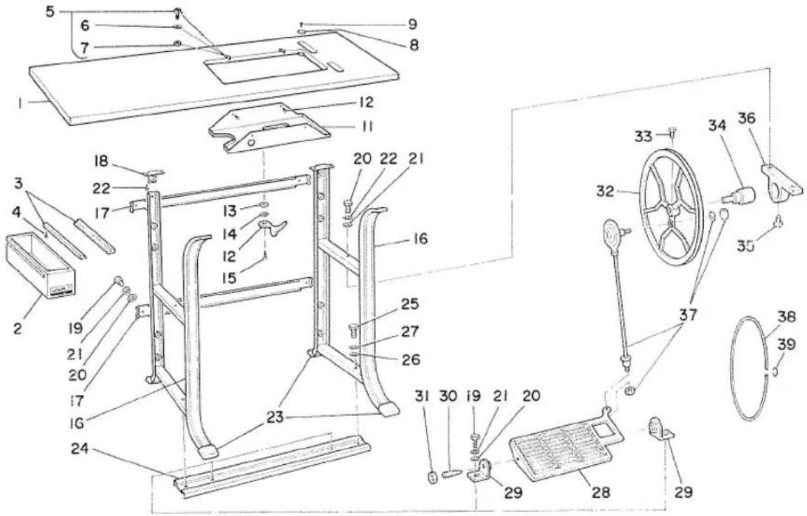
- TABLE COMPONENTS
| Ref. No. | Note | Part No. | Description | E.C. | Amt. Req. |
| 1 | A8201-072-000 | Table | 1 |
| 2 | A8203-007-0A0 | Drawer | 1 |
| 3 | A8204-007-000 | ... Holder | 2 |
| 4 | SK-1211000-SC | ... Wood screw | 4 |
| 5 | A8213-007-AA0 | Hinge asm. | 2 |
| 6 | WP-0850002-SC | ... Washer | (2) |
| 7 | NS-6680410-SN | ... Nut 9/32-28 | (2) |
| 8 | B8207-012-000 | Rubber cushion A | 4 |
| 9 | B8210-012-000 | ... Stud | 4 |
| 10 | A8217-007-000 | Drip pan | 1 |
| 11 | SK-1271300-SC | ... Wood screw | 4 |
| 12 | A8206-007-000 | Position plate | 1 |
| 13 | A8211-007-000 | ... Waved washer | 1 |
| 14 | WP-0612056-SD | ... Washer | 1 |
| 15 | SK-3452000-SC | ... Wood screw | 1 |
| 16 | A8101-072-000-A | Stands, outside | 2 |
| 17 | A8102-072-000 | Stands, inside | 2 |
| 18 | A8144-072-000 | Table installing plate | 2 |
| 19 | SM-9082023-SE | Stand screw M8 x 1.25 L=20.0 | 10 |
| 20 | WP-0851846-SC | ... Washer | 10 |
| 21 | WS-0861410-KR | ... Spring washer | 10 |
| 22 | SK-3552500-SC | ... Wood screw | 6 |
| 23 | A8143-072-000 | Stands cover | 4 |
| 24 | A8103-072-000 | Support, lower | 1 |
| 25 | SM-9084503-SE | ... Screw M8 x 1.0 L=45.0 | 2 |
| 26 | WP-0851846-SC | ... Washer | 2 |
| 27 | WS-0861410-KR | ... Spring washer | 2 |
| 28 | A8105-007-00A | Pedal | 1 |
| 29 | A8104-072-000 | ... Retainer | 2 |
| 30 | A8107-011-000 | Stands center screw | 2 |
| 31 | NS-6280630-SN | ... Nut 7/16-16 | 2 |
| 32 | A8106-072-000 | Belt pulley | 1 |
| 33 | SM-9061403-SE | ... Screw M6 x 1.0 L=14.0 | 1 |
| 34 | A8109-072-0A0 | ... Hinge pin asm. | 1 |
| 35 | SM-9061403-SE | ... Screw M6 x 1.0 L=14.0 | 1 |
| 36 | A8108-072-000 | ... Retainer | 1 |
| 37 | A8130-072-0A0 | Pitman asm. | 1 |
| 38 | A8214-007-000 | Leather belt (FOR TREADLE TYPE) | 1 |
| 39 | A7125-007-000 | Belt fastener | 1 |
- KNEE LIFTER & MOTOR COMPONENTS
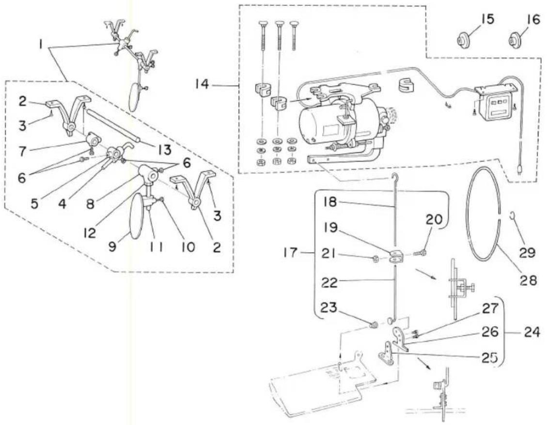
| Ref. No. | Note | Part No. | Description | E.C. | Amt. Req. |
1 B3418-012-0A0 Knee lifter asm. 1
2 B3422-012-000 Kneo press rod retainer (2)
3 SK-1352500-SC Wood screw (4)
4 B3423-012-000 Bell crank lifter rod ..... (1)
5 B3424-012-000 . . . Joint (1)
6 SS-9201510-SN . . . Screw 5/16-18 L=15.0 (4)
7 B3425-012-000 Knee lifter rotation stopper (1)
8 B3420-012-000 Knee lifter plate rod joint (1)
9 B3418-012-000 Knee press plate (1)
10 SM-9081620-SE . . . Screw M8 x 1.25 L=16.0 (1)
11 B3419-012-000 Knee lifter plate rod (1)
12 NM-6080721-SE Nut M8 x 1.25 (1)
13 B3421-012-000 Knee press rod (1)
14 MSL-2100010S Motor 1/8 HP asm. 1
15 MTK-PV050000 Motor pulley (FOR 50Hz) 1
16 MTK-PV040000 Motor pulley (FOR 60Hz) 1
17 B7115-012-0A0 Clutch connecting rod (No.18\~23) 1
18 B7115-012-000 Connecting rod, upper (1)
19 B7114-012-000 Connecting rod joint (1)
20 SM-9081423-SE . . . Screw M8 x 1.25 L=14.0 (1)
21 NM-6080721-SE . . . Nut M8 x 1.25 (1)
22 B7116-012-000 Connecting rod, lower (1)
23 B7133-012-000 . . . Spring (1)
24 A7130-072-0A0 Connecting plate asm. 1
25 A7130-072-000 Connecting plate (1)
26 D3163-555-B00 . . . Thrust plate (1)
27 SS-7110820-SP . . . Screw 11/64-40 L=7.5 (2)
28 MTJ-SA0700L0 Leather belt (FOR MOTOR OPERATED TYPE) 1
29 A7125-007-000 Belt fastener 1
MEMO

natural_image
Two simple circular shapes drawn on a plain background, no text or symbols present.