
ACCS2004 - Okategoriserad APC - Gratis bruksanvisning och manual
Hitta enhetens manual gratis ACCS2004 APC i PDF-format.


Användarfrågor om ACCS2004 APC
0 fråga om denna apparat. Svara på dem du kan eller ställ din egen.
Ställ en ny fråga om denna apparat
Ladda ner instruktionerna för din Okategoriserad i PDF-format gratis! Hitta din manual ACCS2004 - APC och ta tillbaka ditt elektroniska enhet i hand. På denna sida publiceras alla dokument som behövs för att använda din enhet. ACCS2004 av märket APC.
BRUKSANVISNING ACCS2004 APC
Schneider Electric
Air Containment Adapter Kits (300mm) Installation
ACCS2004 - ACCS2005 - ACCS2006 - ACCS2007
natural_image
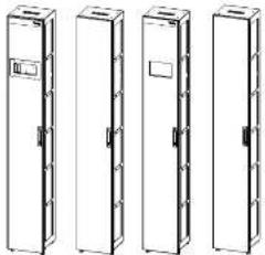
Four identical line drawings of vertical rectangular cabinets or storage units, no text or symbols present.ACCS2004 and ACCS2005 compatible with ACRD101, ACRD301
ACCS2006 and ACCS2007 compatible with ERC301CW

Recycle or dispose of the packaging materials appropriately.
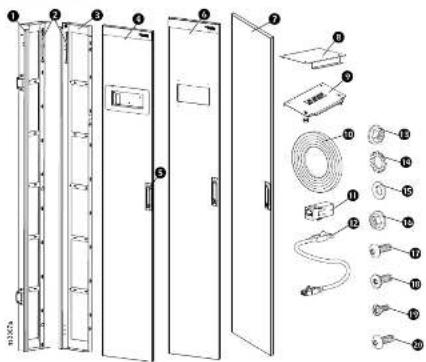
Inventory
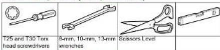
Tools Required (not provided)
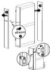
Prepare the Cooling Unit
Each kit contains the parts for one (front or rear) installation.
Refer to your cooling unit's manual for instructions for the below tasks.
-
Disconnect the cable from the display interface.
-
Remove the front and rear doors from the cooling unit.
-
Remove the hinges from the cooling unit, if applicable.
NOTE: 1. In existing rows of racks, the joining brackets securing the racks and cooling units together on the front side are not removed.
- All racks in the row must be level and secured together with the joining brackets (at the front) prior to installing the air containment adapters.
IMPORTANT SAFETY INSTRUCTIONS
▲ CAUTION
HEAVY EQUIPMENT HAZARD
- The kit components are heavy. Use caution when lifting. - Wear appropriate personal protective equipment (PPE) and follow safe work practices
Failure to follow these instructions can result in injury or equipment damage.
Receiving
Inspect the Equipment
Carefully inspect the shipment for visible signs of damage. If you detect shipping damage, contact your shipping company immediately and Schneider Electric Customer Support at www.se.com.
Storage
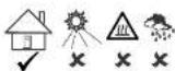
These components should be stored indoors and out of the weather. Do not allow the panels to be exposed to the elements.
NOTICE
- Leaving the kit components uncovered and exposed to the elements will cause damage and void the factory warranty. - Wipe the panels with a damp cloth to clean. Do not use solvents or abrasive cleaners.
| Item | Description Qty | |
| 1 | Adapter side frame with door hinges | 1 |
| 2 | Grounding Wire1 inside adapter door, 1 on inside rear of hinge side adapter frame. | 2 |
| 3 | Adapter door handle side frame 42U | 1 |
| 4 | ACCS2004 Door | 1 |
| 5 | Door Handle (installed on doors) | 2 |
| 6 | ACCS2006 Door | 1 |
| 7 | Door (Rear adapter kits) | 1 |
| 8 | Adapter top | 1 |
| 9 | Adapter bottom | 1 |
| 10 | EVA foam seal 2.0 x 20 x 2000 (mm) | 1 |
| 11 | Display RJ45 connector adapter (for use with ACRD101 only) | 1 |
| 12 | Display interface connector cable (for use with ACRD101 only) | 2 |
| 13 | M6 flanged hex nut | 8 |
| 14 | Washer M6 serrated | 2 |
| 15 | Washer Nylon ID 6 PD 12 | 6 |
| 16 | M5 flanged hex nut | 1 |
| 17 | Screw M5 x 12 Pan head T30 Nylok | 6 |
| 18 | Screw M8 x 12 Flat head Nylok T30 | 4 |
| 19 | Screw M5 x 10 Pan head T25 | 3 |
| 20 | Screw M6 x 12 Pan head T30 | 1 |
10/2021
990-91538
©2021 Schneider Electric. All rights reserved.
WOW, SE, CO
Customer support and warranty/information is available at
Worldwide Customer Support
Cooling Unit Display
NOTICE
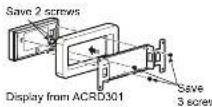
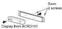
Remove the Display Interface from the Cooling Unit Door. Save the Display Interface and its mounting hardware for installation to the adapter door.
Install Air Containment Kit Mounting Screws
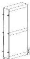
Install six (6) M6 x 12 Pan head T30 screws and six (6) nylon washers (provided) to the front and rear of the cooling unit in the holes corresponding to the mounting holes in the Air Containment frame. The screws are installed only halfway to leave room to place the Air Containment frame over the screw heads.
Assemble the Air Containment Kit
CAUTION
HEAVY EQUIPMENT HAZARD
Some of the components of the Air Containment Kit are heavy. It is recommended that two (2) people lift and move the larger parts.
Failure to follow these instructions can result in injury or equipment damage.
Frame
Insert the four (4) threaded posts on top and bottom parts through the holes at the top and bottom of the left and right frame pieces. Once the top and bottom are set into the side frames, secure them with eight (8) M6 flanged hex nuts using a 10-mm wrench.
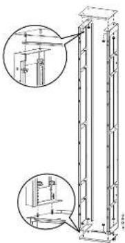
natural_image
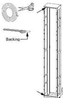
Technical line drawing of a vertical structural component with two circular insets showing internal components (no text or symbols)Apply the Gasket Material
- Cut the gasket material to size.
- Peel the backing paper from the gasket, exposing the glue.
- Apply the gasket material to the top and bottom of the frame, pressing to secure the gasket in position.
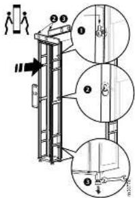
Install the Air Containment Frame
- Hang the Air Containment frame on the screws leaving the washers between the frame and the Cooling Unit.
- Tighten the six (6) M8 x 12 Pan head T30 screws to secure the air containment frame to the rack. Use a level (not provided) to make sure the frame and Cooling Unit are level.
- Lower and adjust the leveling feet of the adapter using a 13-mm wrench (not provided) while still using the level.
Attach the ground wire on the rear of the Air Containment frame to the rack in the row next to the cooling unit using one (1) M6 serrated washer and one (1) M8 x 12 pan head T30 screw (provided).
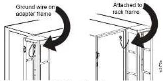
NOTE: There is a ground wire on all Air Containment frames
Install the Door
-
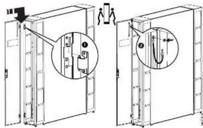
Install the door to the Air Containment frame by lifting the door until the receivers on the door are positioned above the hinge pins on the frame and then lowering the door until the receivers engage the hinge pins.
-
Attach the ground wire on the Air Containment frame to the threaded stud on the door using one (1) M6 serrated washer and one (1) M5 flanged nut provided in the hardware bag.
Install the Cooling Unit Display Interface to the Adapter Door
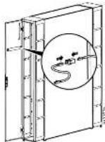
Use the hardware saved when the display was removed from the cooling unit to install the display interface in the door of the adapter. Install the cover (ACCS2004) to the door using four (4) flanged hex nuts provided.
NOTE: For ACRD101 Cooling Units, the cable extension and connector will be required. Install the cable and connector to the display cable.
Join the Air Containment Adapters
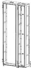
When multiple Air Containment Kits are installed in a row of racks, the adapter side frames are secured to the next side frame in the row using three (3) M5 x 10 Pan head screws provided in the hardware bag with your kit.
- Schneider Electric
- Air Containment Adapter Kits (300mm) Installation
- Prepare the Cooling Unit
- IMPORTANT SAFETY INSTRUCTIONS
- ▲ CAUTION
- Receiving
- Storage
- NOTICE
- WOW, SE, CO
- Cooling Unit Display
- Install Air Containment Kit Mounting Screws
- Assemble the Air Containment Kit
- CAUTION
- HEAVY EQUIPMENT HAZARD
- Frame
- Apply the Gasket Material
- Install the Air Containment Frame
- Install the Door
- Install the Cooling Unit Display Interface to the Adapter Door
- Join the Air Containment Adapters
Märke : APC
Modell : ACCS2004
Kategori : Okategoriserad