AC-MX-82 - Маршрутизатор AVPro Edge - Бесплатное руководство пользователя
Найдите руководство к устройству бесплатно AC-MX-82 AVPro Edge в формате PDF.


| Тип продукта | AV матричный коммутатор |
| Бренд | AVPro Edge |
| Модель | AC-MX-82 |
| Форм-фактор | Монтируемый в стойку, 1U |
| Размеры (ШxГxВ) | 482.6 x 254 x 44.5 мм |
| Вес | 3.2 кг |
| Блок питания | 100-240 В переменного тока, 50/60 Гц, внутренний |
| Потребляемая мощность | макс. 30 Вт |
| Входные порты | 8 x HDMI (4K@60 Гц) |
| Выходные порты | 2 x HDMI (4K@60 Гц) |
| Интерфейс управления | Ethernet, RS-232, ИК, передняя панель |
| Максимальное разрешение | 4K@60 Гц 4:4:4 |
| Поддержка HDCP | HDCP 2.2/1.4 |
| Поддержка аудио | Встроенное аудио, сквозной проход |
| Управление EDID | Встроенная эмуляция EDID |
| Рабочая температура | от 0°C до 40°C |
| Сертификаты безопасности | CE, FCC, RoHS |
| Гарантия | 3 года ограниченная |
Часто задаваемые вопросы - AC-MX-82 AVPro Edge
Вопросы пользователей о AC-MX-82 AVPro Edge
0 вопрос об этом устройстве. Ответьте на те, что знаете, или задайте свой.
Задать новый вопрос об этом устройстве
Скачайте инструкцию для вашего Маршрутизатор в формате PDF бесплатно! Найдите своё руководство AC-MX-82 - AVPro Edge и возьмите своё электронное устройство обратно в руки. На этой странице опубликованы все документы, необходимые для использования вашего устройства. AC-MX-82 бренда AVPro Edge.
РУКОВОДСТВО ПОЛЬЗОВАТЕЛЯ AC-MX-82 AVPro Edge
User Manual
18Gbps True 4K60 4:4:4, 8x2 Matrix & Auto Switch/AVR Bypass
AC-MX-82

INTRODUCTION 4
FEATURES 4
WHAT IN THE BOX 4
SPECIFICATIONS ....5
FRONT AND REAR PANEL OVERVIEW 6
INITIAL SETUP: WEBUI 7
ADVANCED SETUP: WEBUI INPUT SETTINGS 11
ADVANCED SETUP: WEBUI OUTPUT SETTINGS 12
ADVANCED SETUP: WEBUI EXTRACTED AUDIO OUTPUT SETTINGS 13
WEBUI: VIDEO MATRIX 14
WEBUI: I/O CONFIG - INPUT SETTINGS 15
WEBUI: I/O CONFIG - INPUT SETTINGS CONT 16
WEBUI: I/O CONFIG - OUTPUT SETTINGS 16
WEBUI: I/O CONFIG - AUDIO SETTINGS 17
WEBUI: SYSTEM - IP CONTROL 17
WEBUI: SYSTEM - ADMIN WEB INTERFACE ....18
WEBUI: SYSTEM - USER WEB INTERFACE 19
WEBUI: SYSTEM - CLOUD SERVICES 20
WEBUI: SYSTEM - FIRMWARE UPDATE CONT 21
WEBUI: SYSTEM - HARDWARE 21
WEBUI: DIAGNOSTICS - HDMI IN 22
WEBUI: DIAGNOSTICS - HDMI IN CONT 23
WEBUI: DIAGNOSTICS - HDMI OUT 24
WEBUI: CONSOLE 25
FRONT PANEL CONTROL - FUNCTIONAL MODE BUTTON 26
FRONT PANEL CONTROL - MATRIX MODE SWITCHING 26
FRONT PANEL CONTROL - DA MODE SWITCHING 26
FRONT PANEL CONTROL - AUDIO OUTPUT 27
FRONT PANEL CONTROL - EDID MANAGEMENT: 28
EDID MANAGEMENT: 29
IR CONTROL: IR REMOTE 30
RS-232 AND TCP/IP CONTROL: 31
COMMAND LIST: 32
COMMAND LIST CONTINUED: 33
EXTRACTED AUDIO: 34
BALANCED 5 PIN 2CH AND TOSLINK AUDIO PORT /SPDIF: 34
TROUBLESHOOTING 35
BANDWITH CHART 35
MAINTENANCE 36
DAMAGE REQUIRING SERVICE ....36
SUPPORT 37
WARRANTY 37
Introduction
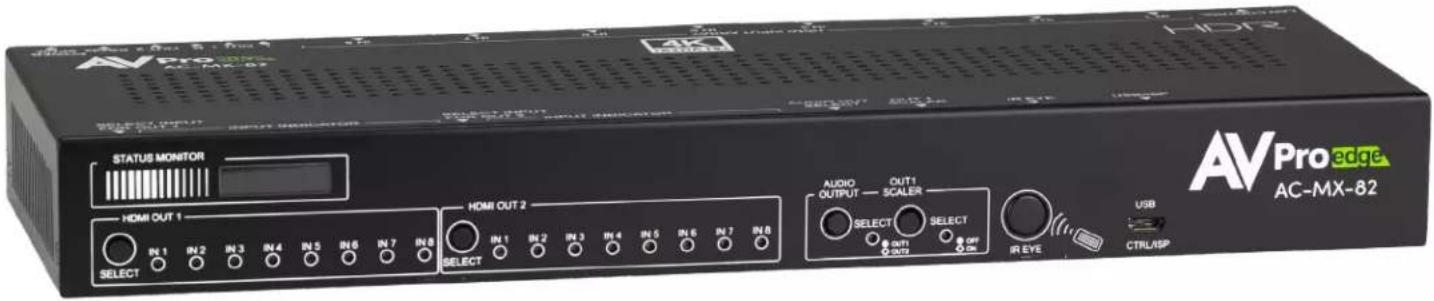
The AC-MX-82 is a 8x2 HDMI matrix switch. Supporting HDMI 2.0(a/b), HDCP 2.3 and previous, up to 4K video resolution, and up to 18Gbps bandwidth. This switch allows any source (Blu-ray, satellite receiver, game consoles, PCs, etc.) to show on any connected displays. In addition, this matrix equalizes and amplifies the output to ensure the HDMI signal will transmit through long HDMI cables without loss of quality.
The AC-MX-82 is ideal for bypassing AVRs that do not support full 18Gbps. Instead of bottlenecking video quality through a legacy audio device that can't handle 18Gbps. Integrators can run down-scaled video to a legacy audio device and send uncompressed HDMI to the display. Audio remains untouched on a down-scaled output, making it an ideal component for systems where high bit rate audio is critical.
Features
• HDMI 2.0(a/b)
• 18Gbps Bandwidth Support
• 4K60 4:4:4 Support
• Full HDR Support (HDR 10 & 12 Bit)
• Dolby Vision, HDR10+ and HLG Support
• HDCP 2.3 (and all earlier versions supported)
• 4K > 1080p Down Scaler (Out 1)
- Perfect AVR Bypass deliver 18Gbps to Display and uncompressed audio to AVR
• Advanced EDID Management
• IR, RS-232 and LAN Control Options
• Digital Toslink Out (7CH PCM, DD, DTS)
• Balanced Analog Out (2CH PCM)
• Down-scaling mode for mixed systems
• Driver Support for Crestron, C4, RTI, ELAN and more
• Extracted Audio Supports DD+, DTS Master Audio on Toslink
• Extracted Audio bound to output 1 or 2
Whats in the box
• AC-MX-82 (Matrix Switch)
• 12V/2A Locking Power Supply
• 1 x IR Remote Control
• 1 x 3 Pin Terminal Connector (For RS232)
- Mounting Brackets
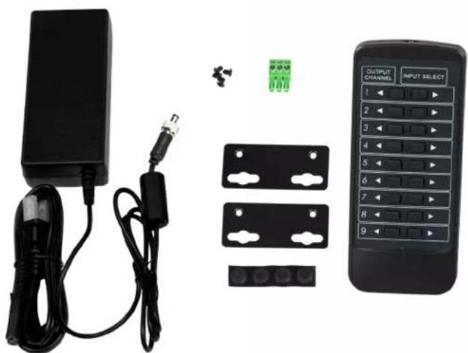
natural_image
Product photo of a remote control device with attached cable, connector, and terminal blocks (no visible text or symbols)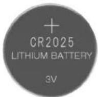
Not Included
*3V CR2025 Battery Required For IR Remote Control
Specifications
| VIDEO: | |
| VIDEO RESOLUTIONS | UP TO 4K 60HZ 4:4:4 |
| VESA RESOLUTIONS | UP TO DCI 4K (4096X2160) 5K (UP TO 5120X3200) |
| HDR FORMATS/RESOLUTIONS | 420, 422, 444 (10 AND 12 DEEP COLOR) HDR10, HDR10+,DOLBY VISION, HLG |
| COLOR SPACE | YUV (COMPONENT), RGB(CSC: REC. 601, REC. 709, BT2020, DCI, P3 D6500) |
| CHROMA SUBSAMPLING | 4:4:4, 4:2:2, 4:2:0 SUPPORTED |
| DEEP COLOR | UP TO 16 BIT (1080), UP TO 12 BIT (4K) |
| AUDIO: | |
| AUDIO FORMATS SUPPORTED HDMI | PCM 2.0 CH, LPCM 5.1 & 7.1, DOLBY DIGITAL, DTS 5.1, DOLBY DIGITAL PLUS, DOLBY TRUEHD, DTS-HD MASTER AUDIO, DTS-X,DOLBY ATMOS |
| AUDIO FORMATS SUPPORTED EXTRACTED (TOSLINK) | PCM 2.0 CH, LPCM 6 CH, LPCM 7 CH, DOLBY DIGITAL, DOLBY DIGITAL PLUS |
| AUDIO FORMATS SUPPORTED EXTRACTED (2CH PORT) | PCM 2 CH |
| AUDIO EXTRACTION LOCATION | FOLLOWS OUTPUT (SELECTABLE) |
| DISTANCE: | |
| HDMI IN/OUT (4K60 4:4:4) | UP TO 50 FEET (USING BULLET TRAIN HDMI) |
| HDMI IN/OUT (W/ AOC CABLE) (4K60 4:4:4) | UP TO 130 FEET (USING BULLET TRAIN AOC) |
| OTHER: | |
| BANDWIDTH | 18 GBPS |
| HDCP | HDCP 2.3 AND EARLIER |
| CONTROL: | |
| PORTS | LAN, RS232, IR WINDOWC4, RTI, ELAN, CRESTRON, URC(FOR MORE INFORMATION - SEE DRIVERS PAGE ONAVPROEDGE.COM/DRIVERS |
| DRIVERS | |
| LAN WEB OS | YES |
| PORTS: | |
| HDMI | TYPE A |
| LAN | RJ45 W/ WEB INTERFACE/ CONTROL |
| AUDIO (EXTRACTED DIGITAL) | TOSLINK |
| AUDIO (EXTRACTED ANALOG) | L/R AUDIO |
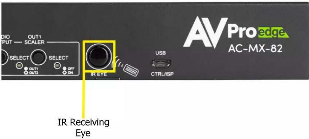
| IR RX | WINDOW ONLY (REMOTE INCLUDED) |
| RS232 | 3 PIN TERMINAL BLOCK |
| ENVIRONMENTAL: | |
| OPERATING TEMPERATURE | 23 TO 125°F (-5 TO 51°C) |
| STORAGE TEMPERATURE | -4 TO 140°F (-20 TO 60°C) |
| HUMIDITY RANGE | 5-90% RH (NO CONDENSATION) |
| POWER: | |
| POWER CONSUMPTION (TOTAL) | 12 WATTS MAX |
| POWER SUPPLY - MATRIX | INPUT: AC 100-240V ~ 50/60HZOUTPUT: DC 12V 2A |
| DIMENSIONS: | |
| DIMENSIONS (UNIT ONLY - HEIGHT/DEPTH/WIDTH) | MM: 33.54 X 111.12 X 28.98INCH: 1.32 X 4.37 X 11.06 |
| DIMENSIONS (PACKAGED HEIGHT/DEPTH/WIDTH) | MM: 93.73 X 222.25 X 393.7INCH: 3.69 X 8.75 X 15.5 |
| WEIGHT (UNIT) | 1.8 LBS (.82 KG) |
| WEIGHT (PACKAGED) | 3 LBS (1.36 KG) |
| DIMENSIONS - RACK MOUNTABLE VERSION(UNIT ONLY - HEIGHT/DEPTH/WIDTH) | MM: 20.5 X 94 X 232.98INCH: .9 X 3.7 X 9.17 |
| DIMENSIONS - RACK MOUNTABLE VERSION(PACKAGED HEIGHT/DEPTH/WIDTH) | MM: 86.61 X 171.45 X 482.6INCH: 3.41 X 6.75 X 19 |
| WEIGHT (UNIT) - RACK MOUNTABLE VERSION | 3.2 LBS (1.45 KG) |
| WEIGHT (PACKAGED) - RACK MOUNTABLE VERSION | 4.4 LBS (2 KG) |
*SPECIFICATIONS SUBJECT TO CHANGE WITHOUT NOTICE. MASS & DIMENSIONS ARE APPROXIMATE
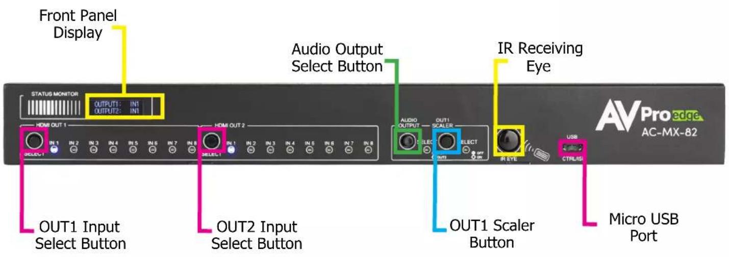
Front and Rear Panel Overview
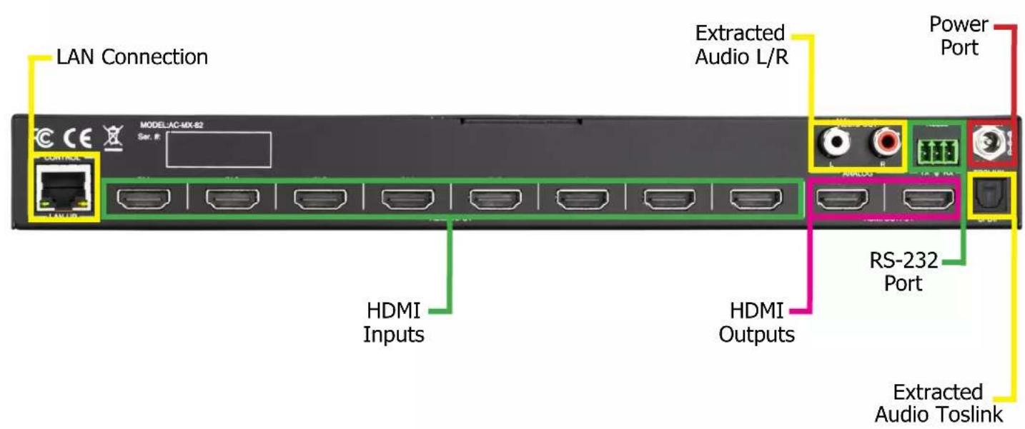
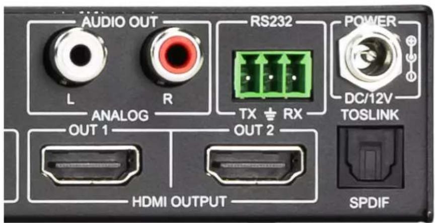
Initial Setup: WebUI
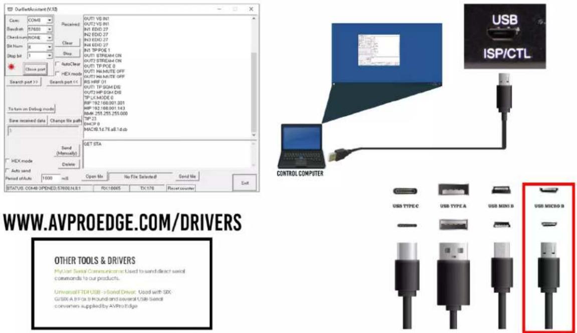
The AC-MX-82 can be controlled using the Micro USB port, 3pin RS232, or over TCP/IP using the LAN connection. For initial setup it is recommended to connect the matrix to a local area network (LAN) and use a computer on the same network in conjunction with the built in WebUI. After making all the physical connections, the first step will be to check for any Firmware Updates. The below steps are an example of this setup, other control options are covered in separate sections of this user manual.
-
Connect the HDMI Input sources to the HDMI Inputs on the back of the matrix.
-
Connect the HDMI/devices to the HDMI Outputs.
-
Connect the network LAN cable to the RJ45 port labeled IP CONTROL.
-
Power on the sources (Inputs).
-
Power on the Output devices/displays.
-
Connect the 12V power supply to power on the matrix and then to a suitable power source.
-
By default DHCP is Enabled and when powered on the AC-MX-82 front panel display will show the devices network settings before displaying INPUT/OUTPUT status. You can also connect to the matrix via the Micro USB port or 3-Pin Terminal then to a computer and send the command GET STA (see page XX for more details). This will reply with the current settings of the matrix including the IP address. If you are able to scan the network, the device will show up with a MAC Vendor labeled as "AVPro Global Hldgs" (see page XX for more details).
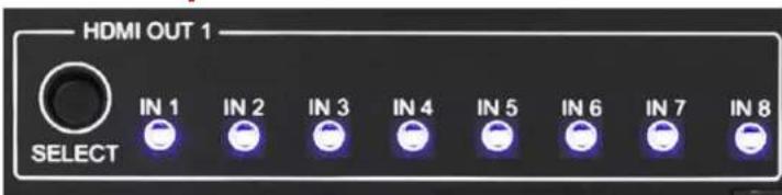
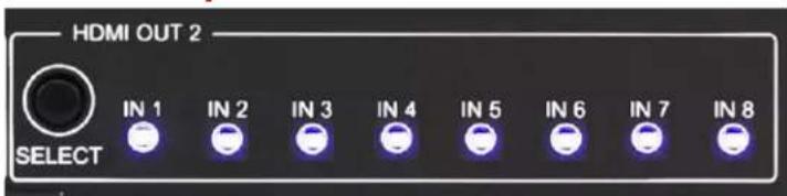
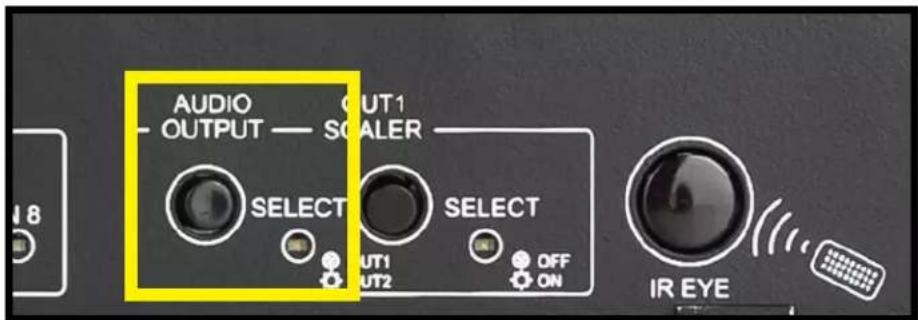
NOTE: To Disable/Enable DHCP using the front panel controls press and hold the AUDIO OUTPUT SELECT button for approximately 3 seconds. If the HDMI OUT1 Input leds flash that means DHCP is Enabled. If the HDMI OUT2 Input leds flsahs that means DHCP is Disabled.
DHCP Enabled
OUT1 Input LEDs will flash once.
DHCP Enabled
OUT2 Input LEDs will flash once.
Default Network Settings
- Router IP 192.168.001.001
• Host IP 192.168.001.239
• Network Mask 255.255.252.000
• TIP 23 -
DHCP 1 (ON)
-
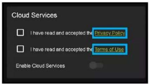
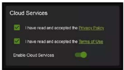
With the WebUI open, navigate to System. Click on the Privacy Policy and Terms of Use, this will open these documents in a new tab for review. Once read click on the boxes next to each to agree. When both are checked the switch for Enable Cloud Services will be selectable (will be red or disabled by default). Click to enable (the switch will turn green).
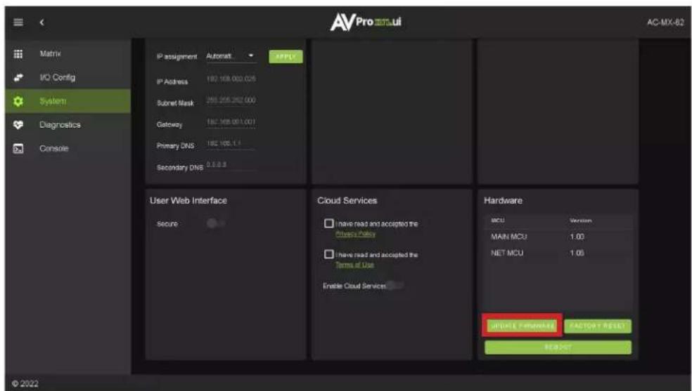
- With the Cloud Services enabled under the Hardware section click the Update Firmware button to check for new Firmware OTA (over the air). This will compare the firmware versions currently loaded on the AC-MX-82 and compare to the latest available. If it is up to date, you will see a prompt stating "No update available!"

- If an update is available, the following prompt will show. Simply click UPDATE.

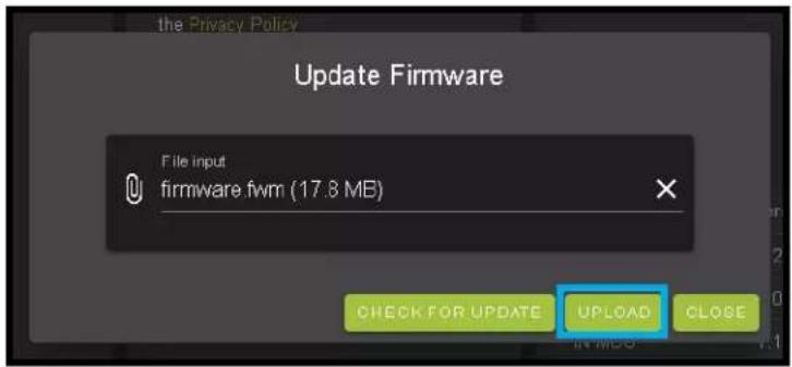
- If a new update is available a file will automatically be selected, simply click the UPLOAD button to load the firmware files to the Matrix. Uploading does not install the Firmware, that is the next step.
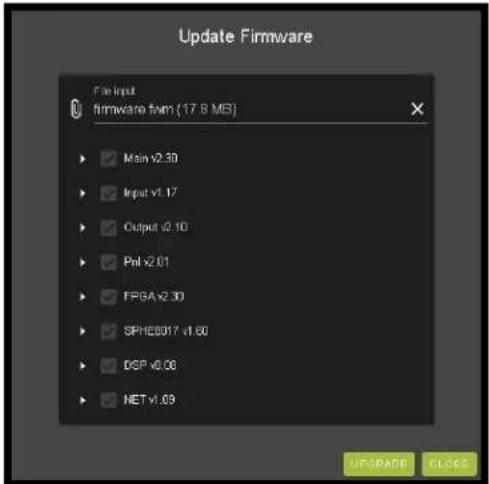
- Once the firmware file has been uploaded, it will display all containing firmware files. Here you can select individual firmware files to load or simply leave all files/options selected. If the version currently installed is not newer (does not need to be updated), then that update will be skipped automatically. Click the UPLOAD button to start.
-
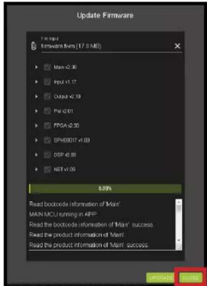
Once the progress bar hits 100% click the CLOSE button, the firmware upgrade process is complete.
-
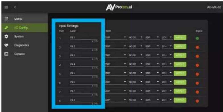
With the Firmware up to date it's time to start setting up the matrix. With the AVPro Edge WebUI open, navigate to the I/O Config section. Label the applicable Inputs (Apple TV, Cable Box, Roku, etc) under the Input Settings - Label.
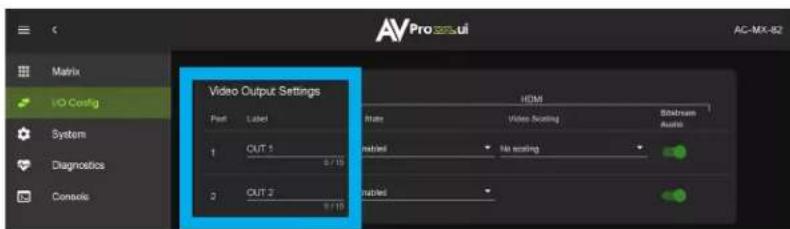
- Label the Outputs (Living Room, Bedroom, Den, etc) under the Video Output Settings - Label
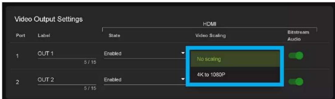
- Set the HDMI Video Scaling if needed. HDMI OUT 1 has two options for scaling, they are:
• No Scaling - Default setting, HDMI OUT1
- 4k to 1080P - This will downscale a 4K signal down to 2k (1080P) on HDMI OUT1
-
With the system and all it's components powered up it's time to verify signal path from source to the sync. For now leave EDID settings to their default 1080P 2CH, the next section Advanced Setup will cover the more advance settings.
-
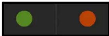
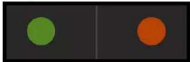
Use the Signal Indicator on the HDMI INPUTS. Green means HDMI source is detected, red means that the source is not detected. If red verify that the input is powered on and that the HDMI cable is properly connected to the source and to the back of the matrix.
natural_image
Two vertical panels showing a green circle on the left and an orange circle on the right, both set against a dark background (no text or symbols)-
Now verify that the connections to the HDMI outputs. If detected the HDMI OUT tab will display some of the connected sync's EDID information like Manufacturer, Preferred Timing, and Deep Color Support. If these fields are blank verify that the sync devices are powered on and that the HDMI/HD cables are properly connected to the back of the matrix.
-
With everything connected and powered on, green indicators across the applicable inputs and outputs, verify you are getting all of your sources on all of your displays.
-
Problems with a source or sync, see the Troubleshooting section for help on page 35.
Advanced Setup: WebUI Input Settings
After verifying good signal path from source to sync now it is time to go through the rest of the settings to maximize the setup. Starting with the input side with the EDID and Audio Mode settings.
- With the WebUI open, navigate to the I/O Config tab and focus on the Input Settings section at the top.
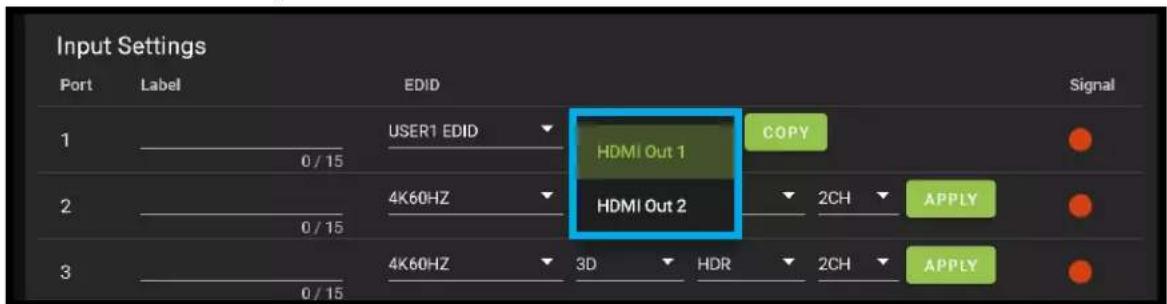
- Set the EDID on each input by selecting the resolution drop-down first (default is set to 1080P). The options are 1080P, 4K30Hz, 4K60Hz Y420, and 4K60Hz. If you select USER1 EDID, then the drop-downs change to allow you to select from and output to copy from. You can select any of the 4 HDMI outputs then click the COPY button. This will save that outputs EDID to the USER1 slot.
- Next use the drop-down to select NO 3D, or 3D depending on the displays capability.
NOTE: Currently the only resolution you can choose NO 3D for is 1080P.
-
Next drop-down select either SDR (standard dynamic range) or HDR (High Dynamic Range).
-
The fourth drop-down in the EDID section is for the audio, you can select 2CH, 6CH, or 8CH.
-
Click the APPLY button to set the EDID.
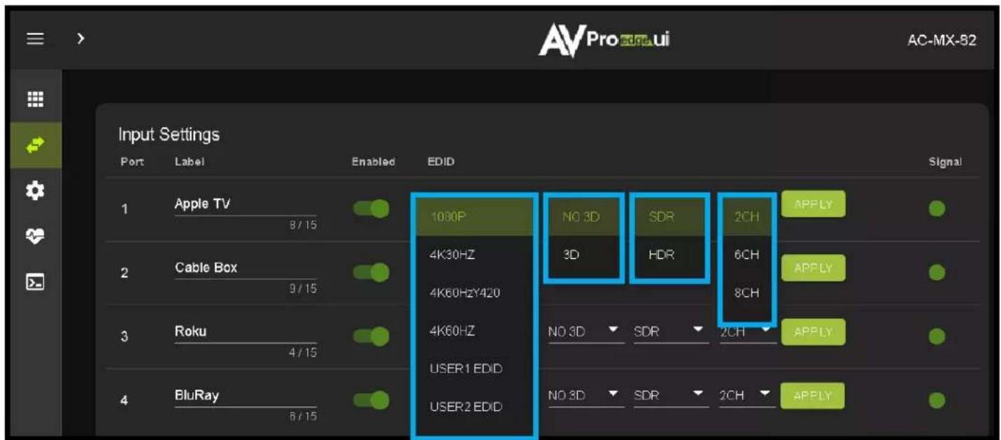
- Verify you are still getting that source to all your displays and that the image looks correct.
NOTE: Some older displays may take an HDR signal and display correctly (ignoring the HDR Metadata) others will not ignore the HDR part of the signal and may display incorrectly.
Advanced Setup: WebUI Output Settings
-
Now navigate to the Video Output Settings under I/O Config
-
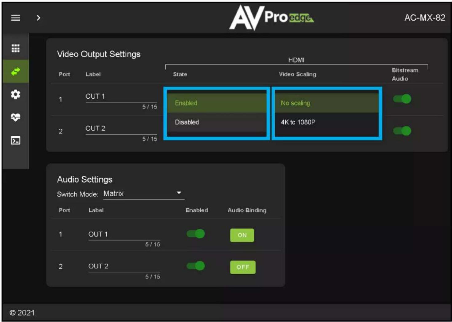
In addition to the output Label (name/alias), there are 3 settings for each HDMI output.
-
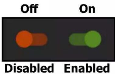
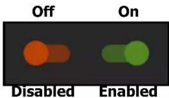
Under State, you can enable/disable that port (turn that port on or off), turn on downscaling on HDMI OUT1 (HDMI you can choose to No Scaling or 4K to 1080P), and you can Enable or Disable the Bitstream Audio (slider icon Green=ON, Red=OFF).
Advanced Setup: WebUI Extracted Audio Output Settings
-
Now navigate to the Extracted Audio Output Settings under I/O Config.
-
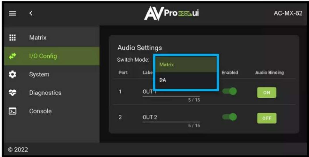
The extracted audio ports have 2 distinct operating modes, use the drop-down at the top to select. The two options are.
Matrix (Default)- This mode allows you to matrix the extracted audio ports independently from the HDMI outputs. In this mode you in order to select, you will use the Audio Binding buttons on the right to choose the OUTPUT (OUT1 or OUT2) which the audio will follow.
DA - where the audio port number corresponds to the input signal. This is ideal for systems where audio is matrixed separately in a zoned amplifier.
- Other available settings for the extracted audio ports include Enable/Disable and Audio Binding selection (OUT1 or OUT2 selectable when in Matrix Mode).
NOTE: The Left Right Analog Audio Output only supports 2Ch audio. The Toslink port supports up to 5.1Ch audio. This means if the source is outputing 5.1 then the Left Right Analog Audio Output will be muted. If using the Left Right Analog Audio output, make sure the sources are set to output 2Ch audio.
WebUI: Video Matrix
Use this page to route the video INPUTS and OUTPUTS.
- Click on the INPUT number to select (example below shows IN 1)
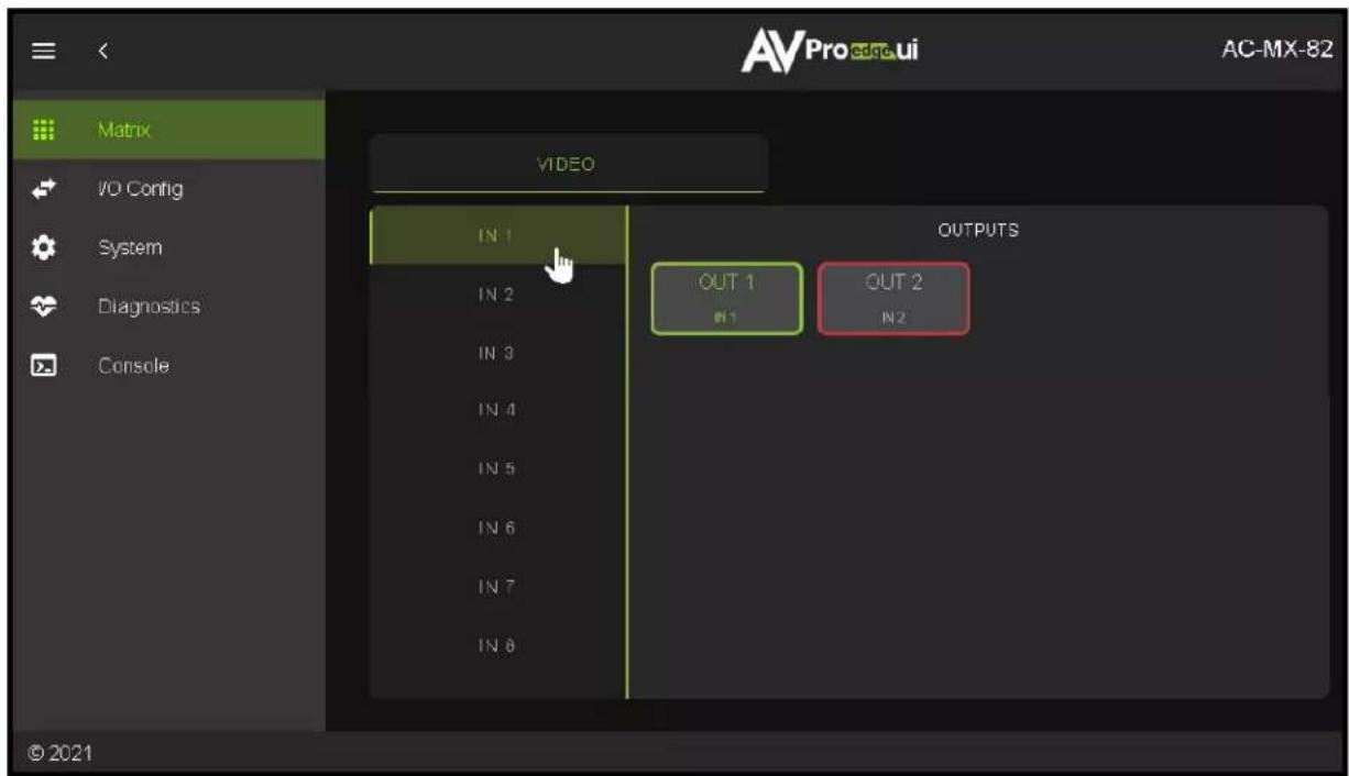
- With the INPUT selected simply click on the OUTPUT you want to send that source to.
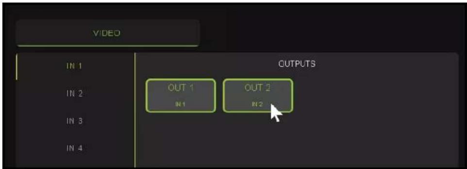
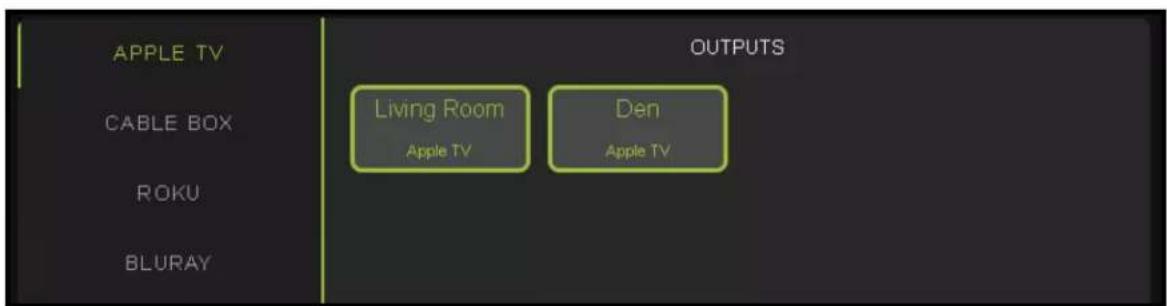
- Note: If you rename the INPUTS/OUTPUTS using the I/O Config page they will display here.
WebUI: I/O Config - Input Settings
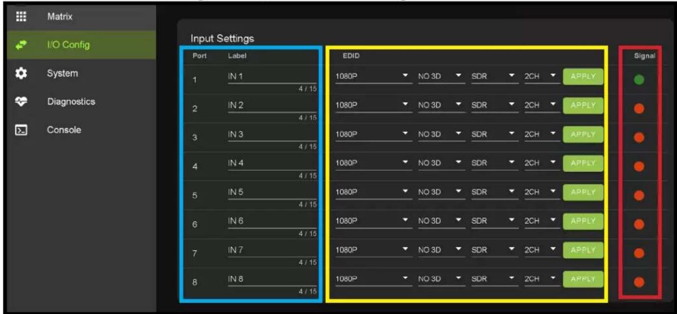
Input Settings Label - Use this to give an name/alias to your inputs (Apple TV, Cable Box, Roku, etc). Note: There is a 15 character limit to this field, the name will replace the default "IN #" throughout the rest of the WebUI (for instance the Video Matrix tab).
Input Settings EDID - Use these four drop-downs to select your preferred EDID. The available combinations are as follows.
- 1080P_2CH
- 1080P_6CH
- 1080P_8CH
- 1080P_3D_2CH
- 1080P_3D_6CH
- 1080P_3D_8CH
- 4K30HZ_3D_2CH
- 4K30HZ_3D_6CH
- 4K30HZ_3D_8CH
- 4K60HzY420_3D_2CH
- 4K60HzY420_3D_6CH
- 4K60HzY420_3D_8CH
- 4K60HZ_3D_2CH
- 4K60HZ_3D_6CH
- 4K60HZ_3D_8CH
- 1080P_2CH_HDR
- 1080P_6CH_HDR
- 1080P_8CH_HDR
- 1080P_3D_2CH_HDR
- 1080P_3D_6CH_HDR
- 1080P_3D_8CH_HDR
- 4K30HZ_3D_2CH_HDR
- 4K30HZ_3D_6CH_HDR
-
4K30HZ_3D_8CH_HDR
-
4K60HzY420_3D_2CH_HDR
-
4K60HzY420_3D_6CH_HDR
-
4K60HzY420_3D_8CH_HDR
-
4K60HZ_3D_2CH_HDR
-
4K60HZ_3D_6CH_HDR
-
4K60HZ_3D_8CH_HDR
NOTE: If you select USER1 EDID, then drop-downs change to allow you to select from and output to copy from. You can select any of the 2 HDMI outputs then click the COPY button (this replaces the Apply button). This will save that outputs EDID to the USER1 slot.
WebUI: I/O Config - Input Settings Cont.
Input Settings Signal - The Signal Indicator on the HDMI INPUTS shows the current state of the connection HDMI source. Green means the HDMI source is detected, red means that the source is not detected. If red verify that source is powered on and that the HDMI cable is properly connected to the source and to the back of the matrix.
natural_image
Two solid-colored circles, one green and one orange, on a dark background (no text or symbols)WebUI: I/O Config - Output Settings
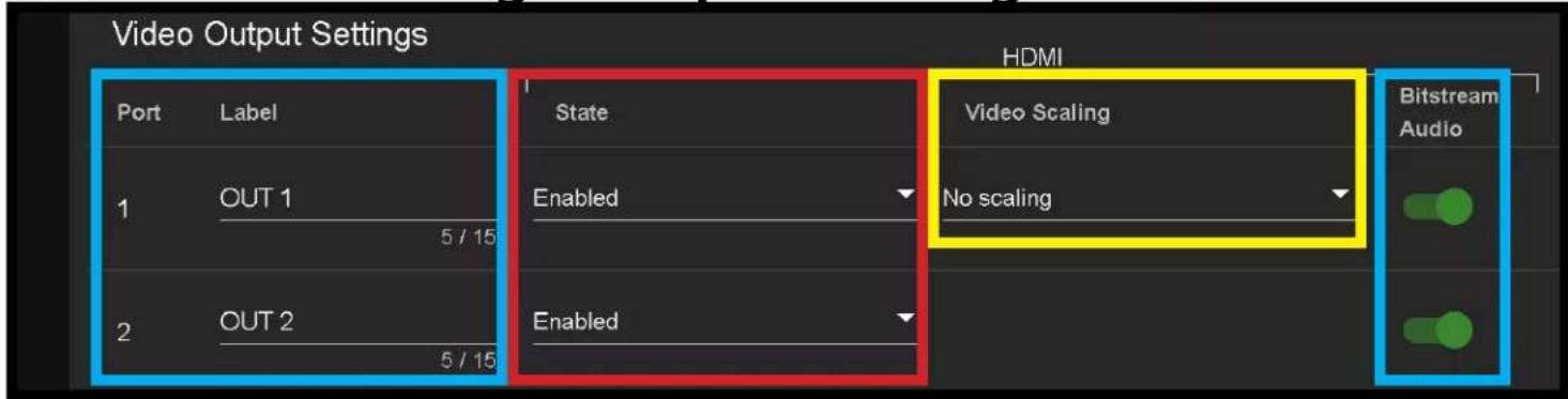
Output Settings Label - Use this to give an name/alias to your outputs (Living Room, Den, Kitchen, etc).
Note: There is a 15 character limit to this field, the name will replace the default "OUT #" throughout the rest of the WebUI (for instance the Video Matrix tab).
Output Settings State - This drop-down has 3 settings, just like the input settings you can Enable or disable this port. In addition you can also choose Test Pattern to enable a 1080P color bar test pattern on that output. This is helpful in verifying the signal chain from Matrix to sync (display). To disable the test pattern, change the state back to Enabled (default).
Output Settings Video Scaling - The HDMI outputs can down-scale a 4K signal to 1080P on OUTPUT1. This scaling only changes the pixel density, it does not alter frame rate or colorspace.
Output Settings Bitstream Audio - This is an enable/disable switch. By default this will be Enabled/Green. To change the setting simply click to switch. Disabled/Red there will be no Audio passed on that HDMI output.
NOTE: This setting has no affect on the Extracted Audio outputs.
WebUI: I/O Config - Audio Settings
This area contains relevant audio settings and information of the AC-MX-82.
Host Name - Devices name on the network. This field is automatically filled with Model Name by default.
Model Name - Displays the AVProEdge Model/Part number.
MAC Address - Displays the devices MAC Address.
IP assignment - This drop-down has two options.
- Manual
- Automatic (DHCP)
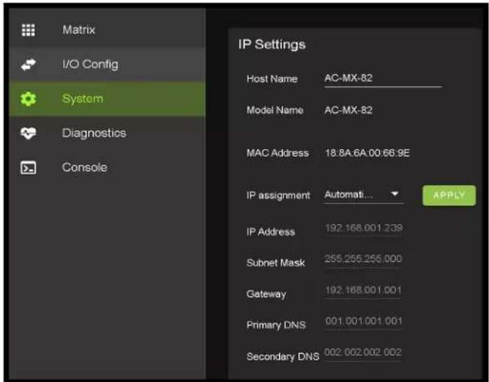
Default out of the box will be set to Automatic (DHCP), the IP Address, Subnet Mask, Gateway, Primary DNS, and Secondary DNS will be assigned by your network controller. If you select Manual, you can use the text fields to enter your own Network settings. Once all fields have been filled out, click the green Apply Button to set. A prompt will appear to confirm the change, click OK to confirm.
WebUI: System - IP Control
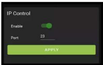
This area contains relevant IP Control settings for the AC-MX-82. There are two fields that can changed, Enable Disable switch and the Port Number.
- Enable - This switch has two options, Green/Enabled (Default) and Red/Disabled.
- Port - This field is used to change the Telnet Port of the AC-MX-82. You can use the text filed to enter a number or use the Up/Down arrow buttons to increase/decrease the number.
WebUI: System - Admin Web Interface
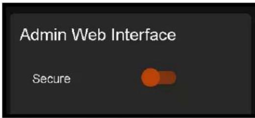
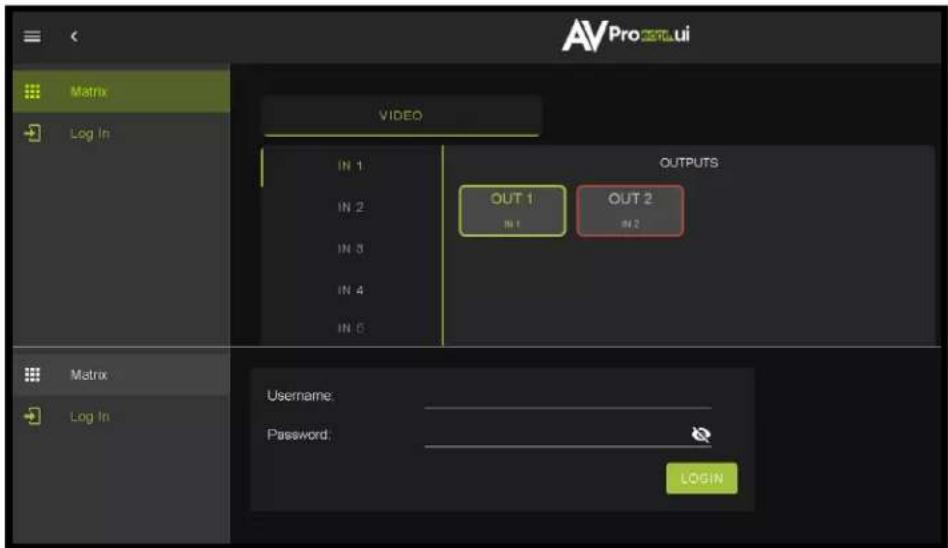
This switch has two options, Red/Disabled (Default) and Green/Enabled. When enabled (green) there will be three fields that appear, Username, Password, and Confirm Password.
Default Username - admin
Default Password - admin
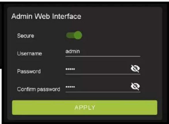
Once the desired Username and Password has been entered, click the green APPLY button to set.
With the Admin Web Interface enabled, the only menu that will be accessible using the WebUI will be the Matrix tab. The rest of the settings will require the Admin log in to access.
WebUI: System - User Web Interface
This switch has two options, Red/Disabled (Default) and Green/Enabled. When enabled (green) there will be three fields that appear, Username, Password, and Confirm Password.
NOTE: The Admin Web Interface must first be Enabled and setup before this field will be available to change.
Default Username - user
Default Password - user123
Once the desired Username and Password has been entered, click the green APPLY button to set.
Note: The webpage will reload to the Log In page.

With both Admin and User Web Interfaces enabled, no menus will be accessible using the WebUI without first logging in (see image below).
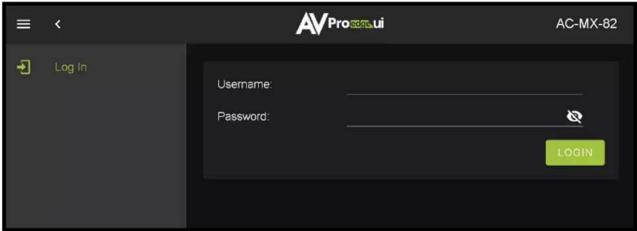
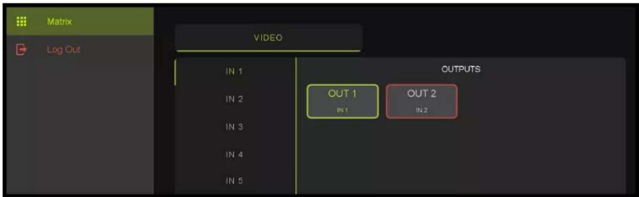
Logging in with the User credentials, the only menu that will be accessible will be the Matrix tab. The rest of the settings will require the Admin user to log in (see page 24).
WebUI: System - Cloud Services
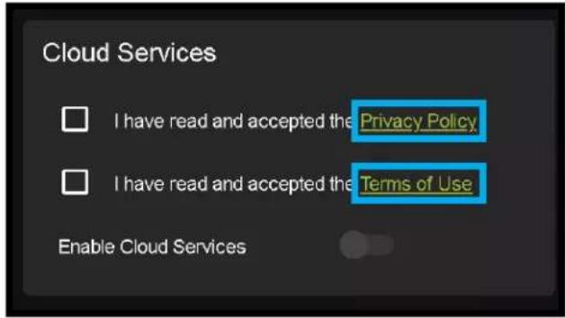
By enabling Cloud Services your device will have the ability to connect to firmware servers for over-the-air (OTA) updates and enable third-party remote management services. If Cloud Services are disabled, your device will opt-out of any previously enabled services and will not be able to access OTA updates.
Before you can enable the cloud services you must first agree to the "Privacy Policy" and "Terms of Use".
You can view these documents by clicking on Privacy Policy or Terms of Use links, this will open up a PDF copy of that document in a new tab.
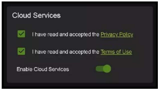
With the Cloud Services enabled you can use the System tab to check for new Firmware OTA (over the air).
This will check the firmware versions currently loaded on the AC-MX-82 and compare to the latest available. If it is up to date, you will see a prompt stating "No update available!" click CLOSE to exit.

If an update is available, the following prompt will show. Simply click the UPDATE button to load.

NOTE: When loading firmware (depending on the firmware files that are being updated) some settings will revert back to Factory Defaults. Take note of the I/O Config tab. Settings like the INPUT/OUTPUT labels, EDID Settings, Video Scaling, Audio Settings, etc. as they will have to be re-applied after the firmware updates are completed.
If an update is available a file will automatically be selected, simply click the UPLOAD button to load the firmware files to the Matrix.
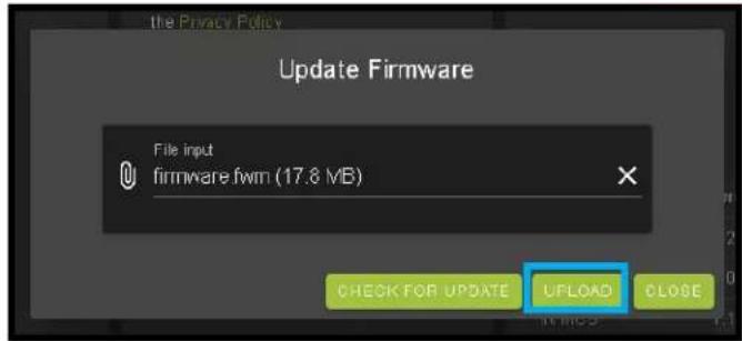
WebUI: System - Firmware Update Cont.
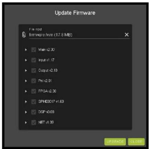
Once the firmware file has been uploaded, it will display all containing firmware files. Here you can select individual firmware files to load or simply leave all files/options selected. If the version currently installed not newer, then that update will be skipped automatically.
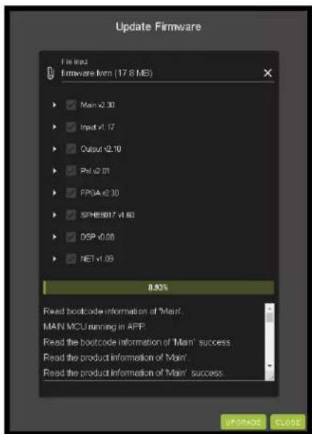
Once the progress bar hits 100% click the CLOSE button, the firmware upgrade process is complete.
Now you will want to go back and re-apply settings like INPUT/OUTPUT Labels, applied EDIDs, Video Scaler Settings, Audio Settings, etc.
WebUI: System - Hardware
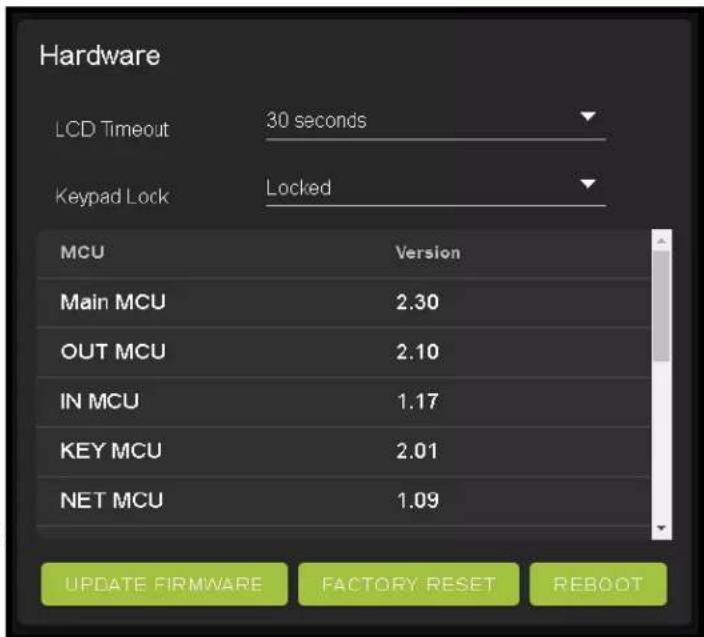
LCD Timeout - This adjusts the time the front panel display will stay lit up when a button is pressed.
There are four setting available
- Always on (Default)
- 15 Seconds
- 30 Seconds
- 45 Seconds
Keypad Lock - Enable or Disable (default) the front panel Keypad Lock.
MCU/Version - Lists the current Firmware Versions
UPDATE FIRMWARE - Check/upload firmware.
FACTORY RESET - Restores matrix to Factory Defaults
REBOOT - Reboots the AC-MX-82
WebUI: Diagnostics - HDMI IN
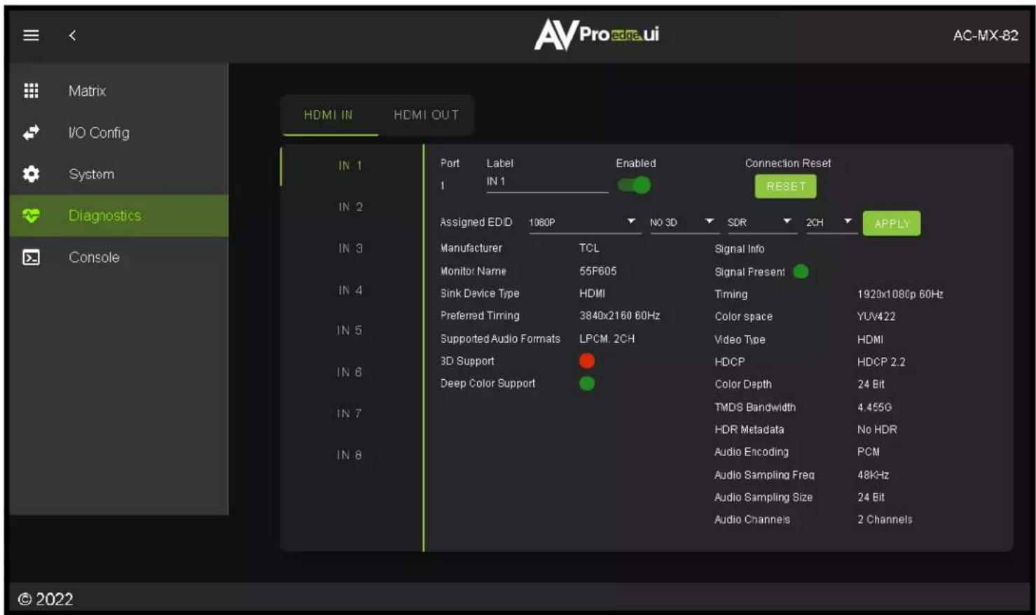
Input Settings Label - Use this to give an name/alias to your inputs (Apple TV, Cable Box, Roku, etc). Note :There is a 15 character limit to this field, the name will replace the default "IN #" throughout the rest of the WebUI (for instance the Video Matrix tab).
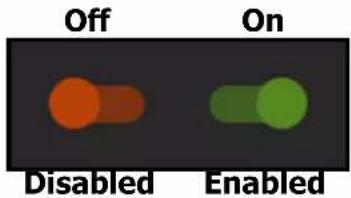
Input Settings Enable switch - Use this enable/disable switch to turn the corresponding Input port on or off. The default setting is enabled (green) by default.
Connection Reset - Use this button to perform a reset of the HDMI Input connection.
Input Settings EDID - Use these four drop-downs to select your preferred EDID. The available combinations are as follows.
-
1080P_2CH
-
1080P_6CH
-
1080P_8CH
-
1080P_3D_2CH
-
1080P_3D_6CH
-
1080P_3D_8CH
-
4K30HZ_3D_2CH
-
4K30HZ_3D_6CH
-
4K30HZ_3D_8CH
-
4K60HzY420_3D_2CH
-
4K60HzY420_3D_6CH
-
4K60HzY420_3D_8CH
-
4K60HZ_3D_2CH
-
4K60HZ_3D_6CH
-
4K60HZ_3D_8CH
-
1080P_2CH_HDR
-
1080P_6CH_HDR
-
1080P_8CH_HDR
-
1080P_3D_2CH_HDR
-
1080P_3D_6CH_HDR
-
1080P_3D_8CH_HDR
-
4K30HZ_3D_2CH_HDR
-
4K30HZ_3D_6CH_HDR
-
4K30HZ_3D_8CH_HDR
-
4K60HzY420_3D_2CH_HDR
-
4K60HzY420_3D_6CH_HDR
-
4K60HzY420_3D_8CH_HDR
-
4K60HZ_3D_2CH_HDR
-
4K60HZ_3D_6CH_HDR
-
4K60HZ_3D_8CH_HDR
WebUI: Diagnostics - HDMI IN Cont.
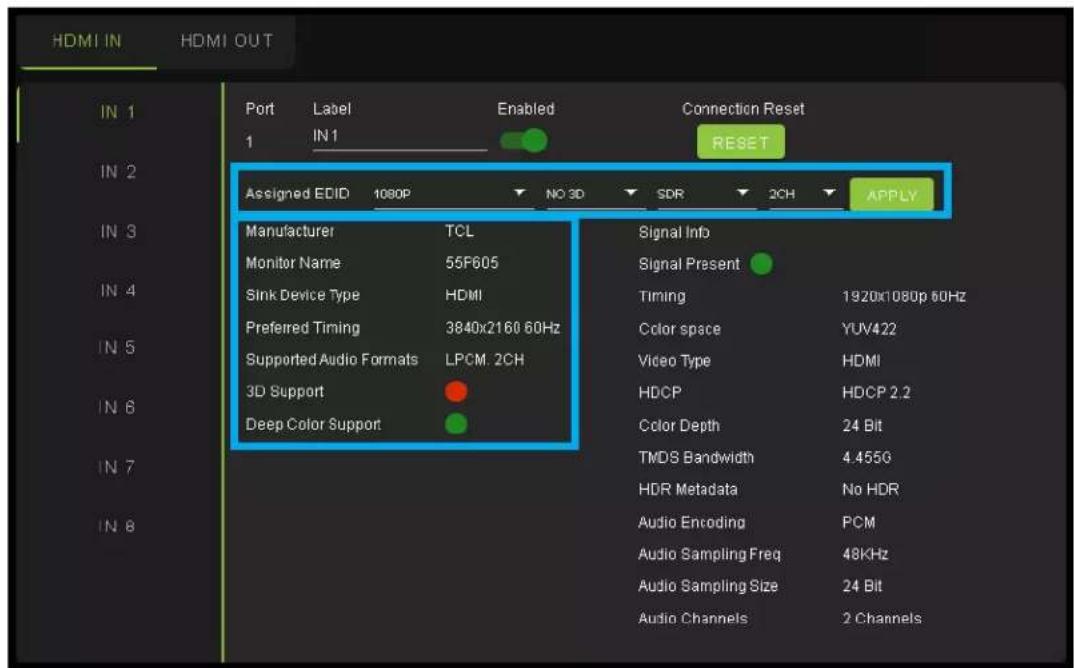
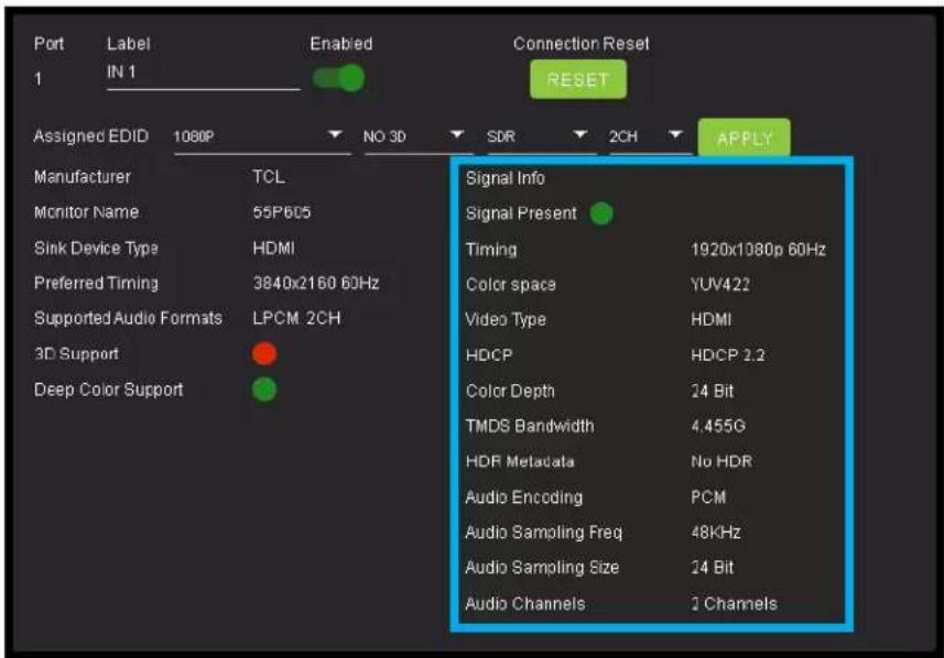
On the left, you will see the current applied EDID information. In the example above, you will see a canned 1080P - No 3D - SDR - 2CH EDID applied to IN 1. Any EDID change, once applied will display here.
Signal Info shows the connected source's current output information. This includes
- Timing
- Color Space
- Video Type
- HDCP Version
- TMDS Bandwidth
- HDR Metadata
• Audio Sampling Frequency - Audio Sampling Size
- Audio Channels
WebUI: Diagnostics - HDMI OUT
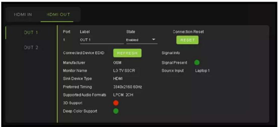
HDMI Output Label, State, and Connection Reset.
Connected Device EDID shows the connected sync's preferred EDID information and current state.
This includes
- Manufacturer
- Monitor Name
- Sink Device Type
- Preferred Timing
• Supported Audio Formats
• 3d Support - Deep Color Support
- Signal Present
• Source Input (future update)
WebUI: Console
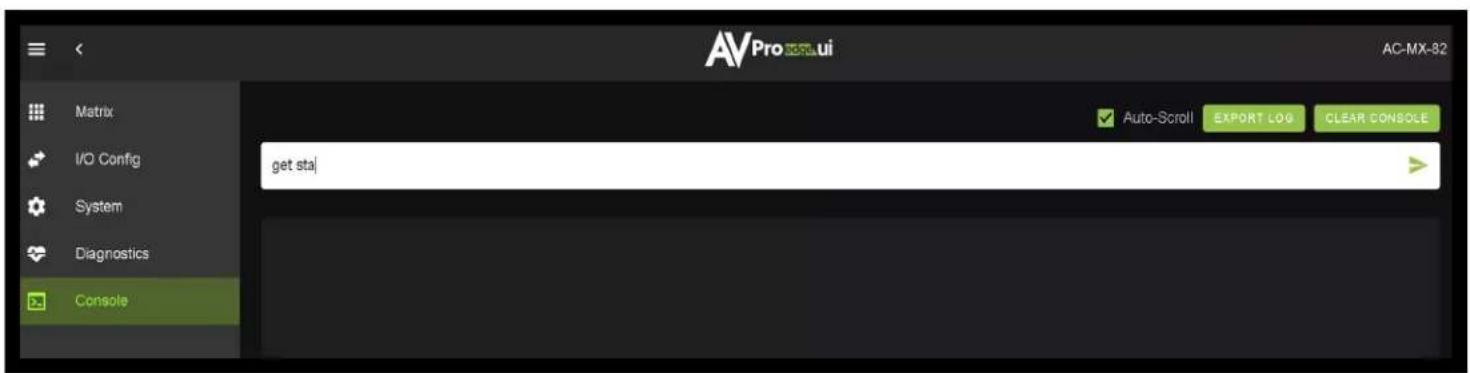
There is a built in Command Console
Using the command API (command list) you can send device specific commands or use as a live monitor while sending commands from a control system (helpful in troubleshooting).
Example
- Click in the white box and type
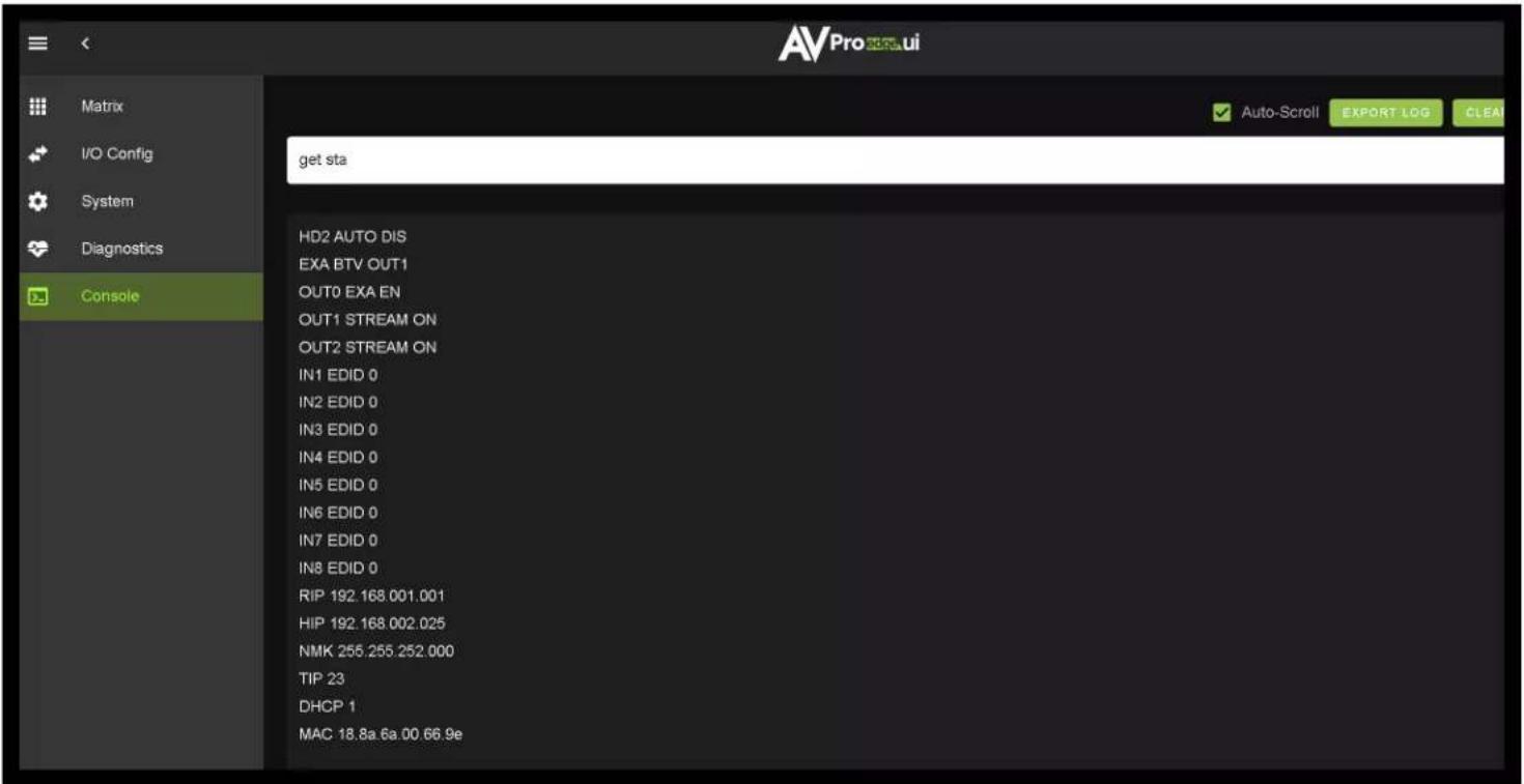
a. GET STA
Click the green arrow or hit ENTER/RETURN on your keyboard
The the command response will show in the field below.
Front Panel Control - Functional Mode Button
The AC-MX-82 has two switching modes Single Switch and Double Switch (see command list on Page XX for more details. This modes can be switched via the front panel controls by pressing and holding OUT2 and AUDIO OUTPUT buttons together for approximately 5 seconds. The OUT2 LEDs will flash confirming the change.
- Single Switch - The two outputs can be switched independently by pressing either the OUT1 SELECT button or the OUT2 SELECT button.
- Double Switch - The two outputs will switch together. This means if you switch OUT1 to INPUT2 with the front panel OUT1 SELECT button, OUT2 will also switch to INPUT2. This is the same if you change inputs using any of the available control options (front panel, LAN, RS-232, IR, etc).
Front Panel Control - Matrix Mode Switching
The AC-MX-82 can switch the two OUTPUTS independently from the front panel by pressing the OUT1 SELECT or OUT2 SELECT buttons
- Press the OUT1 SELECT button to cycle through the 4 available inputs.
- Press the OUT2 SELECT button to cycle through the 4 available inputs.

Front Panel Control - DA Mode Switching
The AC-MX-82 can switch the two OUTPUTS at the same time from the front panel by pressing either the OUT1 SELECT or OUT2 SELECT button.
- Press the OUT1 SELECT button to cycle through the 4 available inputs on both outputs.
- Press the OUT2 SELECT button to cycle through the 4 available inputs on both outputs.

Front Panel Control - Audio Output
The Audio Output Select button has two states, they are as follows. Single press the button to change between the two.
- AUDIO OUTPUT LED will be off - this means the extracted audio ports will follow HDMI OUT1.

- AUDIO OUTPUT LED will be on - This means the extracted audio ports will follow HDMI OUT2.

Front Panel Control - EDID Management:
This matrix has 30 factory defined EDID settings. It also has 3 user defined EDID memories. The user EDID memories are independent to each input and can be set separately. The user defined EDID can be uploaded using the free PC Control software or RS-232. In addition, you can choose to read the EDID from the desired output and the captured EDID will automatically store and overwrite the EDID in “USER EDID 1” and will be applied to the selected source.
To Change the EDID setting:
- Press and hold both "Out 1" and "Out 2" buttons for 5 seconds.
All LED flash one time. You are now in EDID management state.
-
In the EDID management state, press the "Out 1" button to toggle to the input you want to set the EDID for. (1=IN1, 2=IN2, 3=IN3, 4=IN4)
-
Press the "Out 2" button to toggle through the EDID index.
-
Once you land on the EDID you want to use, press and hold the "Out 2" button for 3 seconds. All LEDs will flash one time indicating success
NOTE: When in the EDID management state, if you are inactive for 10 seconds it will return to the normal state automatically. All LEDs flash one time.
These are the pre-defined EDID settings that you can toggle through:
| 1. | 1080P_2CH | 12. | 4K60HzY420_3D_8CH | 23. | 4K30HZ_3D_8CH_HDR |
| 2. | 1080P_6CH | 13. | 4K60HZ_3D_2CH | 24. | 4K60HzY420_3D_2CH_HDR |
| 3. | 1080P_8CH | 14. | 4K60HZ_3D_6CH | 25. | 4K60HzY420_3D_6CH_HDR |
| 4. | 1080P_3D_2CH | 15. | 4K60HZ_3D_8CH | 26. | 4K60HzY420_3D_8CH_HDR |
| 5. | 1080P_3D_6CH | 16. | 1080P_2CH_HDR | 27. | 4K60HZ_3D_2CH_HDR |
| 6. | 1080P_3D_8CH | 17. | 1080P_6CH_HDR | 28. | 4K60HZ_3D_6CH_HDR |
| 7. | 4K30HZ_3D_2CH | 18. | 1080P_3D_2CH_HDR | 29. | 4K60HZ_3D_8CH_HDR |
| 8. | 4K30HZ_3D_6CH | 19. | 1080P_3D_6CH_HDR | 30. | User EDID 1 |
| 9. | 4K30HZ_3D_8CH | 20. | 1080P_3D_8CH_HDR | 31. | User EDID 2 |
| 10. | 4K60HzY420_3D_2CH | 21. | 4K30HZ_3D_2CH_HDR | 32. | User EDID 3 |
| 11. | 4K60HzY420_3D_6CH | 22. | 4K30HZ_3D_6CH_HDR |
*You may also copy EDID from any output and apply to any input, simply select "Copy EDID from Output x" (x=1-4). This will copy the EDID from the display attached and store it into "User EDID 1" and apply it to the input you have selected.
NOTE: See next page for diagram showing the EDID list and their corresponding LED lights.

EDID Management:
| The LED Status: | 0(OFF) | 1(ON) | |||||
| LED | (OUT2)IN1 | (OUT2)IN2 | (OUT2)IN3 | (OUT2)IN4 | (OUT2)IN5 | (OUT2)IN6 | EDID |
| 0 | 0 | 0 | 0 | 0 | 0 | 0 | 0: 1080P_2CH(PCM) |
| 1 | 1 | 0 | 0 | 0 | 0 | 0 | 1: 1080P_6CH |
| 2 | 0 | 1 | 0 | 0 | 0 | 0 | 2: 1080P_8CH |
| 3 | 1 | 1 | 0 | 0 | 0 | 0 | 3: 1080P_3D_2CH(PCM) |
| 4 | 0 | 0 | 1 | 0 | 0 | 0 | 4: 1080P_3D_6CH |
| 5 | 1 | 0 | 1 | 0 | 0 | 0 | 5: 1080P_3D_8CH |
| 6 | 0 | 1 | 1 | 0 | 0 | 0 | 6: 4K30HZ_3D_2CH(PCM) |
| 7 | 1 | 1 | 1 | 0 | 0 | 0 | 7: 4K30HZ_3D_6CH |
| 8 | 0 | 0 | 0 | 1 | 0 | 0 | 8: 4K30HZ_3D_8CH |
| 9 | 1 | 0 | 0 | 1 | 0 | 0 | 9: 4K60HZ(Y420)_3D_2CH(PCM) |
| 10 | 0 | 1 | 0 | 1 | 0 | 0 | 10: 4K60HZ(Y420)_3D_6CH |
| 11 | 1 | 1 | 0 | 1 | 0 | 0 | 11: 4K60HZ(Y420)_3D_8CH |
| 12 | 0 | 0 | 1 | 1 | 0 | 0 | 12: 4K60HZ_3D_2CH |
| 13 | 1 | 0 | 1 | 1 | 0 | 0 | 13: 4K60HZ_3D_6CH |
| 14 | 0 | 1 | 1 | 1 | 0 | 0 | 14: 4K60HZ_3D_8CH |
| 15 | 1 | 1 | 1 | 1 | 0 | 0 | 15: 1080P_2CH(PCM)_HDR |
| 16 | 0 | 0 | 0 | 0 | 1 | 0 | 16: 1080P_6CH_HDR |
| 17 | 1 | 0 | 0 | 0 | 1 | 0 | 17: 1080P_8CH_HDR |
| 18 | 0 | 1 | 0 | 0 | 1 | 0 | 18: 1080P_3D_2CH(PCM)_HDR |
| 19 | 1 | 1 | 0 | 0 | 1 | 0 | 19: 1080P_3D_6CH_HDR |
| 20 | 0 | 0 | 1 | 0 | 1 | 0 | 20: 1080P_3D_8CH_HDR |
| 21 | 1 | 0 | 1 | 0 | 1 | 0 | 21: 4K30HZ_3D_2CH(PCM)_HDR |
| 22 | 0 | 1 | 1 | 0 | 1 | 0 | 22: 4K30HZ_3D_6CH_HDR |
| 23 | 1 | 1 | 1 | 0 | 1 | 0 | 23: 4K30HZ_3D_8CH_HDR |
| 24 | 0 | 0 | 0 | 1 | 1 | 0 | 24: 4K60HZ(Y420)_3D_2CH(PCM)_HDR |
| 25 | 1 | 0 | 0 | 1 | 1 | 0 | 25: 4K60HZ(Y420)_3D_6CH_HDR |
| 26 | 0 | 1 | 0 | 1 | 1 | 0 | 26: 4K60HZ(Y420)_3D_8CH_HDR |
| 27 | 1 | 1 | 0 | 1 | 1 | 0 | 27: 4K60HZ_3D_2CH(PCM)_HDR |
| 28 | 0 | 0 | 1 | 1 | 1 | 0 | 28: 4K60HZ_3D_6CH_HDR |
| 29 | 1 | 0 | 1 | 1 | 1 | 0 | 29: 4K60HZ_3D_8CH_HDR |
| 30 | 0 | 1 | 1 | 1 | 1 | 0 | 30: USER1_EDID |
| 31 | 1 | 1 | 1 | 1 | 1 | 0 | 31: USER2_EDID |
| 32 | 0 | 0 | 0 | 0 | 0 | 1 | 32: USER3_EDID |
IR Control: IR Remote
IR Remote Control:
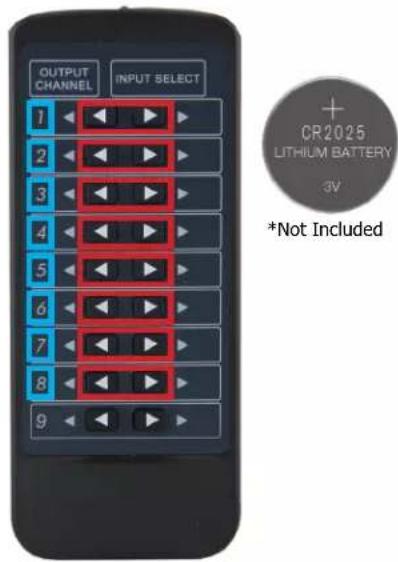
When routing HDMI, the matrix can be controlled by using the IR remote supplied with the product (battery not included, requires CR2025).
The labels on the right are the OUTPUT numbers.
The left arrow button decrements to the next input port, and the right arrow increments to the next input port.
The arrows are for changing a desired INPUT.
RS-232 and TCP/IP Control:
The AC-MX-82 can be controlled with either RS-232 or TCP/IP commands. Certain switching or format configurations can only be done using these commands. We recommend using either the MyUART (RS-232 - free) or Hercules (TCP/IP - free) apps as they are very easy to use for sending commands to the machine.
For TCP/IP control commands use Telnet Port 23.
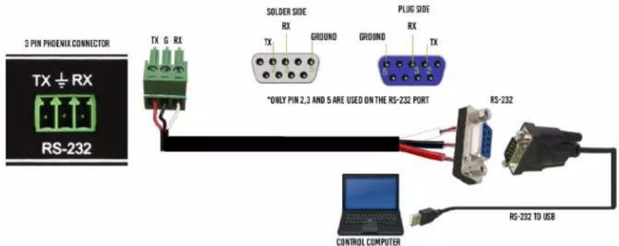
For RS-232, use a null modem serial cable adapter and set the serial communications to: 57600,n,8,1 (baud: 57600, no parity, 8 data bits and 1 stop bit) with no handshaking.
Please add a return (Enter key) after each command when using direct commands.
The unified command list (ASCII) is listed on the following pages. Text version available here, and under the resources tab of on the products web page.
USB CONTROL FOR AVPRO EDGE
RS-232 CABLE FOR AVPRO EDGE
Command List:
• Baudrate: 57600
- Checksum: None
- Bit Num: 8
- Stop Bit: 1
| Command | Action | |
| H | : Help | |
| STA | : Show Global System Status | |
| SET RST | : Reset to Factory Defaults | |
| SET RBT | : Set System to Reboot | |
| SET ADDR xx | : Set System Address to xx {xx=[00-99](00=Single)} | |
| GET ADDR | : Get System Address | |
| GET STA | : Get System System Status | |
| GET INx SIG STA | : Get Input x Signal Status{x=[0~8](0=ALL)} | |
| Output Setup Commands: | ||
| SET OUTx VS INy | : Set Output x To Input y{x=[0-2](0=ALL), y=[1-8]} | |
| SET OUT1 VIDEOy | : Set Output1 VIDEO Mode {y=[1,2](1=Bypass Mode,2=4K->2K)} | |
| SET EXA BTV OUTx | : Set Ex-Audio Output bind to Outputx{x=[1~2]} | |
| SET SWITCH MODEx | : Set Switch Mode To Single Switch or Double Switch{x=[0~1]} | |
| SET OUTx EXA EN/DIS | : Set Ex-Audio Output Enable/Disable{x=[0](0=ALL)} | |
| SET OUTx STREAM ON/OFF | : Set Output x Stream ON/OFF{x=[0~2](0=ALL)} | |
| SET OUTx HA MUTE ON/OFF | : Set HDMI Output x Audio Mute ON/OFF{x=[0~2](0=ALL)} | |
| GET OUTx VS | : Get Output x Video Route{x=[0~2](0=ALL)} | |
| GET OUT1 VIDEO | : Get Output1 Video Mode | |
| GET EXA BTV OUT | : Get Ex-Audio Output bind to which Output | |
| GET SWITCH MODE | : Get Switch Mode | |
| GET OUTx EXA | : Get Ex-Audio Output Enable/Disable Status{x=[0](0=ALL)} | |
| GET OUTx EDID DATA | : Get Output x EDID DATA{x=[1~2]} | |
| GET OUTx STREAM | : Get Output x Stream ON/OFF Status{x=[0~2](0=ALL)} | |
| GET OUTx HA MUTE | : Get HDMI Output x Audio Mute Status{x=[0~2](0=ALL)} | |
| Input Setup Commands: (Note: Input number(x)=HDMI(x),x=1-8) | ||
| SET INx EDID y | : Set Input x EDID{x=[0~8](0=ALL), y=[0~32]} | |
| 0:1080P_2CH(PCM) | 1:1080P_6CH | 2:1080P_8CH |
| 3:1080P_3D_2CH(PCM) | 4:1080P_3D_6CH | 5:1080P_3D_8CH |
| 6:4k30Hz_3D_2CH(PCM) | 7:4k30Hz_3D_6CH | 8:4k30Hz_3D_8CH |
| 9:4K60Hz(Y420)_3D_2CH(PCM) | 10:4K60Hz(Y420)_3D_6CH | 11:4K60Hz(Y420)_3D_8CH |
| 12:4K60HZ_3D_2CH | 13:4K60HZ_3D_6CH | 14:4K60HZ_3D_8CH |
| 15:1080P_2CH(PCM)_HDR | 16:1080P_6CH_HDR | 17:1080P_8CH_HDR |
| 18:1080P_3D_2CH(PCM)_HDR | 19:1080P_3D_6CH_HDR | 20:1080P_3D_8CH_HDR |
| 21:4K30Hz_3D_2CH(PCM)_HDR | 22:4K30Hz_3D_6CH_HDR | 23:4K30Hz_3D_6CH_HDR |
| 24:4K60Hz(Y420)_3D_2CH(PCM)_HDR | 25:4K60Hz(Y420)_3D_6CH_HDR | 26:4K60Hz(Y420)_3D_8CH_HDR |
| 27:4K60Hz_3D_2CH(PCM)_HDR | 28:4K60Hz_3D_6CH_HDR | 29:4K60Hz_3D_8CH_HDR |
| 30:USER1_EDID | 31:USER2_EDID | 32:USER3_EDID |
| SET INx EDID CY OUTy | : Copy Output y EDID To Input x(USER1 BUF){x=[0~8](0=ALL), y=[1~2]} | |
| SET INx EDID Uy DATAz | : Write EDID To User y Buffer of Input x{x=[0~8](0=ALL), y=[1~3],z=[EDID Data]} | |
| GET INx EDID | : Get Input x EDID Index{x=[0~8](0=ALL)} | |
| GET INx EDID y DATA | : Get Input x EDID y Data{x=[1~8],y=[0~32]} | |
Command List Continued:
| Auto Mode: | |
| SET HDx AUTO EN/DIS | : Set HDMI1/HDMI2 Output Enter Auto Mode Control Enable/Disable |
| {x=0(HDMI1&HDMI2 Output),x=1(HDMI1 Output),x=2(HDMI2 Output)} | |
| GET HDx AUTO | : Get HDMI1/HDMI2 Output Auto Mode Control Status |
| Network Setup Command: | :(xxx=[000-255],zzzz=[0001~9999] |
| SET RIP xxx.xxx.xxx.xxx | : Set Route IP Address to xxx.xxx.xxx.xxx |
| SET HIP xxx.xxx.xxx.xxx | : Set Host IP Address to xxx.xxx.xxx.xxx |
| SET NMK xxx.xxx.xxx.xxx | : Set Net Mask to xxx.xxx.xxx.xxx |
| SET TIP zzzz | : Set TCP/IP Port to zzzz |
| SET DHCP y | : Set DHCP {y=[0~1](0=Dis,1=Enable)} |
| GET RIP | : Get Route IP Address |
| GET HIP | : Get Host IP Address |
| GET NMK | : Get Net Mask |
| GET TIP | : Get TCP/IP Port |
| GET DHCP | : Get DHCP Status |
| GET MAC | : Get MAC Address |
| IR Code Setup: | |
| SET IR SYS xx.yy | : Set IR System Code {xx=[00~FFH],yy=[00~FFH] |
| SET IR OUTx INy CODE zz | : Set IR Data Code {x=[1~2],y=[1~8],zz=[00~FFH]} |
| GET IR SYS | : Get IR System Code |
| GET IR OUTx INy CODE | : Get IR Data Code {x=[1~2],y[1~8]} |
Extracted Audio:
The extracted audio ports have three distinct operating modes. Your desired mode can be set to suite your particular installation.
The 3 modes are:
Bind to Input \~ This is the default configuration. In this mode the audio port number corresponds to the INPUT signal. This is ideal for systems where audio is matrixed separately in a zoned amplifier.
Bind to Output \~ This configuration will automatically have the audio follow OUTPUT, so the audio from the extracted port always matches the HDMI output. This is ideal for systems that use local AVR's for some of the zones.
Independent/Matrix \~ This mode allows you matrix the extracted audio outputs independent of HDMI. In this mode a new set of commands becomes available to be able to route audio however you want. This can be used as a separate zoned audio matrix with only using an amplifier.
Setting up Extracted Audio Routing:
You can set up Extracted Audio Routing from the front panel, WebUI, Driver or by sending the following command:
SET EXAMX MODEx -- Where {x=[0\~2](0=Bind To Output,1=Bind To Input,2=Matrix}
If you set to "Matrix" you can use the following command to route the 16 extracted audio ports to any INPUT:
SET OUTx AS INy -- Where Set Ex-Audio Output x To Input y{x=0\~4, y=[1\~4]}
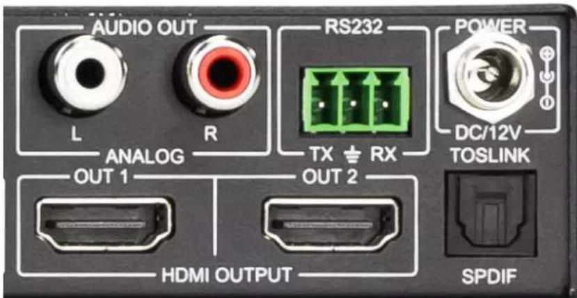
Balanced 5 pin 2Ch and Toslink Audio Port /SPDIF:
The SPDIF Toslink port supports up to 5.1 Ch Digital audio the L/R Analog audio supports 2 Ch audio only. This means in order for these ports to function the sources must be set to 2 Ch PCM, this unit does NOT down mix the audio (see AC-AXION-8 for downmixing matrix). To get more than 2 Channels you will want to use the SPDIF port.
Troubleshooting
- Verify Power - Check that the power supply is properly connected and on an active circuit. - Verify Connections - Check that all cables are properly connected.
• IR Issues - Verify correct connections - Page(s) 30
- Lights indicate everything is good but still not getting a picture, this may be a bandwidth limitation. See Bandwith Chart below to verify the signal is not exceeding the bandwidth of the Extender kit, some can be limited to 10.2Gbps.
Bandwith Chart
| TYPE | RESOLUTION | FRAME RATE (FPS) | COLOUR COMPRESSION | DEEP COLOUR BIT DEPTH | HDR | WIDE COLOR GAMUT (BT2020) | HDMI VERSION | DATA RATE | AUHD SERIES |
| HD | 1920x1080 | 24 | 4:2:2 | 8 BIT | NO | NO | 1.4 | 0.75 GBPS | YES |
| HD | 1920x1080 | 60 | 4:2:2 | 8 BIT | NO | NO | 1.4 | 4.45 GBPS | YES |
| HD | 1920x1080 | 60 | 4:4:4 | 16 BIT | NO | NO | 1.4 | 5.91 GBPS | YES |
| UHD | 3840x2160 | 24 | 4:2:0 | 8 BIT | NO | NO | 1.4 | 8.91 GBPS | YES |
| UHD | 3840x2160 | 24 | 4:4:4 | 8 BIT | NO | NO | 1.4 | 8.91 GBPS | YES |
| 4K | 4096x2160 | 24 | 4:4:4 | 8 BIT | NO | NO | 1.4 | 8.91 GBPS | YES |
| UHD OR 4K | 3840x2160 | 60 | 4:2:0 | 8 BIT | NO | NO | 1.4/2.0 | 8.91 GBPS | YES |
| UHD OR 4K | 3840x2160 | 24 | 4:2:0 | 10 BIT | YES | YES | 2.0(A/B) | 8.91 GBPS | YES |
| UHD OR 4K | 3840x2160 | 24 | 4:2:2 | 12 BIT | YES | YES | 2.0(A/B) | 11.14 GBPS | YES |
| UHD OR 4K | 3840x2160 | 24 | 4:4:4 | 10 BIT | YES | YES | 2.0(A/B) | 11.14 GBPS | YES |
| UHD OR 4K | 3840x2160 | 24 | 4:4:4 | 12 BIT | YES | YES | 2.0(A/B) | 13.37 GBPS | YES |
| UHD OR 4K | 3840x2160 | 60 | 4:2:0 | 10 BIT | YES | YES | 2.0(A/B) | 11.14 GBPS | YES |
| UHD OR 4K | 3840x2160 | 60 | 4:2:0 | 12 BIT | YES | YES | 2.0(A/B) | 13.37 GBPS | YES |
| UHD OR 4K | 3840x2160 | 60 | 4:2:2 | 12 BIT | YES | YES | 2.0(A/B) | 17.82 GBPS | YES |
| UHD OR 4K | 3840x2160 | 60 | 4:4:4 | 8 BIT | YES | YES | 2.0(A/B) | 17.82 GBPS | YES |
Maintenance
To ensure reliable operation of this product as well as protecting the safety of any person using or handling this device while powered, please observe the following instructions.
- Use the power supplies provided. If an alternate supply is required, check voltage, polarity and that it has sufficient power to supply the device it is connected to.
- Do not operate these products outside the specified temperature and humidity range given in the above specifications.
- Ensure there is adequate ventilation to allow this product to operate efficiently.
- Repair of the equipment should only be carried out by qualified professionals as these products contain sensitive components that may be damaged by any mistreatment.
- Only use this product in a dry environment. Do not allow any liquids or harmful chemicals to come into contact with these products.
- Clean this unit with a soft, dry cloth. Never use alcohol, paint thinner or benzene to clean this unit.
Damage Requiring Service
The unit should be serviced by qualified service personnel if:
• The DC power supply cord or AC adaptor has been damaged
- Objects or liquids have gotten into the unit
• The unit has been exposed to rain
• The unit does not operate normally or exhibits a marked change in performance
• The unit has been dropped or the housing damaged
Support
Should you experience any problems while using this product, first, refer to the Troubleshooting section of this manual before contacting Technical Support. When calling, the following information should be provided:
• Product name and model number
• Product serial number
• Details of the issue and any conditions under which the issue is occurring
- Clean this unit with a soft, dry cloth. Never use alcohol, paint thinner or benzene to clean this unit.
Warranty
THE BASICS.
AVPro Edge warranties its products that are purchased from all Authorized AVPro Edge Resellers or direct purchases. Products are guaranteed to be free from manufacturing defects and of sound physical and electronic condition.
AVPro Edge has developed a warranty that anyone can get behind. We really wanted to take all the "red tape" out of a warranty and just make is simple. Our 10 YEAR NO BS warranty hinges on 3 elements.
-
If you are having trouble, call us. We will attempt to troubleshoot your issue over the phone.
-
If it's broke - We'll replace it in advance on our dime. (We'll cover return shipping too.) Repair is an option too, but it's YOUR call.
-
We know you know what you are doing. We will not make you go through unnecessary steps to troubleshoot an extender...
COVERAGE DETAILS.
AVPro Edge will replace or repair (at customer choice) the defective product. If the product is out of stock or on back order it can either be replaced with a comparable product of equal value/feature set (if available) or repair.
Your warranty begins at receipt of product (as confirmed by shipping firm tracking). If tracking information is unavailable for any reason, the warranty will commence 30 ARO (After Receipt of Order). The coverage continues for 10 YEARS.
RED TAPE.
AVPro Edge is not responsible for untraceable purchases or those that were made outside of an authorized channel.
If we conclude that a product or serial number has been tampered with as identified by warranty seal or physical examination the warranty will be void. Additionally, excessive physical damage (beyond normal wear & tear) the warranty may be voided or pro-rated based on the extent of the damage as examined by an AVPro Edge representative.
Damage caused by "acts of God" are not covered. They can include natural disasters, power surges, storms, earthquakes, tornadoes, sink holes, typhoons, tidal waves, hurricanes, or any other uncontrollable event related to nature.
Damage caused by incorrect installation will not be covered. Incorrect power supply, inadequate cooling, improper cabling, inadequate protection, static discharge are examples of this.
Products installed or sold by a third party to AVPro Edge will be serviced by the Authorized AVPro Edge Reseller.
Accessories (IR Cables, RS-232, Power Supplies, etc...) are not included in the warranty. We will make acceptable effort to source and supply replacements for defective accessories at a discounted rate as needed.
OBTAINING AN RMA.
Dealers, Re-sellers, and Installers can request an RMA AVPro Edge Tech Support Rep or their Sales Engineer. Or you may email support@avproedge.com or fill out the general contact form at www.avproedge.com
End users may not request and RMA directly from AVPro Edge and will be referred back to the Dealer, Reseller or Installer.
SHIPPING.
For USA (not including Alaska and Hawaii). Shipping is covered on advanced replacements for FedEx Ground (some expressed exceptions may apply). Defective product return shipping is covered by AVPro Edge using an emailed return label. Item must be returned within 30 days of receipt of replacement product, after 30 days, the customer will be billed. Other return shipping methods will not be covered.
For International (and Alaska and Hawaii) return shipping costs will be the responsibility of the returnee. Once the unit is scanned for return shipping AVPro Edge will ship new unit for replacement.
LEGAL STUFF.
Limitation on Liability
The maximum liability of AVPro Global Holdings LLC under this limited warranty shall not exceed the actual purchase price paid for the product. AVPro Global Holdings LLC is not responsible for direct, special, incidental or consequential damages resulting from any breach of warranty or condition, or under any other legal theory to the maximum extent permitted by law.
Taxes, Duties, VAT, and freight forwarding service charges are not covered or paid for by this warranty.
Obsolescence or incompatibility with newly invented technologies (after manufacture of product) is not covered by this warranty.
Obsolescence is defined as:
"Peripherals are rendered obsolete when current technology does not support product repair or re-manufacture. Obsolete products cannot be remanufactured because advanced technologies supersede original product manufacturer capabilities. Because of performance, price and functionality issues, product redevelopment is not an option."
Discontinued or out of production items will be credited at fair market value towards a current product of equal or comparable capabilities and cost. Fair market value is determined by AVPro Edge.
Exclusive Remedy
To the maximum extent permitted by law, this limited warranty and the remedies set forth above are exclusive and in lieu of all other warranties, remedies and conditions, whether oral or written, express or implied. To the maximum extent permitted by law, AVPro Global Holdings LLC specifically disclaims any and all implied warranties, including, without limitation, warranties of merchantability and fitness for a particular purpose. If AVPro Global Holdings LLC cannot lawfully disclaim or exclude implied warranties under applicable law, then all implied warranties covering this product, including warranties of merchantability and fitness for a particular purpose, shall apply to this product as provided under applicable law.
This warranty supersedes all other warranties, remedies and conditions, whether oral or written, express or implied.
Thank you for choosing AVProEdge!
Please contact us with any questions, we are happily at your service!




AVProEdge 2222 E 52nd St N \~ Sioux Falls, SD 57104
1-877-886-5112 \~ 605-274-6055
support@avproedge.com
- User Manual
- 18Gbps True 4K60 4:4:4, 8x2 Matrix & Auto Switch/AVR Bypass
- AC-MX-82
- Introduction
- Features
- Whats in the box
- Not Included
- Front and Rear Panel Overview
- Initial Setup: WebUI
- DHCP Enabled
- Default Network Settings
- Advanced Setup: WebUI Input Settings
- Advanced Setup: WebUI Output Settings
- Advanced Setup: WebUI Extracted Audio Output Settings
- WebUI: Video Matrix
- WebUI: I/O Config - Input Settings
- WebUI: I/O Config - Input Settings Cont.
- WebUI: I/O Config - Output Settings
- WebUI: I/O Config - Audio Settings
- WebUI: System - IP Control
- WebUI: System - Admin Web Interface
- WebUI: System - User Web Interface
- WebUI: System - Cloud Services
- WebUI: System - Firmware Update Cont.
- WebUI: System - Hardware
- WebUI: Diagnostics - HDMI IN
- WebUI: Diagnostics - HDMI IN Cont.
- WebUI: Diagnostics - HDMI OUT
- WebUI: Console
- Example
- Front Panel Control - Functional Mode Button
- Front Panel Control - Matrix Mode Switching
- Front Panel Control - DA Mode Switching
- Front Panel Control - Audio Output
- Front Panel Control - EDID Management:
- To Change the EDID setting:
- IR Control: IR Remote
- IR Remote Control:
- RS-232 and TCP/IP Control:
- Command List:
- Command List Continued:
- Extracted Audio:
- Setting up Extracted Audio Routing:
- Troubleshooting
- Maintenance
- Damage Requiring Service
- Support
- Warranty
- THE BASICS.
- COVERAGE DETAILS.
- RED TAPE.
- OBTAINING AN RMA.
- SHIPPING.
- LEGAL STUFF.
- Exclusive Remedy
- Thank you for choosing AVProEdge!
- Please contact us with any questions, we are happily at your service!
Марка : AVPro Edge
Модель : AC-MX-82
Категория : Маршрутизатор