
P24W-7 LED - Televizor FUJITSU - Manual de utilizare gratuit
Găsiți gratuit manualul dispozitivului P24W-7 LED FUJITSU în format PDF.

Întrebările utilizatorilor despre P24W-7 LED FUJITSU
0 întrebare despre acest aparat. Răspundeți la cele pe care le cunoașteți sau puneți-vă propria.
Pune o întrebare nouă despre acest aparat
Descărcați instrucțiunile pentru Televizor în format PDF gratuit! Găsiți manualul dvs. P24W-7 LED - FUJITSU și luați din nou în mână dispozitivul dvs. electronic. Pe această pagină sunt publicate toate documentele necesare pentru utilizarea dispozitivului dvs. P24W-7 LED mărcii FUJITSU.
MANUAL DE UTILIZARE P24W-7 LED FUJITSU
FUJITSU Display P24W-7 LED

Congratulations on your purchase of an innovative product from Fujitsu.
Latest information about our products, tips, updates etc. can be found on the Internet at: "http://www.fujitsu.com/fts/"
You can find driver updates at: "http://support.ts.fujitsu.com/download"
Should you have any technical questions, please contact:
- our Hotline/Service Desk (see the Service Desk list or visit: "http://support.ts.fujitsu.com/contact/servicedesk")
- Your sales partner
- Your sales office
We hope you enjoy working with your new Fujitsu system!
FUJITSU
Published by / Contact address in the EU
Fujitsu Technology Solutions GmbH
Mies-van-der-Rohe-Straße 8
80807 Munich, Germany
"http://www.fujitsu.com/fts/"
Copyright
© Fujitsu Technology Solutions GmbH 2014. All rights reserved.
Publication Date
03/2014
Order No.: A26361-K1498-Z320-1-7619, edition 1
FUJITSU Display P24W-7 LED
Operating Manual
Your LCD screen... 5
Important notes 7
Getting started 11
Operation 22
Notes on ergonomic colour adjustment 35
Troubleshooting 36
Explanatory information about
standard ISO 9241-307 38
Technical specification 39
Remarks
Notes on the product description meet the design requirements of Fujitsu and are provided for the purposes of comparison. The actual results may differ due to several factors. Subject to technical changes without prior notification. Fujitsu accepts no responsibility for technical or editorial mistakes or omissions.
Trademarks
Fujitsu and the Fujitsu logo are registered trademarks of Fujitsu Limited or its subsidiaries in the United States and other countries.
Microsoft and Windows are trademarks or registered trademarks of the Microsoft Corporation in the United States and/or other countries.
VESA, DDC and DPMS are registered trademarks of Video Electronics Standards Association.
All other trademarks specified here are the property of their respective owners.
Copyright
No part of this publication may be copied, reproduced or translated without the prior written consent of Fujitsu.
No part of this publication may be saved or transmitted by any electronic means without the written consent of Fujitsu.
Contents
Your LCD screen.... 5
Target group 5
Further information 6
Notational conventions 6
Important notes 7
Safety instructions 7
Power cable 8
Transporting the device 8
Cleaning the device 9
CE marking 9
Power management 9
Disposal and recycling 10
Getting started 11
Unpacking and checking the delivery 11
Setting up the device 12
Setting up an ergonomic video workstation 12
Mounting the monitor base 14
Adjusting height 15
Adjusting the inclination 15
Adjusting the rotation 15
Removing monitor base 16
Connecting the device 17
Connecting cables to the computer 18
MHL (Mobile High Definition Link) 19
Operation 22
Switching the device on and off 22
Notes on power management 24
Notes on the ambient light sensor and presence sensor 25
Changing the monitor settings 26
Changing the monitor settings with the buttons of the control panel 26
Changing the monitor settings using the OSD menu 29
OSD menu functions 30
Adjusting the brightness and contrast 31
Selecting the application mode 31
Setting screen display 32
Adjusting the volume 32
Setting colour temperature and colours 33
Setting the OSD menu 33
Advanced setting functions 34
Displaying information 34
Notes on ergonomic colour adjustment 35
Troubleshooting 36
Explanatory information about standard ISO 9241-307 38
Technical specification 39
VESA-DDC-compatible VGA interface 40
Preset operating modes 40
Most frequent operating modes 40
Video/TV operating modes using DisplayPort and HDMI 41
SUB D port 41
DVI-D port 42
DisplayPort socket 43
HDMI port 44
Your LCD screen...
has a whole range of useful features and functions, e.g.:
• TFT display (Thin Film Transistor; active matrix)
• minimal space requirements thanks to slim casing
• optimum ergonomic characteristics (totally distortion-free, excellent picture definition and colour purity right into the corners)
• high degree of brightness and good contrast
• maximum resolution of 1920 x 1200
• presentation of up to 16.7 million colours (in conjunction with an appropriate display adapter)
• automatic scanning of horizontal frequencies from 30 to 82 kHz and refresh rates (vertical frequencies) from 48 to 76 Hz (absolutely flicker-free)
• digital screen controller with microprocessor for storing 32 different display modes
- freely adjustable colour alignment for matching the screen colours to the colours of various input and output devices
• convenient operation via integrated OSD (On-Screen-display) menu
• VESA-DDC compatibility
- VESA-FPMPMI compatibility (Flat Panel Monitor Physical Mounting Interface) – Mounting device for swivel arm or similar accessory
• Plug&Play capability
• digital video inputs (DVI, HDMI and DisplayPort) with HDCP
• power management for reducing power consumption when the computer is not in use
• Compliance with the recommendations according to TCO 6.0
• the monitor fulfills all GS ("Geprüfte Sicherheit", Certified Security) requirements.
This operating manual contains important information you require to start up and run your LCD monitor.
A display adapter (graphics card) with VGA interface or a digital display adapter with DVI interface or video signal source with DisplayPort interface is required to control the LCD monitor. The monitor processes the data supplied to it by the display adapter. The display adapter or the associated driver software is responsible for setting the modes (resolution and refresh rate).
When putting the monitor into operation for the first time, the screen display should be optimally adapted to the display adapter used and adjusted in accordance with your needs (see chapter "Changing the monitor settings", Page 26).
Target group
You don't need to be an "expert" to perform the operations described here.
Nonetheless, it is important to always observe the safety notes given in the operating instructions for the computer and in this manual.
In the event of any problems, please contact your sales office or our Service Desk.
Further information
Details of how you set the resolution and refresh rate are provided in the documentation for your display adapter and the associated driver software.
For ergonomic reasons, we recommend a screen resolution of 1920 x 1200 pixels.
Because of the technology used (active matrix) an LCD monitor provides a totally flicker-free picture even with a refresh rate of 60 Hz.
Notational conventions
| Pay particular attention to text marked with this symbol. Failure to observe these warnings could pose a risk to health, damage the device or lead to loss of data. The warranty will be invalidated if the device becomes defective through failure to observe these warnings. | |
| Indicates important information for the proper use of the device. | |
| ▶ | Indicates an activity that must be performed |
| ↳ | Indicates a result |
| This font | indicates data entered using the keyboard in a program dialogue or at the command line, e.g. your password (Name123) or a command used to start a program (start.exe) |
| This font | indicates information that is displayed on the screen by a program, e.g.: Installation is complete. |
| This font | indicates• terms and texts used in a software interface, e.g.: Click on Save• names of programs or files, e.g. Windows or setup.exe. |
| "This font" | indicates• cross-references to another section, e.g. "Safety information"• cross-references to an external source, e.g. a web address: For more information, go to "http://www.fujitsu.com/fts/"• Names of CDs, DVDs and titles or designations of other materials, e.g.: "CD/DVD Drivers & Utilities" or "Safety" Manual |
| Key | indicates a button on the monitor, e.g: MENU |
| This font | indicates terms and texts that are emphasised or highlighted, e.g.: Do not switch off the device |
Important notes
In this chapter you will find information regarding safety which it is essential to take note of when working with your device.
Safety instructions
This device complies with the relevant safety regulations for data processing equipment, including electronic office machines for use in an office environment. If you have any questions about whether the device can be used in the intended environment, please contact your sales office or our Service Desk.
- The display surface of the device is sensitive to pressure and scratches. You should therefore be careful with the display surface in order to avoid lasting damage (scratches).
- If the device is brought into the installation site from a cold environment, condensation can form. Before operating the device, wait until it is absolutely dry and has reached approximately the same temperature as the installation site.
- When installing and operating the device, please observe the notes on environmental conditions in Chapter "Technical specification", Page 39 as well as the instructions in Chapter "Setting up an ergonomic video workstation", Page 12.
• To ensure sufficient ventilation, the air inlet and outlet openings of the device must be kept clear.
- The device automatically sets itself to the correct voltage within the range from 100 V to 240 V. Make sure that the local mains voltage is neither higher nor lower than this range.
- Ensure that the power socket on the device and the mains outlet are freely accessible.
- The ON/OFF button does not disconnect the monitor from the mains voltage. To completely disconnect from the mains voltage, remove the power plug from the power socket.
• The device is equipped with a power cable that complies with safety standards.
• Use the supplied power cable only.
- Lay the cables in such a way that they do not create a hazard (danger of tripping) and cannot be damaged. When connecting the device, observe the relevant notes in chapter "Connecting the device", Page 17.
• No data transfer cables should be connected or disconnected during a thunderstorm.
• Make sure that no objects (e.g. jewellery chains, paper clips, etc.) or liquids get inside the device (danger of electric shock, short circuit).
- The device is not waterproof! Never immerse the device in water and protect it from spray water (rain, sea water).
- In an emergency (e.g. damaged casing, operation controls or cables, penetration of liquids or foreign matter), switch off the device, disconnect the power plug and contact your sales outlet or our Service Desk.
- Repairs to the device must only be performed by qualified technicians. Unauthorised opening and incorrect repair may greatly endanger the user (electric shock, fire risk).
- Only use the screen resolution settings and refresh rates specified in Chapter "Technical specification", Page 39. Otherwise you may damage the device. If you are in any doubt, contact your sales outlet or our Service Desk.
- Use a screen saver with moving images and activate the power management for your monitor to prevent still images from "burning in".
- If you operate the device with the swivel arm or a similar accessory, it must not be turned through 180°.
- The device may only be operated in wide format (0° landscape mode) and high format (90° portrait mode). The buttons are located at the bottom in the middle of the monitor in wide format (0° landscape mode) and on the left-hand side of the monitor in high format (90° portrait mode).
- Store this manual close to the device. If you pass the device on to third parties, you should pass this manual on with it.
• We recommend that you place your device on a durable, non-slip surface. In view of the many different finishes and varnishes used on furniture, it is possible that the feet of the device may mark the surface they stand on. - Avoid using high volumes for a long period of time, to prevent causing damage to your hearing.
- Warning about excessive sound pressure from headphones: Excessive sound pressure from headphones can cause a loss of hearing. Setting the equalizer to the maximum value increases the headphones output voltage and thus increases the sound pressure.
Power cable
Use the supplied power cable only.
Use the following guidelines if it is necessary to replace the original cable set.
• The female/male receptacles of the cord set must meet IEC60320/CEE-22 requirements.
- The cable has to be HAR-certified or VDE-certified. The mark HAR or VDE will appear on the outer sheath.
- For devices which are mounted on a desk or table, type SVT or SJT cable sets may be used. For devices which sit on the floor, only SJT type cable sets may be used.
• The cable set must be selected according to the rated current for your device.
• If necessary, replace the original power cable with a regular grounded 3-core mains lead.
Transporting the device

Transport all parts separately in their original packaging or in a packaging which protects them from knocks and jolts, to the new site.
Do not unpack them until all transportation manoeuvres are completed.
If the device is brought from a cold environment into the room where it will be used, condensation may occur. Before operating the device, wait until it is absolutely dry and has reached approximately the same temperature as the installation site.
Cleaning the device

Switch off the device and unplug the power plug.
Do not clean any interior parts yourself, leave this job to a service technician.
Do not use any cleaning agents that contain abrasives or may corrode plastic.
Ensure that no liquid enters the device.
The display surface of the device is sensitive to pressure and scratches. Clean it only using a soft, slightly moistened cloth.
The surface of the casing can be cleaned with a dry cloth. If particularly dirty, use a cloth that has been moistened in mild domestic detergent and then carefully wrung out.
CE marking
The shipped version of this device complies with the requirements of European Union directives 2004/108/EC "Electromagnetic compatibility", 2006/95/EC "Low voltage directive" and 2009/125/EC "Ecodesign Directive".
Power management
The Fujitsu LCD monitor is equipped with a power management system which reduces the power draw in 0 W energy saving mode to less than 0 W (for VGA and DVI).
Disposal and recycling
This device has been manufactured as far as possible from materials which can be recycled or disposed of in such a way that the environment is not damaged. The device may be taken back after use to be reused or recycled, provided that it is returned in a condition that befits its intended use. Any components not reclaimed will be disposed of in an environmentally acceptable manner.
The device must be disposed of in accordance with the local regulations for disposal of special waste.
If you have any questions on disposal, please contact your local sales office or our Service Desk, or contact one of the following directly:
| Germany | Belgium | Switzerland |
| Fujitsu Technology Solutions GmbHRemarketing and RecyclingD-33106 PaderbornTel.: +49 5251 / 81 80 10Fax: +49 5251 / 81 80 15"http://fujitsu.com/fts/remarketing" | RECUPELBoulevard Reyers, 80B-1030 BrusselsTel.: +32 2 / 706 86 16Fax: +32 2 / 706 86 13E-Mail: info@recupel.be"http://www.recupel.be" | SWICOSchweizerischerWirtschaftsverbandder Informations-, Kommunikations- und OrganisationstechnikA list of the SWICO acceptance locations can be found at:"http://www.swico.ch" |
| Asia | USA | |
| Taiwan:Environmental Protection AdministrationExecutive Yuan R.O.C."http://recycle.epa.gov.tw" | Fujitsu America, Inc.1250E. Arques AvenueSunnyvale, CA 94085 U.S.A.Phone No.: (408) 746-6000 |
You can also find more information on this at "http://www.fujitsu.com/fts/about/fts/environment-care/".
Getting started
Unpacking and checking the delivery

The display surface of the device is sensitive to pressure and scratches.
Always hold the device by the casing!
The complete device package includes:
- one monitor
• one DisplayPort cable - one DVI cable
- one VGA cable
- one USB cable
- one audio cable
- one power cable
• one CD with software and documentation
• one Warranty Booklet
• one "Quick Start Guide" flyer
• one "Safety/Regulations" manual
▶ Unpack all the individual parts.
▶ Check the contents of the package for any visible damage caused during transport.
▶ Check whether the delivery conforms to the details in the delivery note.
▶ Should you discover that the delivery does not correspond to the delivery note, notify your local sales outlet immediately.

Do not discard the original packing material of the devices. You may need the packaging in the future if you need to transport your device.
Setting up the device

To ensure sufficient ventilation, the air inlet and outlet openings of the device must be kept clear.
Setting up an ergonomic video workstation
flowchart
graph TD
    A["1"] --> B["Component 1"]
    A --> C["Component 2"]
    A --> D["Component 3"]
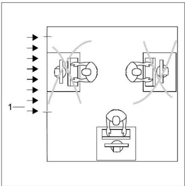
▶ Do not position the video workstation opposite a window (1).
natural_image
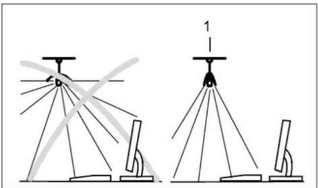
Diagram showing two configurations of a surveying instrument with multiple tripod supports and a scale, no text or symbols present.▶ Position the monitor outside the reach of a light source (1).
natural_image
Line drawing of a person sitting at a desk using a computer (no text or symbols present)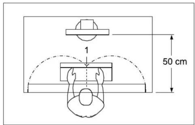
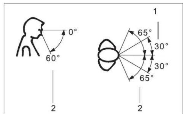
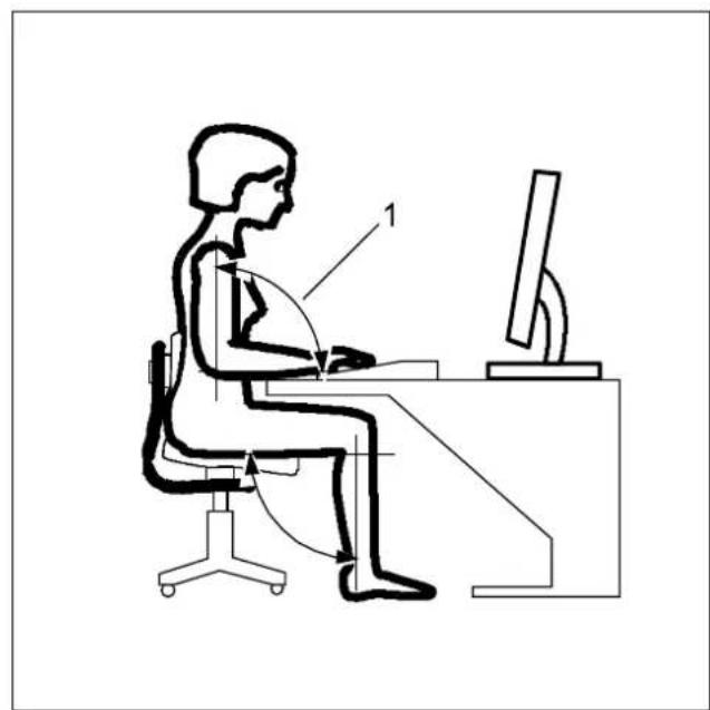
▶ Position the keyboard where it is easiest to reach (1).
▶ Position the monitor so that the eye distance to the screen (1) is around 50 cm.
▶ Position the monitor for optimum viewing (1). The monitor should under no circumstances fall outside the permissible viewing space (2).

Depending on the situation, it may be advisable to use a swivel arm or a similar accessory (VESA FPMPMI), which are available from specialist dealers. For this purpose the monitor base must be removed beforehand as described in chapter "Removing monitor base", Page 16.
Mounting the monitor base

Do not remove the retaining splint until you have secured the base plate on the monitor and moved it into the operating position.
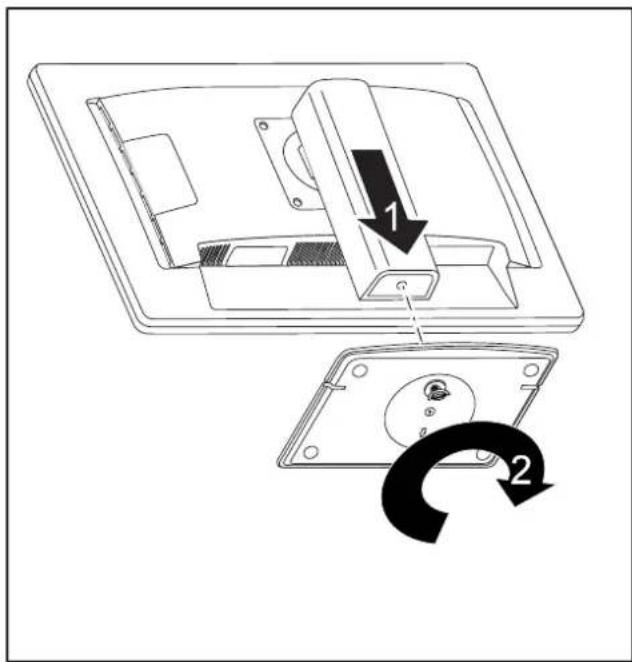
▶ Insert the base plate on the foot (1).
▶ Secure the base plate with the screw (2).
▶ Place the monitor in the operating position.
Adjusting height

The height adjustment is fixed in the transport position.
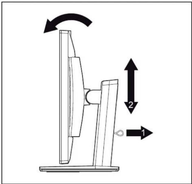
▶ To free the fixing, remove the locking pin on the flange (1).
→ The height of the monitor can be adjusted by approximately 130 mm.
▶ Grasp the monitor with both hands on the right and left edge of the casing and move it up or down (2).
Adjusting the inclination
The inclination of the monitor can be adjusted by -3^ (forwards) and +35^ (backwards) from its vertical position.
▶ Hold the monitor with both hands on the left and right sides of the casing and move it to the desired angle.
Adjusting the rotation
The monitor can be rotated by ±170°.
▶ Grasp the monitor with both hands on the right and left edge of the casing and turn it to the desired position.
Removing monitor base
Before you can use a swivel arm or a similar accessory, you must remove the monitor base.

The display surface is susceptible to scratching!
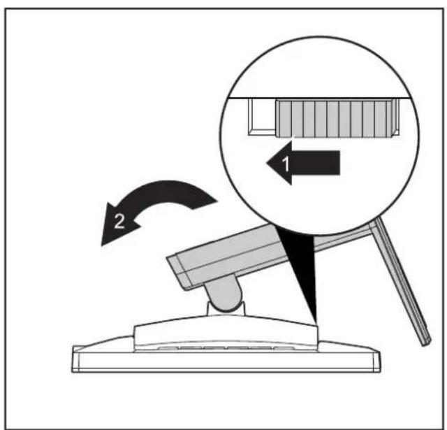
▶ Switch off the monitor and pull the power plug out of the power socket.
▶ Lay the monitor on its face on a soft surface.
▶ Disconnect all cables.
▶ Release the base stand by moving the slider in the direction of the arrow (1) and hold it while lifting the complete base stand up (2).
→ You can now mount a swivel arm or a similar accessory in accordance with VESA FPMPMI using a hole spacing of 100 mm.

For instructions on how to mount the swivel arm or a similar accessory, please see the documentation for the swivel arm or similar accessory.
Connecting the device

Please observe the safety information in "Important notes", Page 7.
CE conformance and optimum picture quality are guaranteed only if you use the data cables supplied.
▶ Switch off the monitor and the computer.
▶ Disconnect the power plug from the computer.
Connecting cables to the monitor
The supplied data cables have two 15-pin D-SUB connectors or two 24-pin DVI connectors or two 20-pin DisplayPort connectors for connection to the monitor and to the computer.
Information on the computer connections and interfaces is contained in the operating manual for the computer.
natural_image
Technical line drawing of a mechanical assembly with no visible text or symbols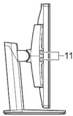
natural_image
Technical line drawing of a mechanical component with a labeled part (11), no readable text or symbols present.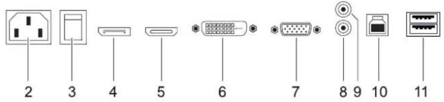
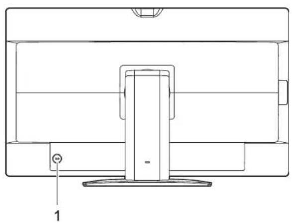
1 = Security slot for "Security Lock"
2 = Power connector
3 = 0 W switch
4 = DisplayPort socket
5 = HDMI socket
6 = DVI-D socket (DVI)
7 = D-SUB socket (VGA)
8 = AUDIO-IN socket
9 = AUDIO-OUT socket
10 = USB 3.0 (Upstream)
11 = USB 3.0 (Downstream)
▶ Select the appropriate data cable for your computer.
▶ Connect one of the data cable connectors to the DVI-D or DisplayPort socket on the monitor and secure the DVI-D plug-in connection by tightening the safety screws.

If you use a DisplayPort cable, you must switch the 0 W switch to the BASIC position. If you use a VGA, HDMI or DVI Dual Link data cable, you can switch the 0 W switch to the ECO "0" position to activate the 0 W energy saving mode when the PC is switched off.
The monitor automatically detects the input (VGA, HDMI, DVI, DisplayPort) when only one signal source is connected.

Note that the 0 W function cannot be guaranteed when using any kind of signal cable adaptor.
▶ Insert one connector of the audio line in the AUDIO IN (8) socket on the monitor and make sure it is properly engaged.
▶ Plug the power cable supplied into the power connector of the monitor.
▶ Plug the supplied USB 3.0 cable into the USB 3.0 (Upstream) socket (10) and the other end of the cable into a USB 3.0 socket on the computer.

Connect the USB keyboard and USB mouse directly to the PC, as the USB connector socket of the monitor is switched off in energy-saving mode.

A lock (Security Lock) can be mounted in the security slot to protect the monitor against theft. A Security lock is not supplied with the monitor.
Connecting cables to the computer
Information on the computer connections and interfaces is contained in the operating manual for your computer.
▶ Connect the data cable to the (active) monitor port on the computer and secure the plug-in connection by tightening the safety screws.
▶ Insert the other plug of the audio cable in the audio output of the computer.
▶ Plug the power connector of the monitor into a properly grounded mains outlet.
▶ Plug the power connector of the computer into a properly grounded mains outlet.

If your computer has two monitor ports ("onboard" screen controller and separate graphics card), the monitor port for the separate graphics card is active as standard.
MHL (Mobile High Definition Link)

MHL is an HD video and digital audio interface optimized for connecting mobile phones and portable devices to HDTVs, displays and other home entertainment products.
It features a single cable with a 5-pin interface able to support up to 1080p HD video and digital audio while simultaneously providing power to the mobile device, and utilizing established connectors.
This monitor uses the MHL specification (version 1.2) and has the following useful functions:
• HD Video and Digital Sound
Users can play HD videos with an image quality of up to 1080p/60 and digital sound of up to 192 kHz from their mobile device.
• Use of established connector types (micro-USB)
The MHL specification allows manufacturers to use widely available connector types that are already used in mobile and CE systems.
• Low Pin Count Interface
HD video and digital sound are transmitted via a single five-pin interface, over which control and power are also transmitted at the same time. This means manufacturers can keep their mobile devices small and keep their implementation costs down.
• Power supply for the mobile device
MHL makes it possible to operate the device in MHL mode, whereby the monitor supplies 5 V and 500 mA of power at the same time. This means, for example, that an entire film can be played on this monitor from a mobile telephone without the device's battery getting low, so the mobile phone can still be used later for making telephone calls or sending emails.
- Encryption
MHL supports High-Bandwidth Digital Content Protection (HDCP) to protect high-quality digital films, television programmes and sound files against unauthorised access and copying.
Using MHL

To use the MHL function, you need a MHL-certified mobile device. You can consult the website of your mobile device's manufacturer to check whether your mobile device is MHL-certified. A list of MHL-certified devices is available on the official MHL website ("http://www.meetmhl.com").
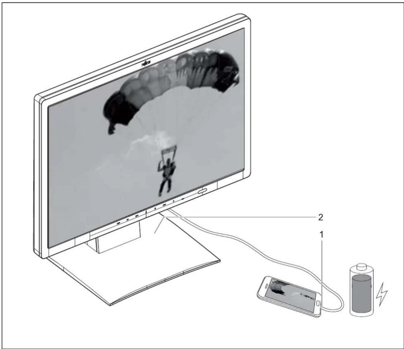
▶ Connect the micro-USB interface of the mobile device (1) to the HDMI interface on the monitor (2) using the MHL cable.
▶ Press the INPUT button and select HDMI as the input source if the screen is displaying another active image from another input source (e.g. VGA).
→ The MHL screen of the mobile device will be displayed.

It might take a few seconds for the MHL output of the mobile device to be displayed. This can also depend on the mobile device. If the mobile device does not support MHL, no image will be displayed on the screen.

To use the MHL function, the latest software version must be installed on the mobile device.
On some mobile devices, the MHL function may not be available depending on the devices' performance or functionality.
Since the display size of the product is larger than those of mobile devices, the picture quality may degrade.
This product is officially MHL-certified. If you encounter problems when using the MHL function, please contact the manufacturer of the mobile device.
The picture quality may degrade if content with a low resolution (imported from the mobile device) is played back on the product.
Operation
Switching the device on and off
Using the buttons
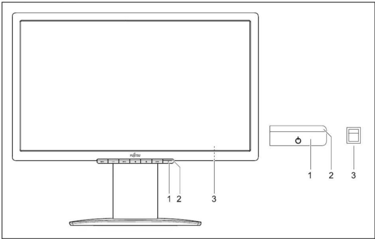
1 = ON/OFF button
2 = Power indicator
3 = 0 W switch (on the rear of the monitor)
Using the touch sensors
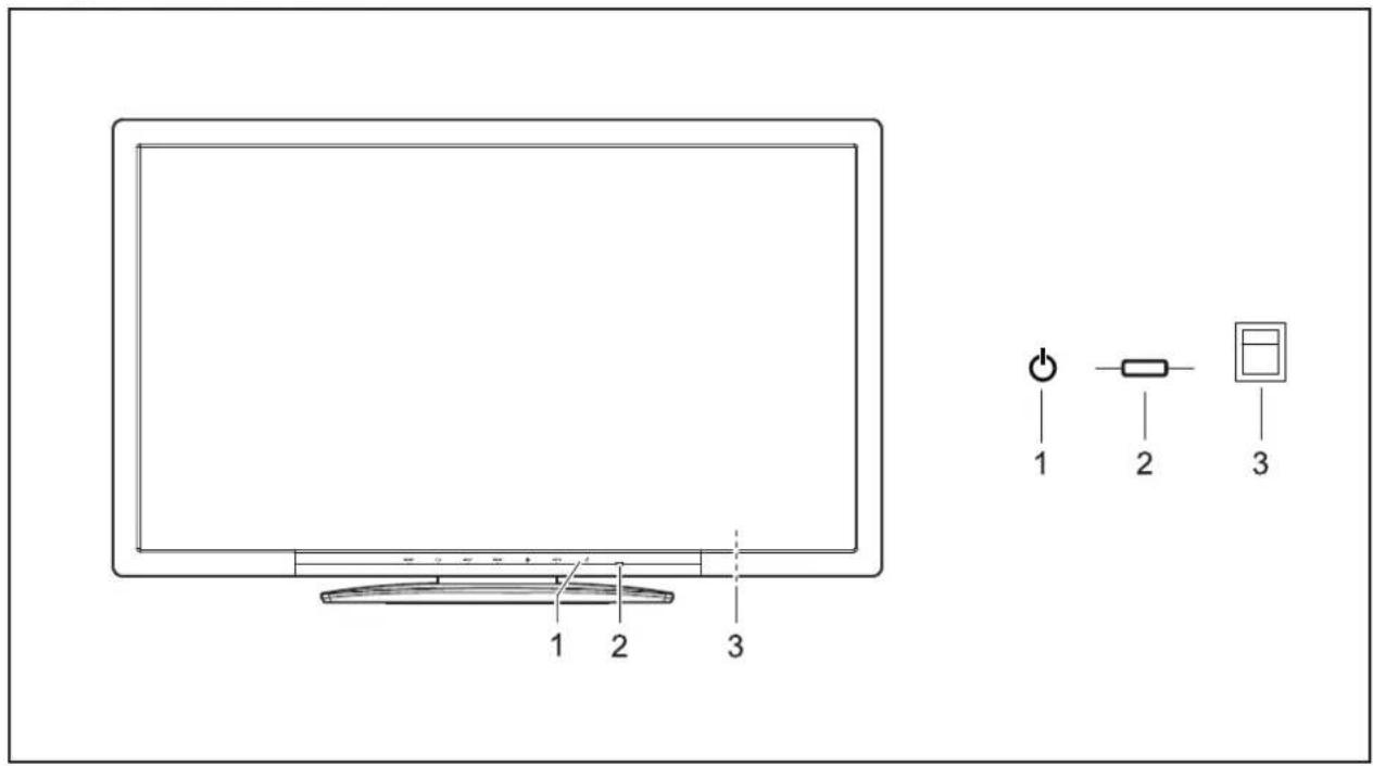
1 = On/Off touch sensor
3 = 0 W switch (on the rear of the monitor)
2 = Power supply indicator
The colour of the LED indicator changes as follows:
| LED indicator | Status |
| blue | Monitor and computer are switched on (normal mode). |
| green | Monitor and computer are switched on (ECO mode). |
| orange | Monitor is not receiving a video signal or is in BASIC power saving mode. |
| does not light up | Monitor is switched off (or is in 0 W energy-saving mode). |

The "0" setting for the 0 W switch (3) on the rear activates the ECO energy-saving mode (0 W operating mode); the "I" switch setting switches to BASIC energy-saving mode (<1 W). This setting is only required for the DisplayPort cable, but it can also be required for VGA or DVI on many PCs if the screen stays dark in 0 W operating mode.
▶ Switch the device on using the ON/OFF button (1) or the ON/OFF touch sensor (1).
Notes on power management
If your computer is equipped with power management (power saving mode), the monitor can fully support this function. The monitor thereby distinguishes between the individual power saving modes of the computer (standby mode, suspend mode and OFF mode).
| Stage | Operation | Power-saving mode (0 W switch) | ||
| Normal | ECO | ECO (0) | BASIC (I) | |
| Power supply indicator | Lights up blue | Lit green | is unlit | illuminated orange |
| Display | Max. brightness | typ. 200 cd/m2 | unlit | orange |
| Typical power consumption (without USB and audio) | 25 W | 20 W | reduced to 0 W (only for VGA, DVI and HDMI) | reduced to < 0.5 W (for all input sources) |
If the computer detects inactivity (no input) it sends an appropriate signal to the monitor to reduce the power consumption (power saving mode). The power indicator of the monitor changes colour to show the change in status. The ECO operating mode and BASIC power-saving mode are the preset factory defaults.
Once an input is made at the computer the screen contents are restored.

For detailed information on how energy-saving mode operates, please refer to the operating manual or technical manual of the computer.
Notes on the ambient light sensor and presence sensor
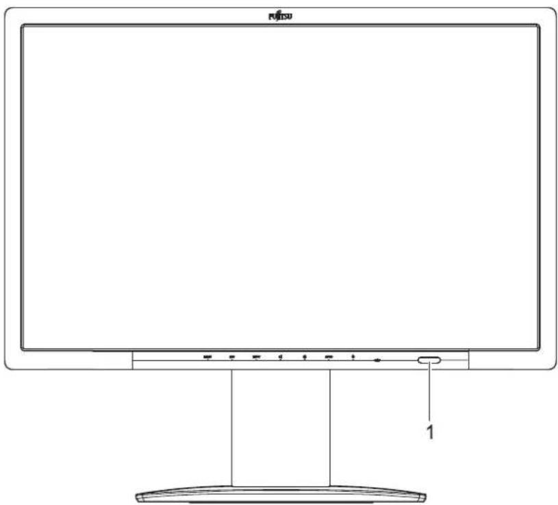
1 = Ambient light and presence sensor
| Sensor | Description |
| Ambient light sensor | If the Auto Brightness function is activated, the ambient light sensor is used for optimum adjustment of the background lighting to the light conditions of the working environment. |
| Presence sensor | If the Presence Sensor function is activated, the presence sensor is used to reduce the background lighting to a minimum if no object is detected within the specified distance for 10 seconds.After 30 seconds with no object present, the background lighting is switched off. |

In order to achieve the best possible results with the presence sensor, observe the following:
• Make certain that no objects are located in the immediate proximity of the presence sensor.
- Recommendation: Adjust your distance to the monitor in the OSD menu. You will find more information on this in chapter "Advanced setting functions", Page 34.
- Depending on the colour of your clothes, the distance detected may deviate from the setting.
- When the presence sensor is activated, the power consumption during operation is increased minimally.
Changing the monitor settings
When putting the monitor into operation for the first time, the screen display should be optimally adapted to the display adapter used.
Changing the monitor settings with the buttons of the control panel

Depending on the model, the control panel will either have buttons or touch sensors. In the following sections, only buttons will be mentioned. However, the text also applies to models with touch sensors.
The buttons on the control panel have multiple functions. When the OSD menu is active, the current meaning of the buttons is shown directly over the buttons on the edge of the screen.
The display (softkey icon) over the buttons varies depending on the sub-menu chosen.
| Key | Function |
| MENU | Call up OSD menu |
| ECO | Activate/deactivate ECO operating mode |
| INPUT | Select input signal (digital/analog) |
| Adjust volume | |
| Adjust brightness | |
| AUTO | Perform auto-adjustment of the monitor with analog input |
| Monitor: switching on/off |
| Softkey icon | Function |
| ↑ | Selecting the next menu item (sub-menu) |
| ↓ | Selecting the previous menu item (sub-menu) |
| → | Opening the selected sub-menuGoing to the next setting |
| ← | Going to the previous setting |
| — | Decreasing the set value |
| + | Increasing the set value |
| √ | Accepting the applied settings and returning to main menu |
| ⇐ | Cancelling the applied settings and returning to main menu |
| × | Exiting OSD menu |
| ¼ | Loudspeaker: switching off/on |

When the OSD menu is not activated, you can apply the following settings directly:
Select OSD language
When an OSD menu button is activated for the first time, the language selection window will appear:
▶ Press the ↑ button or the ↓ button to choose the desired language.
▶ Press the √ button to confirm.
After selecting the OSD language for the first time, you can change it at any time in the OSD.
Activate/deactivate ECO operating mode

The power consumption of the device can be decreased by reducing the brightness of the picture.
▶ Press the ECO button to switch the ECO operating mode on or off.
The message ECO Mode on or ECO Mode off is displayed.
If the ECO operating mode is activated, the following OSD settings are changed:
Mode Office
Color 6500 K
Brightness reduced
After the ECO operating mode is switched off, the brightness previously set by the user is restored.
Selecting the input signal
▶ Press the INPUT button to open the Input select setting window.
▶ Press the ↑ button or the ↓ button to select the desired monitor connection (VGA, DVI, HDMI or DP).
▶ Press the √ button to confirm or the ← button to cancel.

This setting window can also be called up when the OSD menu is locked.
Adjusting the volume
▶ Press the 📋 button to open the Volume setting window.
▶ Press the — button or the + button to set the desired volume for the built-in speakers.
▶ Press the ✕ button to activate/deactivate the mute function.
▶ Press the × button to close the menu.
Adjusting the brightness
▶ Press the ⚙ button to open the Brightness setting window.
▶ Press the — button or the + button to set the desired brightness.
▶ Press the × button to close the menu.
Performing auto-adjustment of the monitor

This function is only intended for analogue image transmission (VGA).
▶ Press the AUTO button for about 1 second.
→ The Auto Processing message appears.
Picture quality and position are set to optimum values for your system.
Locking the OSD menu
The OSD menu can be locked to prevent accidental or unauthorised changes to the monitor settings.
▶ Press and hold the MENU button for a few seconds while you switch on the monitor with the ON/OFF switch or the ON/OFF touch sensor.
→ The message OSD locked / unlocked is displayed.

Please proceed in the same manner to release the locked OSD menu again.
Locking the ON/OFF button or ON/OFF touch sensor
The ON/OFF button or ON/OFF touch sensor can be locked to prevent accidental or unauthorised changes to the screen settings.
▶ Press the ECO button and INPUT button at the same time for a few seconds.
→ The message Power button locked / unlocked is displayed.
In order to unlock the ON/OFF button or ON/OFF touch sensor, do the same again.
Changing the monitor settings using the OSD menu
With the buttons on the control panel, you can call up and use the integrated OSD (On-Screen Display) menu.

The English menu names are used in the following description (default setting).
The OSD menu of your device may differ in several ways from the functional scope described.

The softkey icons may deviate from those shown here.
▶ Press the MENU button to activate the OSD menu.
→ The OSD menu appears, with menu items for the setting functions.
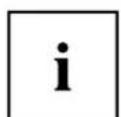
The first menu item (Brightness/Contrast) is highlighted and the associated functions are visible in the right-hand menu field.
▶ Press the ↑ button or ↓ button to highlight another icon (e.g. Image).
▶ Press the → button to select the highlighted icon.
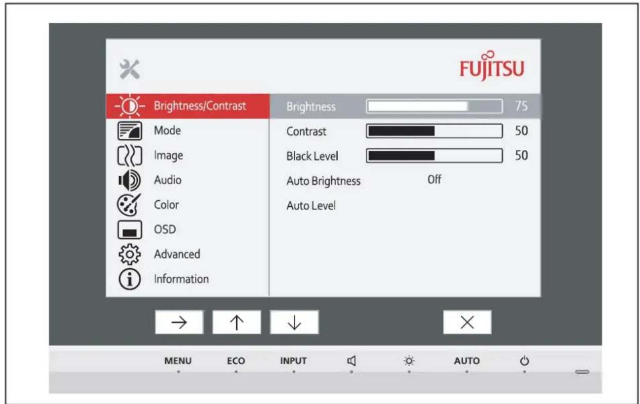
→ The Image setting window will be displayed.
▶ Press the × button to close the OSD menu.
▶ Press the ↑ button or ↓ button to highlight another function.
▶ Press the + button or the — button to change the setting.
▶ Press the √ button to save the change or the ↩ button to quit the function without making a change.

If you wish to change other settings, select the corresponding function from the OSD main menu. All the settings options in the main menu are described below.
OSD menu functions

The OSD menu for analogue monitor operation is described below. During digital operation some functions are not available, as they are not required due to the digital transmission technology used.
Adjusting the brightness and contrast
| Call up the Brightness/Contrast setting window | |
| Brightness | Set the brightness of the displayWith this function you change the brightness of the background lighting.You can see whether the ECO operating mode is active under the bar for displaying the brightness setting. |
| Contrast | Set the contrast of the displayWith this function you modify the contrast of bright colour tones. |
| Black level | Set the brightness of the displayWith this function you modify the contrast of dark colour tones. |
| ACR | Enable/disable dynamic contrastThis function improves the contrast by automatically controlling the background lighting in relation to the image being displayed.This setting can only be configured in Video application mode. |
| Auto Brightness | Automatic brightness controlThis function is used to automatically control the brightness of the background lighting using the ambient light sensor.This setting can only be configured in devices with an ambient light sensor.On = The brightness is adjusted according to the ambient brightnessOff = The brightness is adjusted manually by the user |
| Auto level | Adjust the signal levelWith this function you can automatically set the contrast.The function is executed using →. |

If the contrast is set too high, bright surfaces can no longer be distinguished from very bright surfaces. If the contrast is set too low, the maximum brightness will not be achieved.
Selecting the application mode
| Call up the Mode setting window | |
| D mode | DICOM simulation settings (the settings for Color and ACR are locked: Color = 7500K, ACR = off) |
| sRGB | Predefined settings for sRGB (reduced brightness) |
| Office | Office settings (the settings for Color and sharpness can be adjusted) |
| Photo | Predefined settings for Photo (Color, Sharpness, Saturation) |
| Video | Predefined settings for Video (Color, Sharpness, Saturation, ACR) |
Setting screen display
| [IMAGE] | Open the Image window |
| Phase | Eliminate picture disturbanceWith this function you fine-tune your monitor to eliminate picture disturbance. |
| Clock | Set synchronisationWith this function you adjust the picture width to eliminate vertical picture disturbances. |
| H-Position | Adjust the horizontal positionWith this function you move the picture to the left or to the right. |
| V-Position | Adjust the vertical positionWith this function you move the picture up or down. |
| Sharpness | Adjust the sharpness of the picture for the Photo and Video modes. |
| Saturation | Setting colour saturationThis setting only applies for devices with YUV output (e.g. BluRay players). |
| Hue | Setting the colour toneThis setting only applies for devices with YUV output (e.g. BluRay players). |
| Expansion | Adjust the picture sizeFull screen = selection of full screen modeKeep aspect = maximum picture size without distortion (only for PC image)1:1 = image with no enlargement or distortion (only for PC image) |
Adjusting the volume
| Call the Audio setting window | |
| Volume | Set the volume for playback with the integrated loudspeakers |
| Mute | Switch the loudspeakers off or on |
| Input | Selecting the audio input signal (DP, HDMI, PC Audio) |
Setting colour temperature and colours
| Opening the Color setting window | |
| Select the colour temperatureThe "warmth" of the screen colours is set using the colour temperature. The colour temperature is measured in Kelvin (K). You can choose between sRGB, 6500 K, 7500 K, 9300 K, Native and Custom Color.The options sRGB, Native and Custom Color are only available in the Office setting mode.You can change the colour ratios of the basic colours (red, green, blue) as required using Custom Color. You can use → to select the colour channels.The 6500K and sRGB settings are recommended for general Windows applications.In the Native and Custom Color settings, the full colour space of the LCD panel can be used. |
Setting the OSD menu
| Call up the OSD window | |
| Language | Selecting the language for the OSD menuWith this function you select the language for the OSD menu.The default setting is English. |
| Timeout | Setting the display duration of the OSD menuWith this function you can select a value from 10 to 120 seconds.If the set time expires without a setting being made, the OSD menu is automatically hidden. |
| Rotation | Adjust the orientation of the OSD menu.This function can be used to turn the OSD menu through 90°.This function makes it easier to read the OSD menu while the pivot function is being used.This setting is available only on monitors that have a manual pivot function. |
Advanced setting functions
| Calling up the Advanced window | |
| Input select | Select the input signalThis function is used to select the input signal (VGA, DVI, DP or HDMI).This is on condition that the display adapter supports this function. |
| Presence sensor | Activating/deactivating the presence sensorThis function shuts down the monitor gradually while you are absent.After 10 seconds of absence, the brightness is reduced to a minimum.After 30 seconds with no object present, the display lighting is switched off. |
| Proximity | Setting the distance to the monitorWith this function, you can indicate your actual distance to the monitor and optimise detection by the presence sensor.The vertical indicator dynamically displays the detected distance to the monitor. This setting can be used to set the distance within which you want the sensor to react. If the vertical line is outside the setting bar, this will be judged as "absent" by the presence sensor.This setting can only be applied if the Presence Sensor function is active. |
| Overdrive | Activating/deactivating the overdrive functionThis function can be used to improve the focus in fast moving images.This setting can only be configured in Video application mode. |
| DDC-CI | Activating/deactivating the DDC-CI functionDDC-CI (Display Data Channel - Command Interface)Data can be exchanged through the connection between the PC and the display. |
| Factory recall | Activate the factory settingsWith this function all settings are reset to the factory settings on reconfirmation.The function is executed using →. The Auto Processing message is displayed via a VGA data cable. The language selection menu appears. |
Displaying information
| i | Call the Information setting windowThis function displays details such as the model designation, serial number, resolution, H/V frequency and ECO mode. |
Notes on ergonomic colour adjustment

If you select colours for the monitor in your application programmes, take note of the information below.
The primary colours blue and red on a dark background do not produce the minimum required contrast of 3:1 and are therefore not suitable for continuous text and data entry.
When using several colours for characters and background and giving the primary colours full modulation, you can obtain very suitable colour combinations (see the following table):
| Background | Characters | |||||||
| black | white | purple | blue | cyan | green | yellow | red | |
| black | + | + | - | + | + | + | - | |
| white | + | + | + | - | - | - | + | |
| purple | + | + | - | - | - | - | - | |
| blue | - | + | - | + | - | + | - | |
| cyan | + | - | - | + | - | - | - | |
| green | + | - | - | + | - | - | - | |
| yellow | + | - | + | + | - | - | + | |
| red | - | + | - | - | - | - | + | |
+ Colour combination very suitable
- Colour combination not suitable because colour hues are too close together, thin characters are not identifiable or rigorous focusing is demanded of the human eye.
Troubleshooting
Should an error occur, first check the following points. If the distortion is still not eliminated, the monitor should, if possible, be checked on another computer.
If you cannot solve the problem, please contact our Service Desk.
| Having this problem? | Check the following points: |
| No screen displayPower indicator does not light up | ▶ Check whether changing the 0 W switch on the rear to setting " I " eliminates the problem.▶ Check whether the power cable on the monitor is connected correctly.▶ Check whether the computer is switched on. |
| No screen displayLEDs not lit | ▶ Check whether you are using a DisplayPort cable and whether the 0 W switch is set to the "I" position. |
| No screen displayPower indicator is lit | ▶ Check whether the computer is switched on.▶ Check whether the data cable for the monitor is correctly attached to the monitor port on the computer.▶ Press any key on the computer keyboard. The computer may be in power saving mode.▶ Alter the brightness and/or contrast until you get a picture. |
| Message: No Signal | ▶ Check whether the data cable for the monitor is correctly attached to the monitor port on the computer.▶ Check whether the computer is switched on. |
| Message:Frequency out of range:## kHz / ## HzPlease change the display mode to 1920 x 1200 with 60 Hz | The input signal (horizontal frequency and refresh rate) at the displayed input does not correspond to the technical data for the monitor.▶ Adjust the video frequency range using the computer software (refer to the documentation for the computer or graphics card).▶ Select a valid screen resolution using the computer software (refer to the documentation for the computer or graphics card). |
| Picture position not correct | The monitor recognises an undefined mode (see chapter "Technical specification", Page 39).▶ Press the AUTO button to conduct the auto-adjustment of the screen. |
| Picture is shaking | ▶ Check whether the data cable for the monitor is correctly attached to the monitor port on the computer.▶ Press the AUTO button to conduct the auto-adjustment of the screen. |
| Picture is wrongly adjusted | ▶ Run the Factory Recall function in the OSD menu.The Auto Processing message appears. |
| Picture disturbances (vertical lines) | ▶ Press the AUTO button to conduct the auto-adjustment of the screen. |
| Picture disturbances (horizontal lines, picture noise) | ▶ Press the AUTO button to conduct the auto-adjustment of the screen. |
| The screen becomes darker | The background lighting has a limited lifetime. If your monitor display should become too dark, the background lighting will have to be replaced.▶ Contact our Service Desk. |
| Screen display suddenly becomes darker during operation and then suddenly goes black after a certain amount of time. | ▶ Reset your distance to the display using the Proximity setting in the OSD menu.▶ Increase the setting until the setting bar projects over the detected distance. |
Explanatory information about standard ISO 9241-307
Permanently unlit or lit pixels
Today's production techniques cannot guarantee an absolutely fault-free screen display. Depending on the total number of pixels (resolution), there may be a few constantly lit or unlit pixels or subpixels.
| Pixel | A pixel consists of 3 subpixels, normally red, green and blue. A pixel is the smallest element that can be generated by complete functionality of the display. |
| Subpixel | A subpixel is a separately addressable internal structure within a pixel that enhances the pixel function. |
The maximum permitted number of faulty pixels is stipulated in the international standard ISO 9241-307. In accordance with standard ISO 9241-3, LCD monitors by Fujitsu comply with Class II for low resolutions and Class I for resolutions of 1680 x 1050 (1764000 pixel) and higher.
Examples:
A flat-screen monitor with a resolution of 1280 x 1024 has 1280 x 1024 = 1310720 pixels. Each pixel consists of three subpixels (red, green and blue), so there are almost 3.9 million subpixels in total. According to ISO 9241-3 (Class II), a maximum of 3 lit and 3 unlit pixels plus 7 lit or 13 unlit subpixels, or a corresponding combination, may be faulty (1 lit subpixel counts as two unlit subpixels).
A flat-screen monitor with a resolution of 1920 x 1200 has 1920 x 1200 = 2304000 pixels. Each pixel consists of three subpixels (red, green and blue), so there are almost 6.9 million subpixels in total. According to ISO 9241-3 (Class I), a maximum of 2 lit and 2 unlit pixels plus 5 lit or 11 unlit subpixels, or a corresponding combination, may be faulty (1 lit subpixel counts as two unlit subpixels).
Technical specification

Condensation is not permitted, neither in the rated range of operation nor in the limit range of operation.
| Product name | P24W-7 LED | |
| Model name | P24W-7 | |
| Dimensions and weight | ||
| Visible diagonals | 61 cm | |
| Dot pitch | 0.27 mm | |
| Image size | Width | 518.4 mm |
| Height | 324 mm | |
| Maximum resolution | 1920 x 1200 | |
| Dimensions incl. monitor base | Width | 558 mm |
| Height (min.) | 384 mm | |
| Depth | 204 mm | |
| Weight (without packaging) | 7.15 kg | |
| Storable display modes | 32 | |
| Pixel fault classes according to ISO 9241-307 | Class | I |
| Electrical data | ||
| Video | Analog | positive, 0.7 Vss, 75 Ω |
| Digital | DisplayPort/DVI-D/HDMI with HDCP | |
| Synchronisation | Separate Sync. TTL, positive or negative | |
| Horizontal frequency | 30 kHz ...82 kHz (multi-scanning) | |
| Refresh rate | 48 Hz - 76 Hz | |
| Maximum pixel rate | VGA: 165 MHz | |
| Digital: 165 MHz | ||
| Video: 165 MHz | ||
| Power supply | automatic switching 100 V – 240 V, 50/60 Hz | |
| Total power consumption (without Audio, USB) | Normal operation | 25 W |
| ECO operating mode | 20 W | |
| Energy saving mode (0 W operating mode) | 0 W | |
| Sound output | 2.0 W left; 2.0 W right | |
Environmental conditions
Environment class 3K2, DIN IEC 721
Rated range of operation 15 °C .... 35 °C
Humidity 15% - 85%
Limit range of operation 5 °C .... 35 °C
Humidity 15% - 85%
VESA-DDC-compatible VGA interface
Your monitor is equipped with a VESA-DDC-compatible VGA interface. VESA-DDC (Video Electronics Standard Association, Display Data Channel) is used as the communications interface between the monitor and the computer. If the computer is equipped with a VESA-DDC-compatible VGA interface, it can automatically read the data for ensuring optimum operation from the monitor and select the appropriate settings.
Preset operating modes

The picture position and size have been set to optimum values at the factory for the operating modes listed above. Depending on the display adapter used, it may be necessary to adjust the display position or size. In this case, you can change and save the settings (see chapter "Changing the monitor settings", Page 26).
For ergonomic reasons, a screen resolution of 1920 x 1200 pixels is recommended. Because of the technology used (active matrix), an LCD monitor provides a totally flicker-free picture, even with a refresh rate of 60 Hz.
Most frequent operating modes
| Screen resolution | Refresh rate |
| 640 x 480 | 60/75 Hz |
| 720 x 400 | 70 Hz |
| 800 x 600 | 60/75 Hz |
| 1024 x 768 | 60/75 Hz |
| 1280 x 720 | 60 Hz |
| 1280 x 1024 | 60/75 Hz |
| 1366 x 768 | 60 Hz |
| 1440 x 900 | 60 Hz |
| 1600 x 900 | 60 Hz |
| 1680 x 1050 | 60 Hz |
| 1920 x 1080 | 60 Hz |
| 1920 x 1200 | 60 Hz |
Video/TV operating modes using DisplayPort and HDMI
| Screen resolution | Refresh rate | Aspect ratio |
| 720 x 480 i | 60 Hz | 4:3 / 16:9 |
| 720 x 480 p | 60 Hz | 4:3 / 16:9 |
| 720 x 576 i | 50 Hz | 4:3 / 16:9 |
| 720 x 576 p | 50 Hz | 4:3 / 16:9 |
| 1280 x 720 p | 50 / 60 Hz | 16:9 |
| 1920 x 1080 i | 50 / 60 Hz | 16:9 |
| 1920 x 1080 p | 50 / 60 Hz | 16:9 |
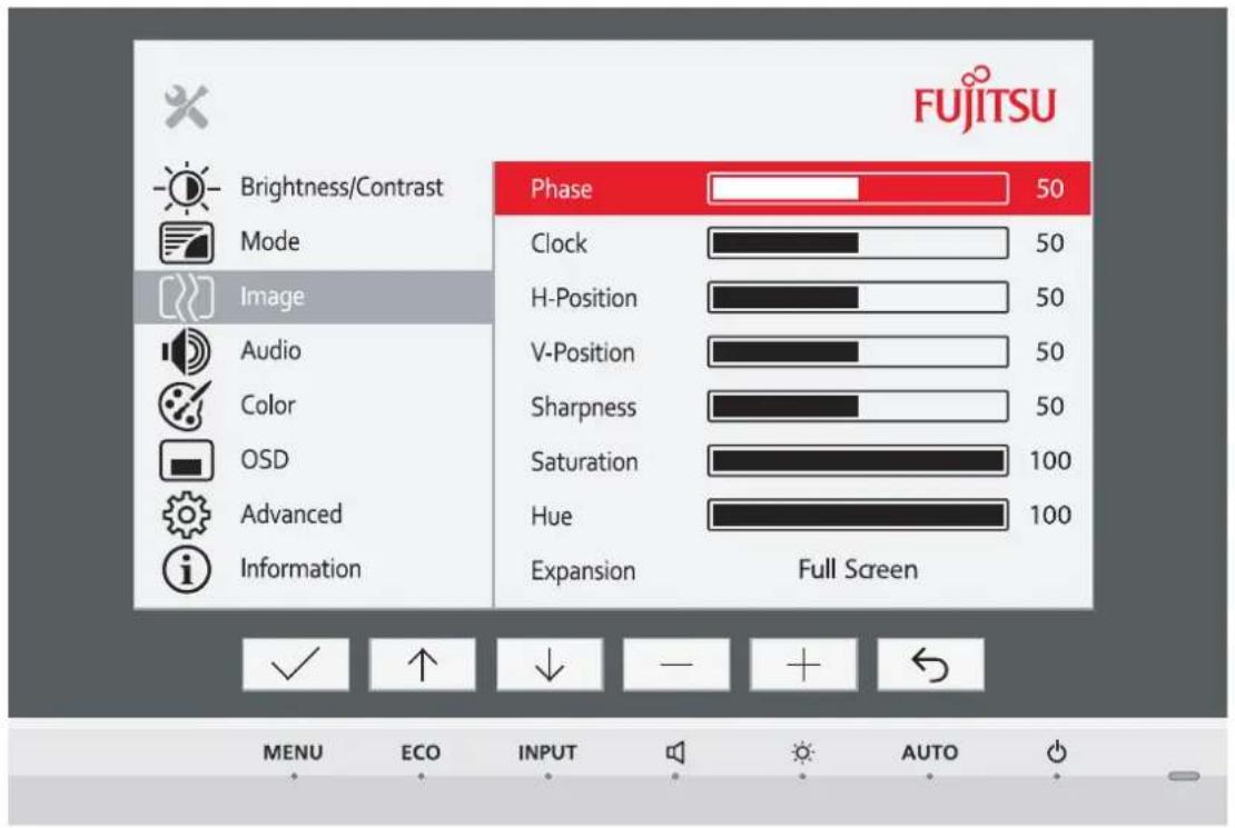
SUB D port
| Pin | Meaning |
| 1 | Video input red |
| 2 | Video input green |
| 3 | Video input blue |
| 4 | Ground |
| 5 | Ground |
| 6 | Video ground red |
| 7 | Video ground green |
| 8 | Video ground blue |
| 9 | +5 V (DDC) |
| 10 | Sync. ground |
| 11 | Ground |
| 12 | DDC Data |
| 13 | H. sync |
| 14 | V. sync |
| 15 | DDC Clock |
DVI-D port
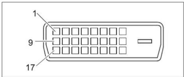
| Pin | Meaning |
| 1 | TMDS Data2- |
| 2 | TMDS Data2+ |
| 3 | TMDS Data 2/4 Shield |
| 4 | not connected |
| 5 | not connected |
| 6 | DDC Clock |
| 7 | DDC Data |
| 8 | Analog Vertical Sync |
| 9 | TMDS Data1- |
| 10 | TMDS Data1+ |
| 11 | TMDS Data 1/3 Shield |
| 12 | not connected |
| 13 | not connected |
| 14 | +5V Power |
| 15 | Earth |
| 16 | Hot Plug Detect |
| 17 | TMDS Data0- |
| 18 | TMDS Data0+ |
| 19 | TMDS Data 0/5 Shield |
| 20 | not connected |
| 21 | not connected |
| 22 | TMDS Clock Shield |
| 23 | TMDS Clock+ |
| 24 | TMDS Clock- |
DisplayPort socket
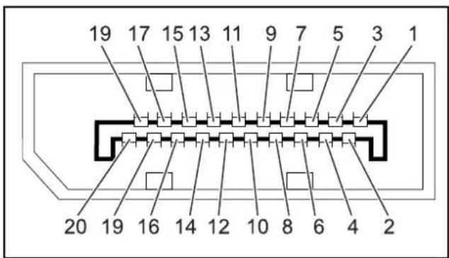
| Pin | Meaning |
| 1 | Lane 3 (negative) |
| 2 | Earth |
| 3 | Lane 3 (positive) |
| 4 | Lane 2 (negative) |
| 5 | Earth |
| 6 | Lane 2 (positive) |
| 7 | Lane 1 (negative) |
| 8 | Earth |
| 9 | Lane 1 (positive) |
| 10 | Lane 0 (negative) |
| 11 | Earth |
| 12 | Lane 0 (positive) |
| 13 | Connected to earth |
| 14 | Connected to earth |
| 15 | Auxiliary channel (positive) |
| 16 | Earth |
| 17 | Auxiliary channel (negative) |
| 18 | Hot Plug Detect |
| 19 | Return for Power |
| 20 | Power for connector(3.3 V 500 mA) |
HDMI port
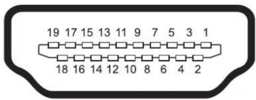
| Pin | Meaning |
| 1 | TMDS Data2+ |
| 2 | TMDS Data2 Shield |
| 3 | TMDS Data2- |
| 4 | TMDS Data1+ |
| 5 | TMDS Data1 Shield |
| 6 | TMDS Data1- |
| 7 | TMDS Data0+ |
| 8 | TMDS Data0 Shield |
| 9 | TMDS Data0- |
| 10 | TMDS Clock+ |
| 11 | TMDS Clock Shield |
| 12 | TMDS Clock- |
| 13 | CEC |
| 14 | N.C. |
| 15 | SCL |
| 16 | SDA |
| 17 | DDC/CEC Ground |
| 18 | +5 V Power |
| 19 | Hot plug detect |
- FUJITSU Display P24W-7 LED
- Congratulations on your purchase of an innovative product from Fujitsu.
- FUJITSU
- Operating Manual
- Remarks
- Trademarks
- Copyright
- Contents
- Your LCD screen.... 5
- Important notes 7
- Getting started 11
- Operation 22
- Notes on ergonomic colour adjustment 35
- Troubleshooting 36
- Explanatory information about standard ISO 9241-307 38
- Technical specification 39
- VESA-DDC-compatible VGA interface 40
- Your LCD screen...
- Target group
- Further information
- Important notes
- Safety instructions
- Power cable
- Transporting the device
- Cleaning the device
- CE marking
- Power management
- Disposal and recycling
- Getting started
- Unpacking and checking the delivery
- Setting up the device
- Setting up an ergonomic video workstation
- Mounting the monitor base
- Adjusting height
- Adjusting the inclination
- Adjusting the rotation
- Removing monitor base
- Connecting the device
- Connecting cables to the monitor
- Connecting cables to the computer
- MHL (Mobile High Definition Link)
- Using MHL
- Operation
- Switching the device on and off
- Using the touch sensors
- Notes on power management
- Notes on the ambient light sensor and presence sensor
- Changing the monitor settings
- Changing the monitor settings with the buttons of the control panel
- Select OSD language
- Activate/deactivate ECO operating mode
- Selecting the input signal
- Adjusting the volume
- Adjusting the brightness
- Performing auto-adjustment of the monitor
- Locking the OSD menu
- Locking the ON/OFF button or ON/OFF touch sensor
- Changing the monitor settings using the OSD menu
- OSD menu functions
- Adjusting the brightness and contrast
- Selecting the application mode
- Notes on ergonomic colour adjustment
- Troubleshooting
- Explanatory information about standard ISO 9241-307
- Permanently unlit or lit pixels
- Examples:
- Technical specification
- Environmental conditions
- VESA-DDC-compatible VGA interface
- Preset operating modes
- DVI-D port
- DisplayPort socket
- HDMI port
Marcă : FUJITSU
Model : P24W-7 LED
Categorie : Televizor