PG-2W - Caméra de surveillance vidéo Joblotron - Manual de utilizare gratuit
Găsiți gratuit manualul dispozitivului PG-2W Joblotron în format PDF.

Întrebările utilizatorilor despre PG-2W Joblotron
0 întrebare despre acest aparat. Răspundeți la cele pe care le cunoașteți sau puneți-vă propria.
Pune o întrebare nouă despre acest aparat
Descărcați instrucțiunile pentru Caméra de surveillance vidéo în format PDF gratuit! Găsiți manualul dvs. PG-2W - Joblotron și luați din nou în mână dispozitivul dvs. electronic. Pe această pagină sunt publicate toate documentele necesare pentru utilizarea dispozitivului dvs. PG-2W mărcii Joblotron.
MANUAL DE UTILIZARE PG-2W Joblotron
ALARM PAGER SET PG-2W
ver. 1.1.e
The PG-2W pager is designed for the wireless transmission =of =a =car =alarm =signal =and =for =local paging. =Additionally, this device =can =be =used for remote =indication =of ==other =signals. =The =working distance =of =this =system =is =2 =km =(open =area, transmitter =antenna =installed =properly). =The =PG-2W set includes: transmitter PG-2T, receiver PG-2R, =tape =antenna =PG-2A, =keypad =for =manual triggering and wire-harness.
The transmitter =can=send=three=different signals =(it=has=three=signal=inputs=-=zones). Additional =signals=can==be=sent=if=the=keypad=for manual triggering is connected to the transmitter. Each transmitter has a unique transmitting digital code =(factory=set). =This=code=insures=that=only=a receiver=which=was=set=(taught)=for=this=code=will react=to=the=transmitted=signal.=An=unlimited number=of=receivers can=be=set(taught) for=each transmitter.
The =transmission =of =the =signal =can =be =carried through =the =adhesive =tape =antenna =or =it =can =be sent =through =the =car =radio =antenna. =If =an automatic =antenna =is =installed, =the =pager =can provide a signal to extend the antenna.
The pocket size receiver can be carried = or clipped = on = your = belt. It responds with = an = audi and = visual = signal = if = the = corresponding = code = is received. Each receiver can recognize up to three distinct transmitters. So, one receiver is capable of = monitoring = up = to = three = cars. = You = can distinguish = which transmitter (car) = is = signaling = by the color of the CAR LED (red, green or orange). The = color = of = the = ZONE = LED = distinguishes = which input = of the = transmitter = was = triggered = or which button on the keypad was pressed. The receiver reacts differently = for = alarms = and = for = = manual paging. All information received is stored into the receiver's = ALARM memory =(six = levels). = The = user can easily check the memory. The PG-2R receiver is = powered = by = two = AAA = size batteries. The condition of the batteries are checked automatically.
Specifications:
transmitter:
| operating voltage | 10 - 15VDC |
| consumption | stand by10mA, act. 0.7A |
| frequency | 27 MHz band |
| radiated power | max. 4W |
| working distance | up to 2km (open area) |
| code | digital (1.000.000 codes) |
| transmitting max. | 30sec after triggering |
receiver:
| power | 2x battery 1.5V, size AAA |
| consumption | 1.2mA |
| indication | audible & visual |
| antenna | built in frame antenna |
| dimensions | 75 x 55 x 17mm |
Installation:
The =transmitter =should =be =installed =in =the passenger =compartment =of =the =car. =Avoid locating =it =close =to =any =other =electronic =devic Use =two screws =or =double =sided =adhesive =tap to attach the transmitter unit.
Antenna - =the adhesive =tape =antenna =PG-2A should be fixed to a window. It should be located at =least =10mm = away =from =the =edge =of =the window. =Do =not =install =the =antenna =on =a =wind with =a =built =in =defroster. =Use =the =screened =c (provided in =the kit) to =connect the antenna. This cable has a connector on one end and two leads (core and =screen) on the =other end. =Connect the cable core lead to the tape antenna. This connection should be as short as possible (cut the =wire =to =the =desired =length). =Insulate =this connection =properly =with =electrical =tape. =Then connect the screen lead with the car body (GND).
This = connection = should = again = be = as = short = as possible. = The = car = body = works = as = the = second antenna pole. Plug the connector on the other end of the cable into the ANTENNA connector on
the PG-2T transmitter. The length of the cable can not be increased, so be sure to predetermine the =location of =the =transmitter =in =reference =to antenna cable.
You can =also=use car radio antenna for the pager. =However, =only an =antenna =which =is =ne equipped with a built in preamplifier can be used. Additionally, =the =active part of the =antenna must be longer than 1.2m. To use the car antenna, connect the antenna cable directly into the ANTENNA =connector =on =the =PG-2T =transmitter. Then, use the connecting cable (equipped with connectors =on =both =ends -= provided in =the =k connect =the =RADIO =connector =on =the =pager the =antenna =input =on =the =car =radio. =The =PG transmitter =has =a =built-in =signal =splitter =which allows the signal from antenna to reach the radio and =will =not =interfere =with =the =radio =reception. When the pager is triggered, the antenna is used for the pager transmission.
If =an =automatic =antenna =is =installed, =the =pa also provides a signal to extend the antenna (gray wire).
Note: some car radio antennas do not transmit the band of 27 MHz well. If this is the case with your antenna, you will realize this when you write the pager's working distance. The ideal antenna for the pager is a CB car antenna.
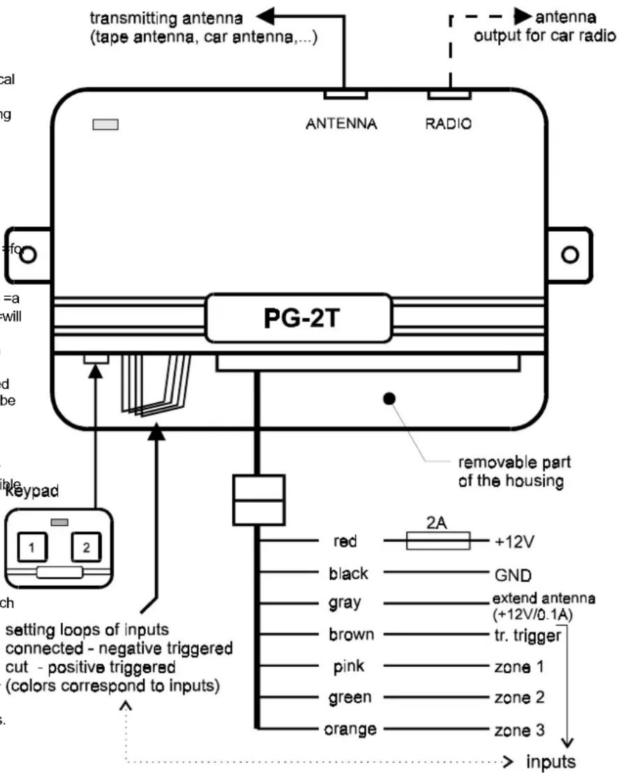
Wiring:
The wire-harness is equipped with a connector which makes the installation easier. If you do not use some wires in the =harness, you can release the wires from the connector (pressing =the=connector=tab=inside=the=hous with=a narrow=screwdriver).=The transmitter housing has a removable part on the side of the wire outputs. Place the ends =of your=fingers=on the =wire =output =slot =and =pull =the =upper =part =of the =housing =up =to =open =the =output =section. =theide, =you =will =find =the =keypad =connector =and four =colored =wire =loops. =These =loops =can =be used =to =change =the =triggering =polarity =of =the corresponding colored input wires.
Keypad =for =manual =operation =- =install =this keypad =in =a =suitable =place =inside =the =car =(use the adhesive tape that is attached to the keypad). Plug the keypad cable into the connector on the transmitter unit. Note: The keypad is optional and the pager will work with the keypad uninstalled.
Wires:
Black == =GND =Supply. =Connect =this =wire =to =the original GND point in the car.
Red = Positive Supply (the wire with a 2A fuse). It = should = be = connected = directly = to = the = positive terminal of the battery cable (usually marked as signal number 30 on the car wireharness). Gray = output for automatic antenna actuator control. = There = is = a = +12V/max.100mA = when = the pager = transmitter = is = active. = Remove = this = wire = if you do not use an automatic antenna.
Note: the following four wires are inputs. They all are negative triggered (an input is active when connected with the GND). If you need any of them as a positive triggered input (active when connected with +12V), cut the wire setting (programming) loop with corresponding color. The setting links are located in the output section of the transmitter. Do not forget to insulate ends of the wires with electrical tape if you cut any link.
Brown = transmitting trigger. = If this input is active = (for = at least = 5 seconds =), = the transmitter will send information regarding which zone input
is =(or =was) =triggered. =So =there =are =two conditions =for =a =transmission: =a =zone =input triggering =and =an =activation =of =the =transmitting trigger. If the transmission trigger input is active for =a =longer =period, =the =transmission =will automatically be terminated after 30 seconds. Pink, green, orange = zone inputs. These inputs determine =which =color =of =the =ZONE =LED =on =receiver will light when the alarm is triggered. One of these inputs must be triggered (it can be only a short =pulse) =at =the =same =time =(or =before) =the transmission =trigger =(brown =wire) =is =activated. Signals in these inputs are valid only if =they were finished within one second before the transmitting trigger. If they are generated during the transmitting trigger they will also be valid.
More inputs can be triggered simultaneously (or gradually) = during = one = transmission = period. = The ZONE LED on the receiver will repeatedly alternate between the corresponding colors.
The ZONE LED has the =following colors (red = pink input, green == green input, orange == orange input).
Examples of use:
Installation in a car equipped with a car alarm (following description is valid for CA-300 Jablotron =car =alarm). =Cut =the =brown =and pink setting =loops =in =the =PG-2T =transmitter =at =first. Connect =the brown and =pink =wires parallel =to =the siren =output =of the car =alarm. Connect =the =green wire =parallel =to =the =output =of =ultrasonic =detect and the orange wire parallel to the door switches. When installed in this way, each alarm will be indicated =with =red =flashes =of =the =ZONE =LED : the pager receiver. If an alarm is triggered by the ultrasonic =detector, =then =the =ZONE =LED =will alternate red flashes with green flashes. When the =LED =alternates =between =red =flashes =and orange flashes, it means that the alarm was triggered =by =a =door =switch. =If =the =ZONE =LED alternates =between =all =three colors, =the =door switch =and =the =ultrasonic =detector =were =booth triggered.
Installation in a car without a car alarm (for example in a car equipped with an immobilizer). The easiest solution in this case is that you will only connect =the brown and pink =wires with the door =switches. =The =other =wires =will =not =be connected =(remove =them =from =the connector) In this case, your receiver will inform you when anybody opens a door.
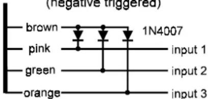
If = there = are = more = sensors = available = in = the (hood and trunk switches etc.), you can get three independent inputs on the pager transmitter. Use diodes connected as shown on the diagram.
how to get three independent inputs (negative triggered)
Installation with a house alarm system. When a telephone line is not available to transfer an alarm signal, you =can use the =PG-2W =for this purpose. =You =again =can=choose=if=you=will=only one alarm signal (parallel connection of pink and =brown=wires=with=siren=output only),=or=distinguish three different signals (see the description above).
You can also use the adhesive tape antenna on a =house =window =for =the =transmitter. =Connect =screen =lead =of =the =antenna =cable =to =the =ear this case.
A better solution for the use in a house is to use an =additional =antenna =with =the =receiver. =See section "How to =increase working =distance =". =We also =recommend =an =external =power =supply module (model =PG-2M) =for =the =receiver. =This module = provides = an = alarm = signal = on = a = dry contact output as well.
Preparation of the receiver - Insert two AAA size batteries to the PG-2R receiver. The receiver provided =in =the =kit =has =been =preset =for =the provided =transmitter's =code =by =the =manufacture (the receiver's CAR LED will be red for this transmitter). =If =you =add =a =new =receiver(s) =to transmitter, =you =must =teach =it =the =transmitter communication =code. =Each =PG-2T =transmitter has a unique code. Each PG-2R receiver can be taught a maximum of three transmitter codes.
Setting code procedure:
Note that =the =sliding =switch =for =turning =the receiver =on =and =off =can =also =be =pushed =in button switch. With the switch in the OFF position, =press =the =switch =in =and =hold =it =wh sliding it to the ON position. Hold the button pressed =until =the =receiver beeps. =When =you release the button, the ZONE LED will light orange permanently and CAR =LED will flash red. This is confirmation that you have entered the learning mode.
You =can=change=the=color=of=the=CAR=LE quickly pressing the button. Each press of the button will=change=the=color.=Use=this=method set the color you want the receiver to show when it=receives=a=signal=from=the=transmitter.=After selecting the desired color, trigger the transmitter (with keypad or with an alarm input). The receiver will=confirm=with=five=short=beeps=that=the=was stored to the memory (approximately 10 sec. after the transmitter triggering).=The=receiver=will now be in stand by mode, indicated by booth LEDs tuning off. You can also terminate the learning mode at any point by sliding the switch to the off position.
If you want to teach the receiver an additional transmitter code, enter the learning mode again, set requested color of the CAR LED and trigger the next transmitter.
When your receiver =has already =learned codes for other transmitters and you want to reset it for only =one =transmitter, =teach =the =transmitter =code into all three colors of the CAR LED. The receiver will recognize that all the codes are the same and the =green =and =orange =code =memory =will =be erased. =Now =the =receiver =will =react =only =to transmitter (with red color of the CAR LED).
Note: If you leave the receiver in the learning mode without any input, it will automatically return to the stand by mode after 4 minutes (v any change of the settings). All the codes are stored in non voltage memory, so the receiver will remember them even if the batteries are disconnected.
OPERATION
Stand by mode - slide the switch on the receiver to the ON position. The receiver will confirm =that =it =is =ready =with =a =short =beep flash of both LEDs.
When alarm signal received ==the=receive reacts with audible and visual signals. If you hear 9 beeps repeatedly and the ZONE and the CAR LEDs are flashing, it means that a zone input has been triggered (see color of the ZONE LED). You can=stop=the signals=(confirm=reception)=by=sh pressing the=switch=button=down.=This=stores=sinformation to the memory. If the button is not pressed within 30 seconds, the information will be automatically stored to the memory.
When manual paging signal received - you can hear 3 beeps repeatedly and the ZONE and the CAR LED will flash. It means that somebody pressed a button on the transmitter keypad. You can = recognize = which = button = was = pressed according to = the = ZONE = LED = color = (orange = button no.1, green = button no.2, red = both buttons simultaneously). You can stop the signals (confirm reception) by short pressing the switch = button down. = This = stores = the information to =the =memory. =If =the =button =is =not =pressed within 30 seconds, the information will be automatically stored to the memory.
Indication of new information stored in the memory - if a signal was automatically stored (was not confirmed by user), the receiver will beep = once = every 60 = seconds. = Pushing = the sketch button once will acknowledge the new information and the beeping will stop.
| CAR(transmitter) | ZONE | ||
| red | green | orange | |
| red | |||
| green | |||
| as = aorange | |||
Memory information reading = - = press = and = hold the switch button on the receiver to check the most = recent = event = in = the = memory. = You = will = see which car (transmitter) signaled on the CAR LED and what happened on the ZONE LED. If the information = was = sent = manually = from = the = keypad, both = LEDs = will = flash = simultaneously = and = the Receiver will be silent. If it was an alarm signal, the LEDs will flash and the receiver will also beep. If the ZONE LED alternates = its = color, = it = means that multiple = zones = on = the = transmitter = were triggered. The = receiver = has = 6 events = memory. = By = pressing and holding the button you can see the latest event. If you release the button for a moment code (max. 1 second) = and = press it again, = you = can see the second most recent event. The same method can = be = used = to = view = the = remaining = events = in order. If you hear 3 beeps after pressing the button, it means that there is no more information in the memory (the LEDs will remain off). If = you release = the = button = for = more = than = 3 = seconds = and then press it again, the memory will return to the most recent event.
Memory reset = - = switch = off = the = receiver = and = all events information will be erased.
Battery check - receiver performs an automatic battery =condition =check =when =it =is =in =the =stand by =mode. =If =the =batteries =are =low, = the =receiver will beep twice every five minutes.
How to increase the working distance
The working =distance is =essentially =determined by =the =quality =of =the =transmitter =antenna. =If =you desire a longer working distance for the pager installed in your car, we recommend the use of a CB =car =antenna. =Such =an =antenna =should =be installed and adjusted by a CB radio professional.
If =you =use =the =pager =for =a =house =alarm =(fixed installation of the transmitter), you can use an additional wire =antenna, =model ANT-1. =This antenna =has =a =5m =span =and =can =be =installed vertically =or =horizontally =(for example =on the house roof). Install the transmitter unit close to the antenna =(do not =make =the antenna =cable longer).
If you install the receiver in a permanent location, =we =also =recommend =an =additional antenna. You can use a wire (5m as a minimum). Locate the wire in a location that is not screened by =any =large =metal =objects. =Lead =one =end =of the wire =to =the =receiver. =Make =four =turns =of =the =wire around the receiver housing and connect the end of the wire to the ground (central heating, protective earth etc.). In this way, the receiver will receive =the =signal =via =inductive ==coupling. =If =you install an additional antenna to the transmitter and the receiver =as =well, =you =will =have =a =significantly further working distance.
For fixed installation of the receiver we recommend an external power supply module (model PG-2M). This module provides alarm signal on a dry contact output as well.