LWH1737 511 - Suport de perete Schwaiger - Manual de utilizare gratuit
Găsiți gratuit manualul dispozitivului LWH1737 511 Schwaiger în format PDF.

Întrebările utilizatorilor despre LWH1737 511 Schwaiger
0 întrebare despre acest aparat. Răspundeți la cele pe care le cunoașteți sau puneți-vă propria.
Pune o întrebare nouă despre acest aparat
Descărcați instrucțiunile pentru Suport de perete în format PDF gratuit! Găsiți manualul dvs. LWH1737 511 - Schwaiger și luați din nou în mână dispozitivul dvs. electronic. Pe această pagină sunt publicate toate documentele necesare pentru utilizarea dispozitivului dvs. LWH1737 511 mărcii Schwaiger.
MANUAL DE UTILIZARE LWH1737 511 Schwaiger
MONTAGEANLEITUNG
INSTRUCTION MANUAL
D
GB
natural_image
3D rendered object resembling a smartphone with a keyhole symbol (no text or labels)

natural_image
Black 3D object resembling a stylized letter 'E' or bracket with cutouts, no visible text or symbols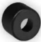
D
HERSTELLERINFORMATION
Sehr geehrter Kunde,
sollten Sie technischen Rat benötigen und Ihr Fachhändler konnte Ihnen nicht weiterhelfen kontaktieren Sie bitte unseren technischen Support.
Schwaiger GmbH
Würzburger Straße 17
90579 Langenzenn
Hotline: +49 (0) 9101 702-299
www.schwaiger.de
info@schwaiger.de
Geschäftszeiten:
Montag bis Donnerstag: 08:00 - 17:00 Uhr
Freitag: 08:00 - 14:30 Uhr
Inhaltsverzeichnis
WARNUNG 4
Sicherheitshinweise....4
Benötigtes Werkzeug 4
Paketinhalt. 5
Montage an der Steinwand 6
Installieren der Montage- und Abstandshalter 8
An der Rückseite von Flachbildschirmen 8
Einhängen des TV-Geräts in die Halterung....10
Wartung....10
Technische Daten 11
D
D
WARNUNG
- Beginnen Sie mit der Installation des Produkts erst, nachdem Sie die Anweisungen und Warnungen in dieser Installationsanleitung gelesen und verstanden haben. Falls Sie irgendwelche Fragen zu einer Anweisung oder Warnung haben, nehmen Sie bitte Kontakt mit Ihrem Händler vor Ort auf.
- Bitte beachten Sie bezüglich des erforderlichen Abstands von der Wand die Empfehlung in der Installationsanleitung, um das Risiko von Sachschäden zu vermeiden.
- Dieses Produkt sollte nur von einer Person mit guten mechanischen Fähigkeiten und grundlegenden Erfahrungen im Hinblick auf Gebäudekonstruktion installiert werden.
- Stellen Sie sicher, dass die Stützfläche das kombinierte Gewicht aller Geräte, angebrachter Hardware und Komponenten sicher trägt.
- Überschreiten Sie niemals die maximale Tragfähigkeit.
- Stellen Sie bei Montage in Wandpfosten aus Holz sicher, dass die Befestigungsschrauben in der Mitte der Pfosten verankert sind. Die Verwendung eines Auf-Stoß-Balkensuchers wird dringend empfohlen.
- Setzen Sie immer einen Helfer oder eine mechanische Hebevorrichtung ein, um Geräte sicher anzuheben und zu positionieren.
- Ziehen Sie Schrauben fest an, ohne diese jedoch zu überdrehen. Ein Überdrehen kann die Komponenten beschädigen, wodurch deren Haltekraft erheblich reduziert wird.
- Dieses Produkt ist nur zur Verwendung in Innenräumen vorgesehen. Eine Verwendung des Produkts im Freien könnte zu Produktversagen und Personenschäden führen.
Sicherheitshinweise
Wenn Sie Zweifel an einer sicheren Montage haben, lassen Sie diese von einem qualifizierten Fachmann ausführen.
SCHWAIGER kann nicht für Schäden oder Verletzungen verantwortlich gemacht werden, die durch falsche Montage oder nicht bestimmungsgemäßen Gebrauch verursacht wurden.
Beachte: Das mitgelieferte Befestigungsmaterial ist nur für massive Wandkonstruktionen geeignet. Wenn Sie sich nicht über die Beschaffenheit der vorhandenen Wand im Klaren sind, konsultieren Sie einen Fachmann. Das mitgelieferte Zubehör ist nicht für Stahl geeignet.
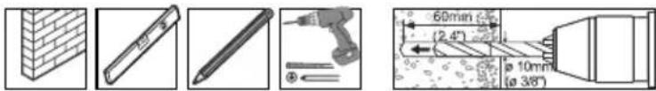
Benötigtes Werkzeug
Kreuzschlitzschraubendreher
Bohrmaschine und 10 mm Mauerbohrer
Markierungsstift
Hammer
Wichtig:
Beginnen Sie mit der Installation des Produkts erst, nachdem Sie die Anweisungen und Warnungen in dieser Installationsanleitung gelesen und verstanden haben. Falls Sie irgendwelche Fragen zu einer Anweisung oder Warnung haben, nehmen Sie bitte Kontakt mit Ihrem Händler vor Ort auf.
natural_image
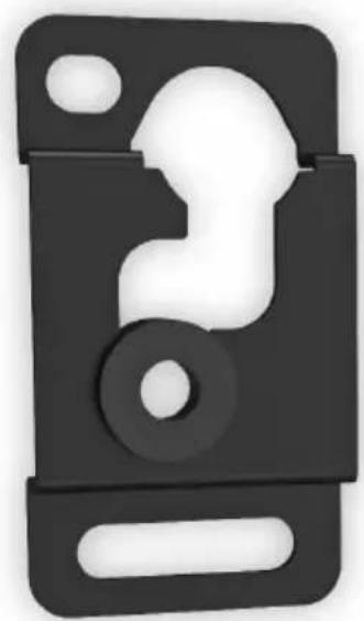
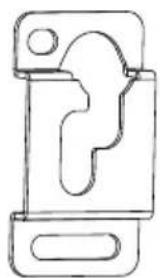
Simple line drawing of a mechanical clamp or bracket (no text or symbols)Wandhalterung (2x) A
Adapterhalterung (2x)
B
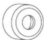
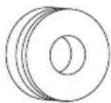
Abstandshalter (2x)
C
Montagezubehör
M4x14 (x2)
M-A
M4x20 (x2)
M-B
M5x14 (x2)
M-C
M5x20 (x2)
M-D
M6x14 (x2)
M-E
M6x20 (x2)
M-F
M8x20 (x2)
M-G
M8x25 (x2)
M-H

D5 (x4)
M-1

D8 (x4)
M-J

M-K (x8)
M-L (x4)
M-M (x4)

M-N (x4)
D
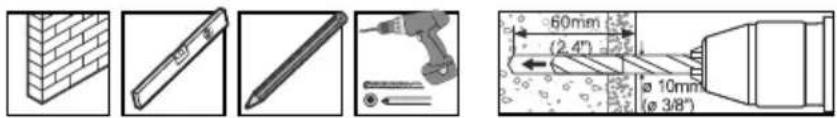
1.1 Montage an der Steinwand
text_image
Technical diagram showing five different tool and component arrangements with dimensions and angles labeledLöcher vorbohren.
natural_image
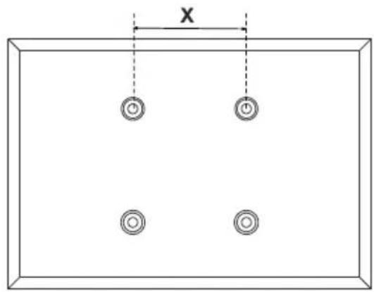
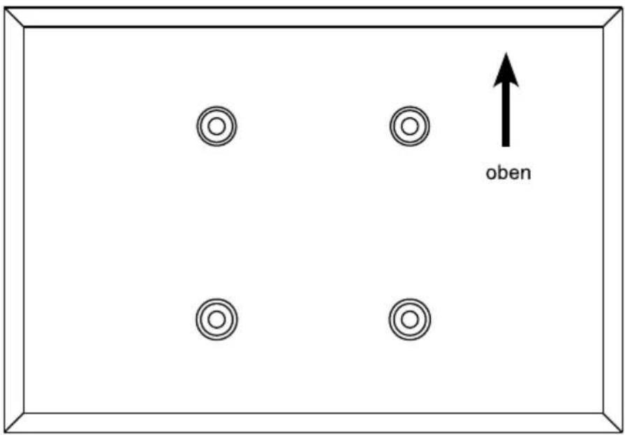
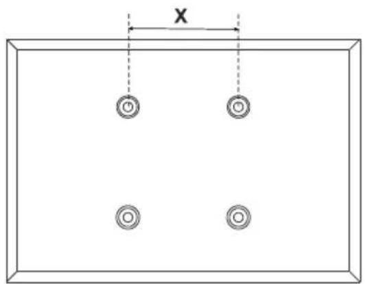
Simple diagram of a rectangle with four circular holes and a horizontal dimension labeled 'X' (no text or symbols beyond basic geometry)Schrauben Sie die Wandhalterung an.
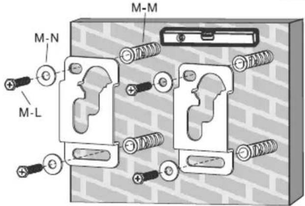
text_image
M-N M-L M-M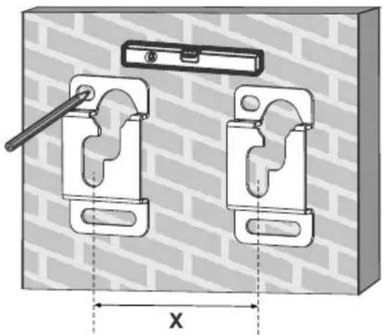
natural_image
Technical diagram of two mechanical clamps mounted on a brick wall, with dimension X shown (no text or symbols)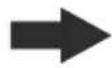
natural_image
Technical illustration of two mechanical clamp components mounted on a brick wall, with no visible text or symbols.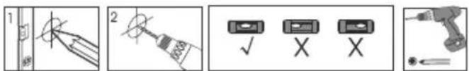
text_image
Technical diagram showing five different tool or component configurations with labeled parts and symbolsAchtung:
Der Abstand der Wandhalter richtet sich nach dem horizontalen VESA-Abstand Ihres TV-Gerätes.
WARNUNG
D
- Stellen Sie bei der Montage der Wandhalterung an Porenbetonstein sicher, dass für die Dübel in dem Loch mindestens 1-3/8" tatsächliche Betonstärke vorhanden sind. Bohren Sie nicht in Mörtelfugen! Stellen Sie sicher, in einen soliden Teil des Steins zu bohren, im Allgemeinen mindestens 2,5 cm von der Seite des Steins entfernt. Anstelle einer Schlagbohrmaschine wird zum Bohren des Lochs eine Bohrmaschine mit langsamen Lauf empfohlen, um zu verhindern, dass das Loch hinten ausbricht, wenn Sie auf ein Loch oder einen Hohlraum treffen.
- Der Installateur muss sicherstellen, dass die Stützfläche das kombinierte Gewicht aller Geräte, angebrachter Hardware und Komponenten sicher trägt.
- Bohren Sie diese Löcher mit einem 10 mm Mauerbohrer mindestens 60 mm tief vor. Stecken Sie in jedes Loch einen Dübel (M-M). Drehen Sie die Schlüsselschrauben (M-L) in die Wand ein, ohne diese zu überdrehen.
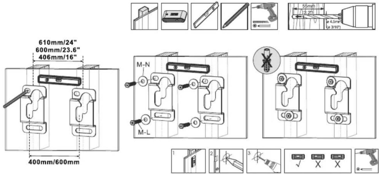
1.2 Montage an der Holzwand
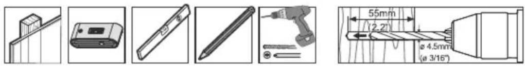
text_image
Technical diagram showing various mechanical components and dimensions, including a slide, pencil, screwdriver, and cutting tool.
text_image
610mm/24" 600mm/23.6" 406mm/16" 400mm/600mm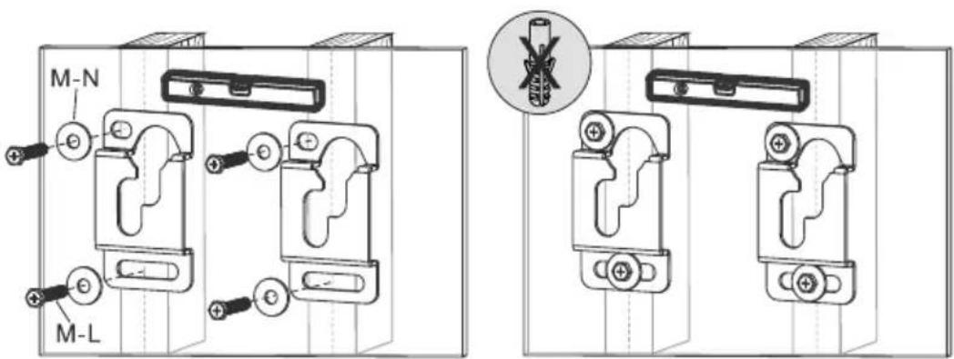
text_image
M-N M-L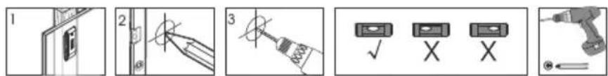
text_image
Diagram showing five-step electrical circuit or tool installation steps with labeled icons and symbolsD
2. Installieren der Montage- und Abstandshalter
text_image
oben2.1 An der Rückseite von Flachbildschirmen
text_image
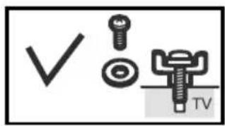
✓ TV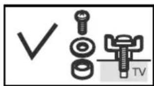
text_image
✓ TV
text_image
× TV TV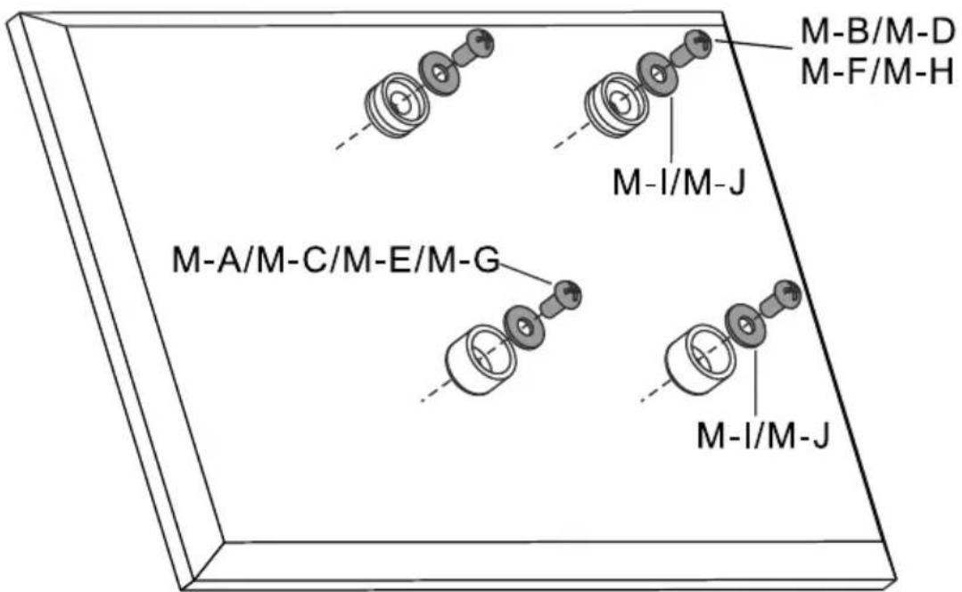
text_image
M-A/M-C/M-E/M-G M-I/M-J M-I/M-J M-B/M-D M-F/M-H
natural_image
Technical line drawing of a mechanical assembly with multiple circular components and shafts, no text or symbols present.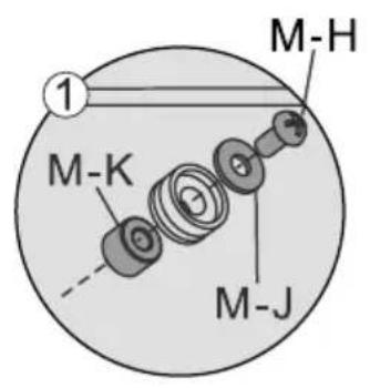
text_image
M-H 1 M-K M-J
text_image
M-H ② M-K M-J
text_image
M-J M-G M-K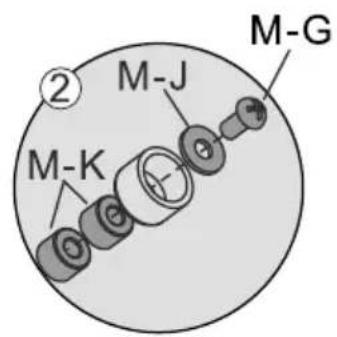
text_image
M-K M-J M-G3. Einhängen des TV-Geräts in die Halterung
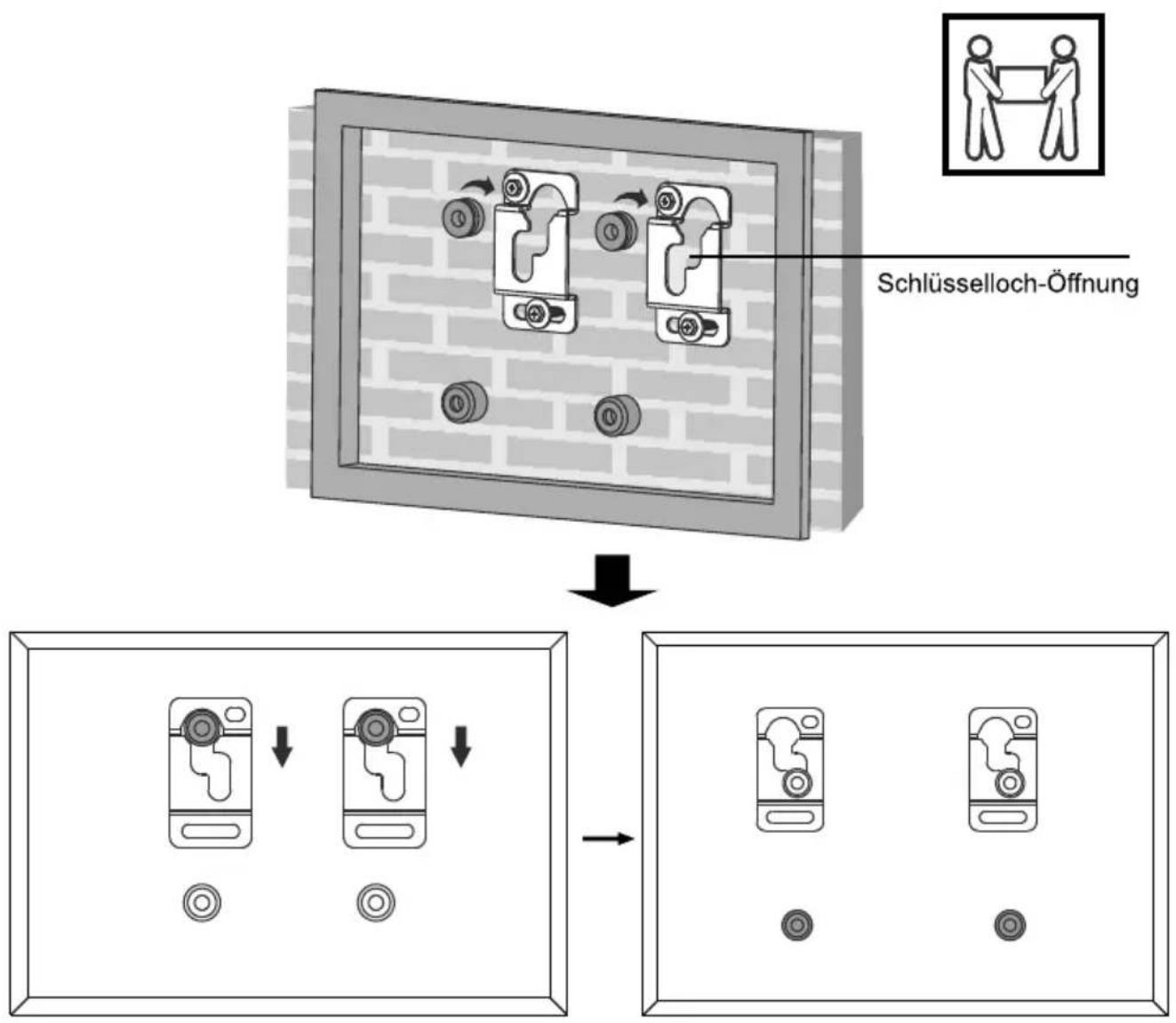
flowchart
graph TD
    A["Schlüsselloch-Öffnung"] --> B["Device Placement"]
    B --> C["Adjustment to Screen"]
    C --> D["Final Display"]
    style A fill:#f9f,stroke:#333
    style B fill:#ccf,stroke:#333
    style C fill:#cfc,stroke:#333
    style D fill:#fcc,stroke:#333
Wartung
Sobald Sie die Halterung und den Flachbildschirm montiert haben, überprüfen Sie, dass diese ausreichend gesichert und sicher zu nutzen sind. Sie sollten den festen Sitz aller Schrauben alle zwei Monate kontrollieren. Falls Sie wegen der Installation Bedenken haben, nehmen Sie wegen Details bitte mit Ihrem Händler oder der Serviceabteilung Kontakt auf.
text_image
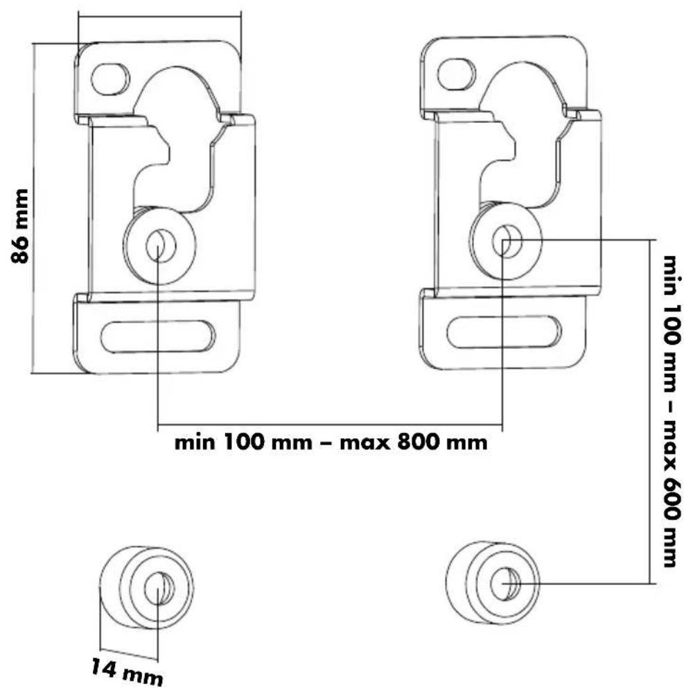
86 mm min 100 mm - max 800 mm 14 mm min 100 mm - max 600 mm
text_image
fix 14mm
text_image
50 kg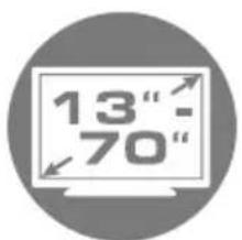
text_image
13" - 70"
text_image
max. 178 cm
text_image
VESA max. 800
COMPANY INFORMATION
GB
Dear customer,
In case you will need further technical support and your dealer is not available please contact our help line:
Schwaiger GmbH
Würzburger Straße 17
90579 Langenzenn
Hotline: +49 (0) 9101 702-299
www.schwaiger.de
info@schwaiger.de
Opening hours
Monday to Thursday: 08:00-17:00 h
Friday: 08:00-14:30 h
Contents
WARNING 14
Safety Notes 14
Tools 14
Package content 15
For Solid Brick and Concrete Mounting.... 16
Install Adapter Brackets. 17
For Flat Back Screen.... 17
Hanging the TV onto the Wall Plate.... 19
Maintenance 19
Technical Information....20
WARNING
- Do not begin the installation until you have read and understood the instructions and warnings contained in this installation sheet. If you have any question regarding any of the instructions or warnings, please contact your local distributor.
- This mounting bracket was designed to be installed and utilised ONLY as specified in this manual. Improper installation of this product may cause damage or serious injury.
- This product should only be installed by someone with good mechanical ability who has basic building experience and fully understands this manual.
- Make sure that the supporting surface will safely support the combined weight of the equipment and all attached hardware and components.
• Always use an assistant or mechanical lifting equipment to safely lift and position the equipment. - Tighten screws firmly, but do not over tighten. Over tightening can cause damage to the items, This greatly reduces their holding power.
- This product is intended for indoor use only. Using this product outdoors could lead to product failure and personal injury.
Safety Notes
If you have doubts about a safe installation, have it installed by a qualified technician.
SCHWAIGER can not be held responsible for damage or injury caused by improper installation or improper use.
Note: The included mounting hardware is only suitable for solid wall/ceiling construction. If you are not sure of the condition of the existing wall/ceiling in mind, consult a specialist. The included hardware is not suitable for steel.
Tools
Cross screwdriver
Power drill and 10 mm drill bits for stone
Pencil
Mallet
IMPORTANT:
Ensure that you have received all parts according to the component checklist prior to installation. If any parts are missing or faulty, telephone your local distributor for a replacement.
GB
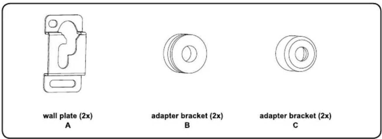
text_image
wall plate (2x) A adapter bracket (2x) B adapter bracket (2x) CMounting accessories
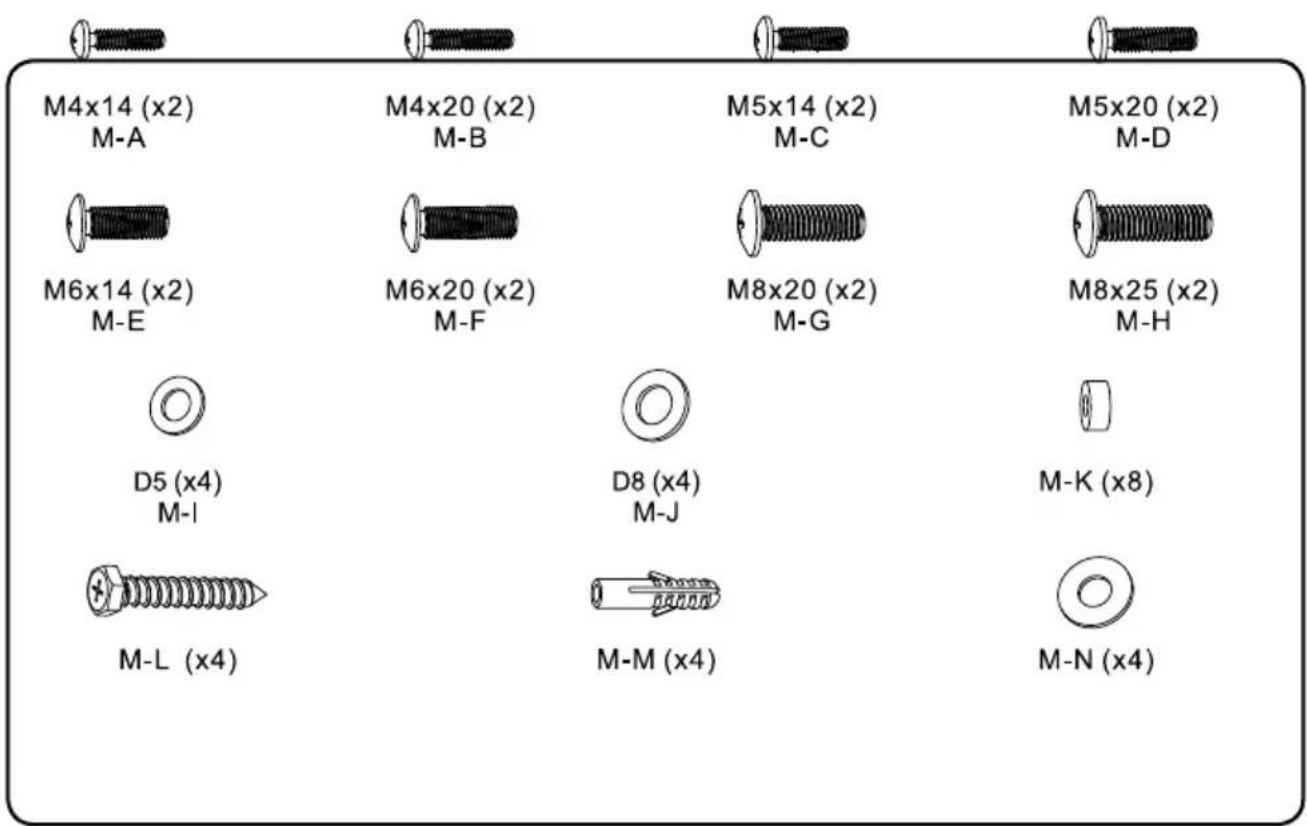
text_image
M4x14 (x2) M-A M4x20 (x2) M-B M5x14 (x2) M-C M5x20 (x2) M-D M6x14 (x2) M-E M6x20 (x2) M-F M8x20 (x2) M-G M8x25 (x2) M-H D5 (x4) M-I D8 (x4) M-J M-K (x8) M-L (x4) M-M (x4) M-N (x4)1.1 For Solid Brick and Concrete Mounting
WARNING
- When installing wall mounts on cinder block, verify the actual concrete thickness is at least 1-3/8" (35mm) for using the concrete anchors. Do not drill into mortar joints! Be sure to mount in a solid part of the block, generally 1" (25mm) minimum from the side of the block. It is suggested electric drill on slow setting is used to drill the hole instead of a hammer drill to avoid breaking out the back of the hole when entering a void or cavity.
• Installers must verify that the supporting surface will safely support the combined load of the equipment and all attached hardware and components.
Drill pilot holes.
text_image
Technical diagram showing five different tool states: brick wall, pencil, screwdriver, drill bit, and drill bit with dimensional annotations.Screw wall plates onto the wall.
GB
natural_image
Simple diagram showing three circular elements suspended vertically within a rectangle, with an X-axis label (no text or symbols beyond the label)
text_image
M-N M-L M-M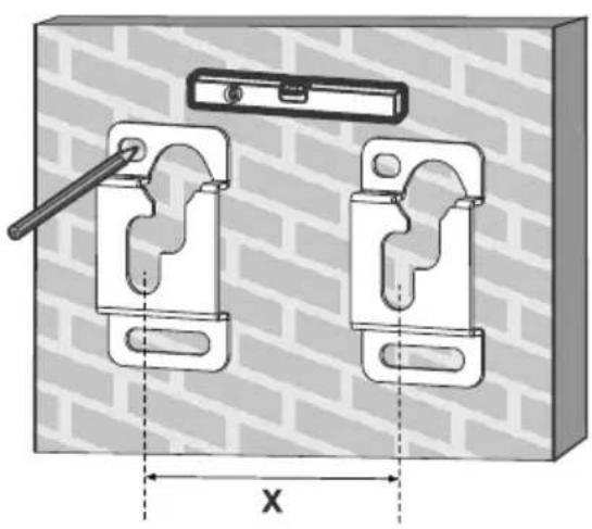
natural_image
Technical diagram of a mechanical clamp device with two mounting brackets and a handle, set against a brick wall background (no text or symbols)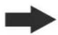
natural_image
Technical illustration of two mechanical clamp components mounted on a brick wall, with no visible text or symbols.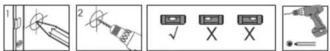
text_image
Technical diagram showing tool application steps: pinning, tool tip, inspection, and disassembly with check, X, and X icons.1.2 Montage an der Holzwand
text_image
610mm/24" 600mm/23.6" 406mm/16" 400mm/600mm M-N M-L 55mm (12.20) a 4.5mm (a 3/16)2. Install Adapter Brackets
GB
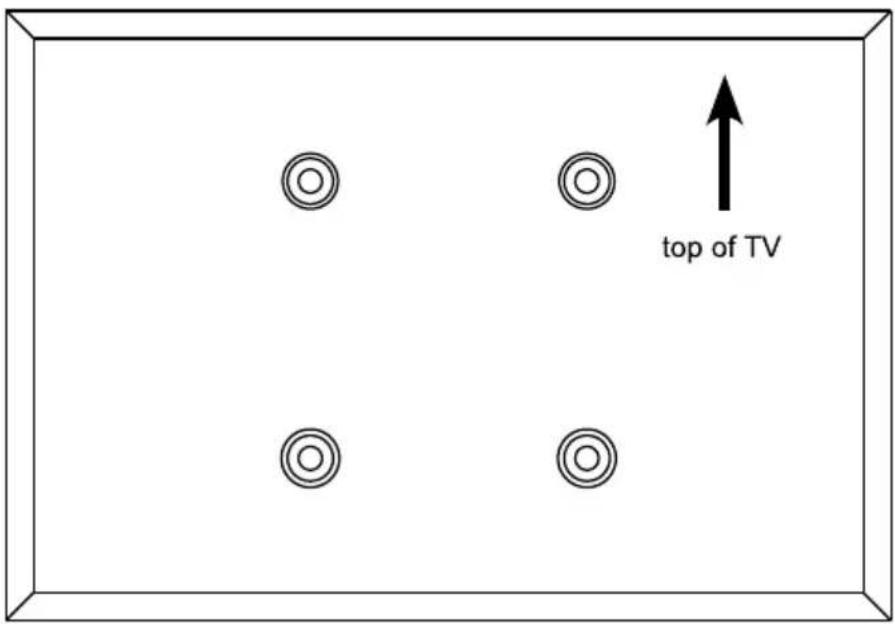
text_image
top of TV2.1 For Flat Back Screen

text_image
✓ TV
text_image
✓ TV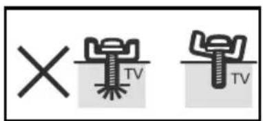
text_image
× TV TV
text_image
M-A/M-C/M-E/M-G M-I/M-J M-I/M-J M-B/M-D M-F/M-H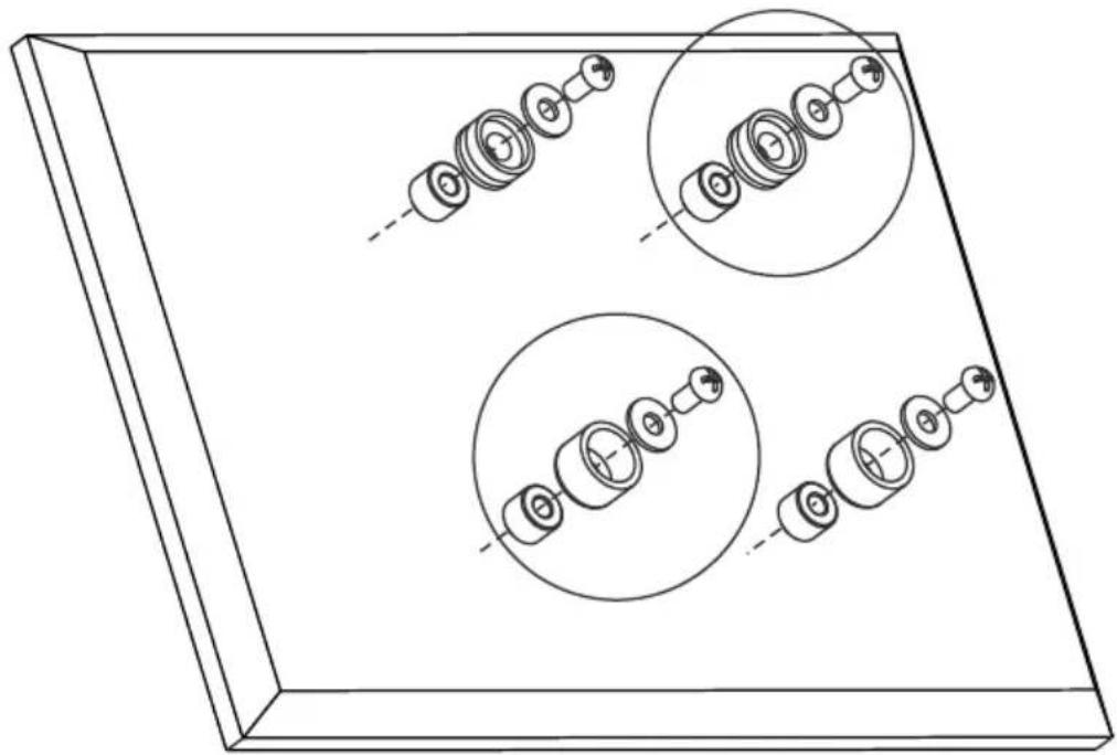
natural_image
Technical line drawing of a mechanical assembly with multiple circular components and dashed alignment lines (no text or symbols)
text_image
M-H 1 M-K M-J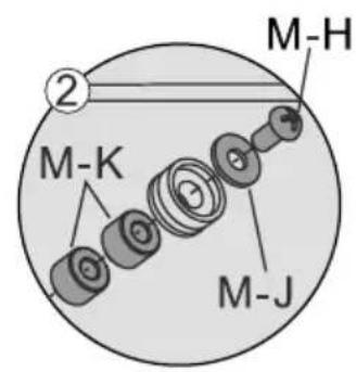
text_image
M-H ② M-K M-J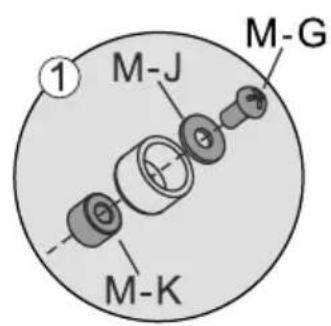
text_image
M-J M-G M-K
text_image
M-K M-J M-GNote: Choose the appropriate screws, washers and spacers (if necessary) according to the type of screen. Screw the VESA plate onto the TV.
Tighten all screws but do not over tighten.
3. Hanging the TV onto the Wall Plate
GB
flowchart
graph TD
    A["Key Hole Openings"] --> B["Device 1: Screen with circular head"]
    A --> C["Device 2: Screen with circular head"]
    A --> D["Device 3: Screen with circular head"]
    E["Diagram: Opening of key holes"] --> F["Arrow pointing to the process"]
    G["Arrow pointing to the process"] --> H["Arrow pointing to the process"]
After the wall mount has been safely secured to the wall, Carefully lift your TV so that top adapter brackets fit into key hole openings. Slide down wall plate into place. Make sure your TV is securely and correctly attached.
Maintenance
- Check that the bracket is secure and safe to use at regular intervals (at least every three months).
- Please contact your dealer if you have any questions.
Technical Information
GB

text_image
86 mm min 100 mm - max 800 mm 14 mm min 100 mm - max 600 mm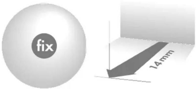
text_image
fix 14mm
text_image
50 kg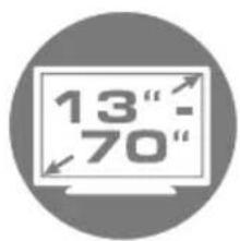
text_image
13" - 70"
text_image
max. 178 cm
text_image
VESA max. 800