
Profile PP989TNWW - Piekarnik GE - Bezpłatna instrukcja obsługi
Znajdź bezpłatnie instrukcję urządzenia Profile PP989TNWW GE w formacie PDF.

| Producent | GE |
| Model | Profile PP989TNWW |
| Typ produktu | Płyta grzewcza z systemem wyciągu powietrza (downdraft) |
| Liczba stref grzewczych | 5 (w tym 1 podwójna i 1 mostkowa) |
| Zasilanie | 120/240 V, 60 Hz, 9,1 kW (lub 120/208 V, 6,9 kW) |
| Wymiary (szer. x głęb. x wys.) | 76,2 cm x 53,3 cm x 7,6 cm (przybliżone) |
| Materiał powierzchni | Szkło ceramiczne |
| System wyciągu | Wbudowany wyciąg z regulacją prędkości (HI/MED/LO) |
| Blokada sterowania | Tak (Control Lock) |
| Wskaźniki | Wskaźnik włączenia strefy, wskaźnik gorącej powierzchni |
| Ogranicznik temperatury | Tak (chroni szkło przed przegrzaniem) |
| Funkcje specjalne | Strefa podwójna (6"/9"), strefa mostkowa, możliwość łączenia stref |
| Czyszczenie | Zalecany środek CERAMA BRYTE® i specjalna gąbka |
| Filtr wyciągu | Model WB02X10651 (można myć w wodzie z mydłem) |
| Akcesoria | Środek czyszczący WX10X300, skrobak WX10X0302 |
| Gwarancja | 1 rok (części i robocizna), 5 lat na powierzchnię szklaną i elementy grzewcze |
| Instalacja | Wymagany jest profesjonalny montaż; podłączenie do instalacji wentylacyjnej na zewnątrz |
Często zadawane pytania - Profile PP989TNWW GE
Pytania użytkowników dotyczące Profile PP989TNWW GE
0 pytanie dotyczące tego urządzenia. Odpowiedz na te, które znasz, lub zadaj własne.
Zadaj nowe pytanie dotyczące tego urządzenia
Pobierz instrukcję dla swojego Piekarnik w formacie PDF za darmo! Znajdź swoją instrukcję Profile PP989TNWW - GE i weź swoje urządzenie elektroniczne z powrotem w ręce. Na tej stronie opublikowane są wszystkie dokumenty niezbędne do korzystania z urządzenia. Profile PP989TNWW marki GE.
INSTRUKCJA OBSŁUGI Profile PP989TNWW GE
Radiant Downdraft Cooktop
Safety Instructions....2-3
Operating Instructions
Bridge Burner 6
Cooktop Vent System 6
Cookware Tips 7
Dual Surface Unit 6
Features of Your Cooktop ..... 4
Surface Units 5,6
Temperature Limiter 6
Care and Cleaning
Control Knobs 8
Glass Cooktop....9,10
Vent Filter and Chamber ..... 8
Vent Grille 8
Installation Instructions
Ductwork....15-18,22
Electrical Connections ..... 22-24
Exhaust Blower Ratings ..... 17
Final Assembly 25
Installing the Cooktop ..... 20–22
Installing the Gasket 19
Preparation....13-15
Safety Precautions 11
Unpacking the Cooktop ..... 12, 19
Troubleshooting Tips .....26
Consumer Support
Consumer Support 30
Warranty 29
Write the model and serial numbers here:
Model # ____
Serial # ____
Find these numbers on a label under the cooktop, on the side of the vent chamber.
Owner's Manual & Installation Instructions
PP989
WARNING
Read all safety instructions before using the product. Failure to follow these instructions may result in fire, electric shock, serious injury or death.
WARNING
GENERAL SAFETY INSTRUCTIONS
Use this appliance for its intended purpose as described in this Owner's Manual.
- Be sure your appliance is properly installed and grounded by a qualified installer in accordance with the provided installation instructions.
Do not attempt to repair or replace any part of your range unless it is specifically recommended in this manual. All other servicing should be referred to a qualified technician.
Before performing any service, unplug the cooktop or disconnect the power supply at the household distribution panel by removing the fuse or switching off the circuit breaker.
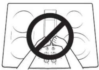
Do not leave children alone—children should not be left alone or unattended in an area where an appliance is in use. They should never be allowed to climb, sit or stand on any part of the appliance.
■ CAUTION: Do not store items of interest to children above a cooktop—children climbing on the cooktop to reach items could be seriously injured.
Use only dry pot holders—moist or damp pot holders on hot surfaces may result in burns from steam. Do not let pot holders touch hot surface units or heating elements. Do not use a towel or other bulky cloth in place of pot holders.
- Never use your appliance for warming or heating the room.
Do not touch the surface elements. These surfaces may be hot enough to burn even though they are dark in color. During and after use, do not touch, or let clothing or other flammable materials contact the surface units or areas nearby the surface units; allow sufficient time for cooling first. Other surfaces of the appliance may become hot enough to cause burns. Potentially hot surfaces include the cooktop and areas facing the cooktop.
Do not heat unopened food containers. Pressure could build up and the container could burst, causing an injury.
Cook meat and poultry thoroughly—meat to at least an internal temperature of 160° F and poultry to at least an internal temperature of 180° F. Cooking to these temperatures usually protects against foodborne illness.
WARNING
KEEP FLAMMABLE MATERIALS AWAY FROM THE COOKTOP.
Do not store or use flammable material near the cooktop, including paper, plastic, pot holders, linens, wall coverings, curtains, drapes and gasoline or other flammable vapors and liquids.
- Never wear loose-fitting or hanging garments while using the appliance. These garments may ignite if they contact hot surfaces causing severe burns.
Do not let cooking grease or other flammable materials accumulate on or near the cooktop. Grease on the cooktop may ignite.
- Clean ventilating hoods frequently. Grease should not be allowed to accumulate on the hood or filter.
WARNING
IN THE EVENT OF A FIRE, TAKE THE FOLLOWING STEPS TO PREVENT THE FIRE FROM SPREADING:
Do not use water on grease fires. Never pick up a flaming pan. Turn the controls off. Smother a flaming pan on a surface unit by covering the pan completely with a well-fitting lid, cookie sheet or flat tray. Use a multi-purpose dry chemical or foam-type fire extinguisher.
WARNING
RADIANT COOKTOP SAFETY INSTRUCTIONS
Never leave the surface units unattended at medium or high heat settings. Boilovers cause smoking and greasy spillovers that may catch on fire.
Never leave oil unattended while frying. If allowed to heat beyond its smoking point, oil may ignite resulting in fire that may spread to surrounding cabinets. Use a deep fat thermometer whenever possible to monitor oil temperature.
To avoid oil spillover and fire, use a minimum amount of oil when shallow pan-frying and avoid cooking frozen foods with excessive amounts of ice.
Use proper pan size—select cookware having flat bottoms large enough to cover the surface heating element. The use of undersized cookware will expose a portion of the surface unit to direct contact and may result in ignition of clothing. Proper relationship of cookware to surface unit will also improve efficiency.
Only certain types of glass, glass/ceramic, earthenware or other glazed containers are suitable for cooktop service; others may break because of the sudden change in temperature.
To minimize the possibility of burns, ignition of flammable materials and spillage, the handle of a container should be turned toward the center of the range without extending over nearby surface units.
- When preparing flaming foods under a hood, turn the fan on.
Use care when touching the cooktop. The glass surface of the cooktop will retain heat after the controls have been turned off.
Avoid scratching or impacting the glass cooktop. Doing so may lead to broken glass. The cooktop can be scratched with items such as knives, sharp instruments, rings or other jewelry, and rivets on clothing.
Do not cook on a broken cooktop. If glass cooktop should break, cleaning solutions and spillovers may penetrate the broken cooktop and create a risk of electric shock. Contact a qualified technician immediately.
Do not place or store items that can melt or catch fire on the glass cooktop, even when it is not being used. If the cooktop is inadvertently turned on, they may ignite. Heat from the cooktop after it is turned off may cause them to ignite also.
Use CERAMA BRYTE® ceramic Cooktop Cleaner and CERAMA BRYTE® Cleaning Pad to clean the cooktop. Wait until the cooktop cools and the indicator light goes out before cleaning. A wet sponge or cloth on a hot surface can cause steam burns. Some cleaners can produce noxious fumes if applied to a hot surface. Note: Sugar spills are an exception. They should be scraped off while still hot using an oven mitt and a scraper. See the Cleaning the glass cooktop section for detailed instructions.
Read and follow all instructions and warnings on the cleaning cream label.
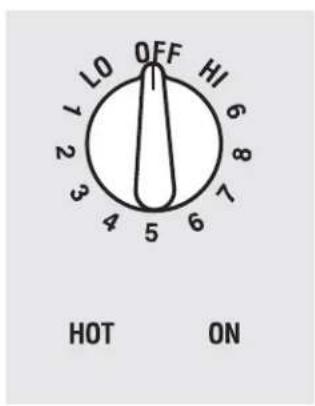
Features of Your Cooktop.
Throughout this manual, features and appearance may vary from your model.

Feature Index (Features and appearance may vary)
1 Left Rear Surface Unit
2 Bridge Surface Unit
3 Left Front Surface Unit
4 Vent Grille
5 Vent Filter (below the vent grille)
6 Right Rear Surface Unit
7 Dual Surface Unit
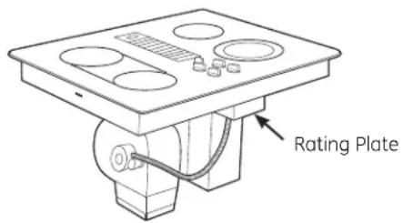
8 Model and Serial Number Label (under the cooktop, on the right side of the vent chamber)
9 Left Rear Surface Unit Control
10 Left Front Surface Unit Control
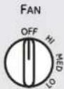
11 Left Side Hot Surface Indicator Lights (one for each surface unit)
12 Vent Fan Speed Control
13 Control Lock Knob
14 Right Side Hot Surface Indicator Lights (one for each surface unit)
15 Dual Surface Unit Control
16 Right Rear Surface Unit Control
17 Surface Unit On Indicator Light
![graph TD A["9"] --> B["OFF"] B --> C["10"] C --> D["11"] D --> E["12"] E --> F["13"] F --> G["CONTROL LOCK UNLOCK Lock"] H["14"] --> I["ON"] I --> J["15"] J --> K["16"] K --> L["17"] style A fill:#f9f,stroke:#333 style B fill:#ccf,stroke:#333 style C fill:#cfc,stroke:#333 style D fill:#fcc,stroke:#3…](/content/2026/06/1168268/images/26086556f4cf69174ecc2457a92846456cd08e8df672bea3ab92db539af29d3f.jpg)

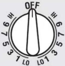
Be sure you turn the control knob to OFF when you finish cooking.
Radiant Surface Units
The control for the radiant surface unit can be set anywhere between LO and HI for an unlimited number of heat settings. With the infinite switch the coil cycles on and off to maintain your selected control setting.
To bring liquids to a boil faster, use a lid to cover the pan.
The control knob must be pushed down and turned from the OFF position. When the control knobs are in any position other than off, they may be turned without pushing down.
Be sure you turn the control knob off when you finish cooking. You will feel a click at the OFF position.
The surface unit ON indicator light will glow when any surface unit is on.
The HOT surface indicator light will glow when the glass surface is hot and will remain on until the surface has cooled.

Never cook directly on the glass. Always use cookware.
About the radiant surface units...
The radiant cooktop features heating units beneath a smooth glass surface.
NOTE: A slight odor is normal when a new cooktop is used for the first time. It is caused by the heating of new parts and insulating materials and will disappear in a short time.
NOTE: On models with light colored glass cooktops, it is normal for the cooking zones to change color when hot or cooling down. This is temporary and will disappear as the glass cools to room temperature.
The surface unit will cycle on and off to maintain your selected control setting.
It is safe to place hot cookware from the oven or surface on the glass surface when the surface is cool.
Water stains (mineral deposits) are removable using the cleaning cream or full strength white vinegar.
Use of window cleaner may leave an iridescent film on the cooktop. The cleaning cream will remove this discoloration.
- Don't store heavy items above the cooktop. If they drop onto the cooktop, they can cause damage.
Do not use the surface as a cutting board.

Always place the pan in the center of the surface unit you are cooking on.
Even after the surface units are turned off, the glass cooktop retains enough heat to continue cooking. To avoid over-cooking, remove pans from the surface units when the food is cooked. Avoid placing anything on the surface unit until it has cooled completely.

Do not slide cookware across the cooktop because it can scratch the glass. The glass is scratch-resistant, not scratchproof.
Using the surface units.
 Small 6" → surface unit settingLarge 9" → surface unit setting Small 6" → surface unit settingLarge 9" → surface unit setting | Dual Surface UnitThe right front surface unit has 2 cooking sizes to select from so you can match the size of the unit to the size of the cookware you are using.To use the large (9-inch) surface unit, turn the knob clockwise to and select the desired setting. The unit will heat the entire area contained by the larger circle. | To use the small (6-inch) surface unit, turn the knob counterclockwise to and select the desired setting. The unit will only heat the area inside the smaller circle. |
 Front Burner onlyFront Burner and Bridge Front Burner onlyFront Burner and Bridge | Bridge Surface UnitMake sure the pan rests flat on the glass cooktop and it is not resting on the trim. If you notice poor cooking performance, move the pan to make sure it is flat on the cooktop.To use the bridge burner, turn the burner knob to and select the desired setting. The unit will heat the front surface burner and the bridge. | Choose pans that match the circle/bridge area as closely as possible.To use only the front surface unit, turn the burner knob to and select the desired setting. The unit will only heat the front surface burner.You can create an oblong heated area by using the left rear unit in addition to the front unit bridge combination. |
| Surface Elements Cycle On and OffSurface elements will cycle on and off to maintain the temperature you have selected.All radiant surface elements have a temperature limiter that protects the glass cooktop from getting too hot. | The temperature limiter may cycle the elements off while cooking if:The pan boils dryThe pan bottom is not flat.The pan is off-center.There is no pan on the element. | |
| Temperature LimiterEvery radiant surface unit has a temperature limiter.The temperature limiter protects the glass cooktop from getting too hot. | The temperature limiter may cycle the units off for a time if:The cooktop is on while cooking.The pan boils dry.The pan bottom is not flat.The pan is off-center.There is no pan on the unit. | |
 | Control Lock-Out for Surface UnitsTo activate control lock-out, turn the Control Lock knob to LOCK. This will prevent surface units from heating. An indicator light will glow to show that they are locked. The downdraft fan will remain operable with control lockout engaged. | In the locked position, the cooktop will produce an audible sound if any surface unit control knob is engaged or moved to a position other than OFF. |
 | How to Operate the Vent SystemThe built-in vent system helps remove cooking vapors, odors and smoke from foods prepared on the cooktop.To operate the downdraft vent system, turn the vent fan speed control knob to HI, MED or LO, as needed. | Continuous use of the vent system while cooking helps keep the kitchen comfortable and less humid, reducing cooking odors and soiling moisture that normally creates a frequent need for cleaning. |
Selecting types of cookware
for glass cooktop models. (on non-induction models) GEAppliances.com
The following information will help you choose cookware which will give good performance on glass cooktops. See insert for cookware to use with induction cooktops.
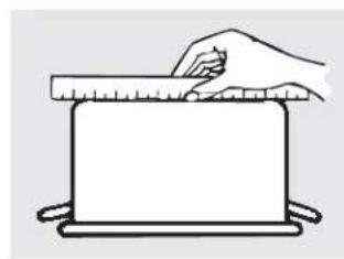
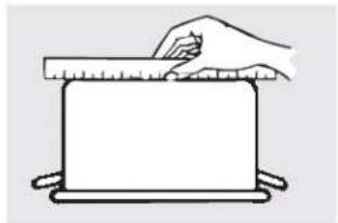
Check pans for flat bottoms by using a straight edge.
Stainless Steel:
recommended
Porcelain Enamel on Cast Iron:
recommended if bottom of pan is coated
Aluminum:
heavy weight recommended
Good conductivity. Aluminum residues sometimes appear as scratches on the cooktop but can be removed if cleaned immediately. Because of its low melting point, thin weight aluminum should not be used.
Porcelain Enamel on Steel:
not recommended
Heating empty pans can cause permanent damage to cooktop glass. The enamel can melt and bond to the ceramic cooktop.
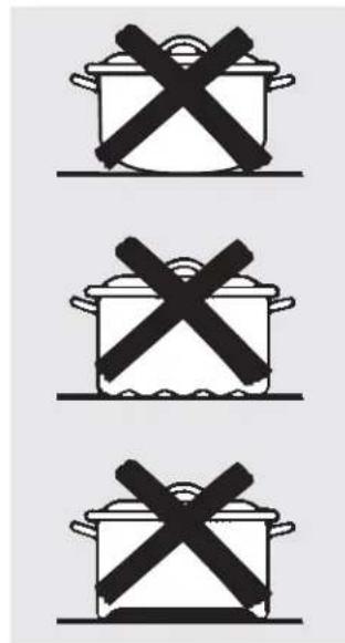
Pans with rounded, curved, ridged or warped bottoms are not recommended.
Copper Bottom:
recommended
Copper may leave residues which can appear as scratches. The residues can be removed, as long as the cooktop is cleaned immediately. However, do not let these pots boil dry. Overheated metal can bond to glass cooktops. An overheated copper bottom pot will leave a residue that will permanently stain the cooktop if not removed immediately.
Glass-ceramic:
not recommended
Poor performance. Will scratch the surface.
Stoneware:
not recommended
Poor performance. May scratch the surface.
Cast Iron:
not recommended—unless designed specifically for glass cooktops
Poor conductivity and slow to absorb heat. Will scratch the cooktop surface.
NOTE: Follow all cookware manufacturer's recommendations when using any type of cookware on the ceramic cooktop.

For Best Results
Place only dry pans on the surface elements. Do not place lids on the surface elements, particularly wet lids.
Do not use woks that have support rings. This type of wok will not heat on glass surface elements.
We recommend that you use only a flat-bottomed wok. They are available at your local retail store. The bottom of the wok should have the same diameter as the surface element to ensure proper contact.
Some special cooking procedures require specific cookware such as pressure cookers, deep-fat fryers, etc. All cookware must have flat bottoms and be the correct size.
Avoid allowing foods to boil dry as some cookware may stick to the cooking surface, causing permanent damage to the cooktop.
Care and cleaning of the cooktop.
Be sure electrical power is off and all surfaces are cool before cleaning any part of the cooktop.
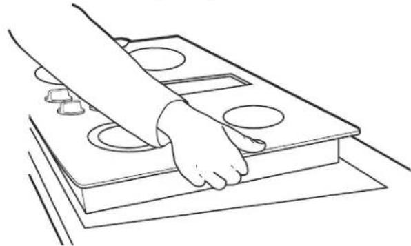
How to Remove Protective Shipping Film and Packaging Tape
Carefully grasp a corner of the protective shipping film with your fingers and slowly peel it from the appliance surface. Do not use any sharp items to remove the film. Remove all of the film before using the appliance for the first time.
To assure no damage is done to the finish of the product, the safest way to remove the adhesive from packaging tape on new appliances is an application of a household liquid dishwashing detergent. Apply with a soft cloth and allow to soak.
NOTE: The adhesive must be removed from all parts. It cannot be removed if it is baked on.

Vent Grille
Before cleaning the vent grille, be sure the exhaust blower is turned off.
Use dishwashing liquid for cleaning.
Do not use abrasive cleaners. They will damage the vent grille's finish.
To clean the vent grille, remove it from the cooktop by lifting it up and off. Wipe with a damp cloth. If necessary, the vent grille can be washed in the sink.
Do not clean the vent grille in the dishwasher.
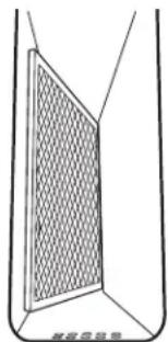
Vent Filter and Chamber
The filter is held in place at an angle with a hold bump. Lift the filter up and out of the vent opening diagonally.
Do not operate the vent without the filter in place.
To clean the filter, swish it in hot, soapy water. Rinse well and dry thoroughly.
Do not operate the vent without the filter in place.


Remove and replace the filter diagonally through the vent opening.
When replacing the filter, make sure it rests, at an angle, on the supports in the vent opening.
To order filters please call our toll-free number:
To clean the vent chamber, use hot, soapy water. Rinse with clean water and dry thoroughly. Do not use abrasive cleaners; they will damage the finish. Replace the filter after it is cleaned and dry.
National Parts Center.....800.626.2002 Filter.....# WB02X10651
Control Knobs
The control knobs may be removed for easier cleaning.
To clean the knobs, place them in a dishwasher or wash with soap and water. Rinse with clean water. Make sure the insides of knobs are dry before replacing.
Make sure the knobs are in the OFF positions and pull them straight off the stems for cleaning.
Replace the knobs in the OFF position to ensure proper placement.
Stainless Steel Surfaces (on some models)
Do not use a steel wool pad; it will scratch the surface.
To inquire about purchasing stainless steel appliance cleaner or polish, or to find the location of a dealer nearest you, please call our toll-free number:
To clean the stainless steel surface, use warm sudsy water or a stainless steel cleaner or polish. Always wipe the surface in the direction of the grain. Follow the cleaner instructions for cleaning the stainless steel surface.
National Parts Center 1.800.626.2002
GEAppliances.com
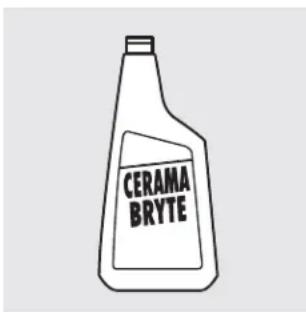
Clean your cooktop after each spill. Use CERAMA BRYTE® Ceramic Cooktop Cleaner.
Normal Daily Use Cleaning
ONLY use CERAMA BRYTE® Ceramic Cooktop Cleaner on the glass cooktop. Other creams may not be as effective.
To maintain and protect the surface of your glass cooktop, follow these steps:
Before using the cooktop for the first time, clean it with CERAMA BRYTE® Ceramic Cooktop Cleaner. This helps protect the top and makes clean-up easier.
Daily use of CERAMA BRYTE® Ceramic Cooktop Cleaner will help keep the cooktop looking new.
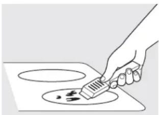
3 Shake the cleaning cream well. Apply a few drops of CERAMA BRYTE® Ceramic Cooktop Cleaner directly to the cooktop.
4 Use a paper towel or CERAMA BRYTE® Cleaning Pad for Ceramic Cooktops to clean the entire cooktop surface.
5 Use a dry cloth or paper towel to remove all cleaning residue. No need to rinse.
NOTE: It is very important that you DO NOT heat the cooktop until it has been cleaned thoroughly.

Use a CERAMA BRYTE ® Cleaning Pad for Ceramic Cooktops or a Scotch-Brite ® Multi-Purpose No Scratch blue scrub pad.
Burned-On Residue
WARNING: DAMAGE to your glass surface may occur if you use scrub pads other than the pad included with your cooktop.
1 Allow the cooktop to cool.
2 Spread a few drops of CERAMA BRYTE® Ceramic Cooktop Cleaner to the entire burned residue area.
3 Using the included CERAMA BRYTE® Cleaning Pad for Ceramic Cooktops, rub the residue area, applying pressure as needed.
4 If any residue remains, repeat the steps listed above as needed.
For additional protection, after all residue has been removed, polish the entire surface with CERAMA BRYTE® Ceramic Cooktop Cleaner and a paper towel.
The CERAMA BRYTE® Ceramic Cooktop Scraper and all recommended supplies are available through our Parts Center. See instructions under "To Order Parts" section on next page. NOTE: Do not use a dull or nicked blade.
Heavy, Burned-On Residue
1 Allow the cooktop to cool.
2 Use a single-edge razor blade scraper at approximately a 45° angle against the glass surface and scrape the soil. It will be necessary to apply pressure to the razor scraper in order to remove the residue.
3 After scraping with the razor scraper, spread a few drops of CERAMA BRYTE® Ceramic Cooktop Cleaner to the entire burned residue area. Use the CERAMA BRYTE® Cleaning Pad to remove any remaining residue.
For additional protection, after all residue has been removed, polish the entire surface with CERAMA BRYTE® Ceramic Cooktop Cleaner and a paper towel.
Metal Marks and Scratches
1 Be careful not to slide pots and pans across your cooktop. It will leave metal markings on the cooktop surface. These marks are removable using the CERAMA BRYTE® Ceramic Cooktop Cleaner with the CERAMA BRYTE® Cleaning Pad for Ceramic Cooktops.
2 If pots with a thin overlay of aluminum or copper are allowed to boil dry, the overlay may leave black discoloration on the cooktop. This should be removed immediately before heating again or the discoloration may be permanent.
WARNING: Carefully check the bottom of pans for roughness that would scratch the cooktop.
Glass surface—potential for permanent damage.
Our testing shows that if you are cooking high sugar mixtures such as jelly or fudge and have a spillover, it can cause permanent damage to the glass surface unless the spillover is immediately removed.
Damage from Sugary Spills and Melted Plastic
1 Turn off all surface units. Remove hot pans.
3 Any remaining spillover should be left until the surface of the cooktop has cooled.
2 Wearing an oven mitt: a. Use a single-edge razor blade scraper (CERAMA BRYTE® Ceramic Cooktop Scraper) to move the spill to a cool area on the cooktop.
4 Don't use the surface units again until all of the residue has been completely removed.
b. Remove the spill with paper towels.
NOTE: If pitting or indentation in the glass surface has already occurred, the cooktop glass will have to be replaced. In this case, service will be necessary.
To Order Parts
To order CERAMA BRYTE® Ceramic Cooktop Cleaner and the cooktop scraper, please call our toll-free number:
National Parts Center 800.626.2002
CERAMA BRYTE®
Ceramic Cooktop Cleaner .. # WX10X300
CERAMA BRYTE®
Ceramic Cooktop Scraper . . # WX10X0302
Kit ....# WB64X5027
(Kit includes cream and razor scraper)
CERAMA BRYTE® Cleaning Pads for
Ceramic Cooktops .....#WX10X350
Installation Instructions
Radiant Downdraft Cooktop
If you have questions, call 800.GE.CARES (800.432.2737) or visit our Website at: GEAppliances.com
BEFORE YOU BEGIN
Read these instructions completely and carefully.
- IMPORTANT – Save these instructions for local inspector's use.
- IMPORTANT – Observe all governing codes and ordinances.
- Note to Installer – Be sure to leave these instructions with the Consumer.
- Note to Consumer – Keep these instructions for future reference.
- Unless very knowledgeable in the installation of this product, engage a professional installer.
- Proper installation is the responsibility of the installer.
- Product failure due to improper installation is not covered under the Warranty.

WARNING – Before beginning the installation, switch power off at the service panel and lock the service disconnecting means to prevent power from being switched on accidentally. When the service disconnecting means cannot be locked, securely fasten a prominent warning device, such as a tag, to the service panel.
IMPORTANT SAFETY INSTRUCTIONS

WARNING- TO REDUCE THE RISK OF FIRE, ELECTRIC SHOCK OR INJURY TO PERSONS, OBSERVE THE FOLLOWING:
A Installation work and electrical wiring must be done by qualified person(s) in accordance with all applicable codes and standards, including fire-rated construction.
B Sufficient air is needed for proper combustion and exhausting of gases through the flue (chimney) of fuel burning equipment to prevent back drafting. Follow the heating equipment manufacturer's guidelines and safety standards such as those published by the National Fire Protection Association (NFPA), and the American Society for Heating, Refrigeration and Air Conditioning Engineers (ASHRAE), and the local code authorities.
C When cutting or drilling into wall or ceiling, do not damage electrical wiring and other hidden utilities.
D Ducted fans must always be vented to the outdoors.
- This unit must be properly grounded.

WARNING - TO REDUCE THE RISK OF FIRE, USE ONLY METAL DUCTWORK.
UNPACKING YOUR COOKTOP
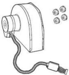
PARTS INCLUDED (PACKED BELOW THE COOKTOP)
- Blower assembly
- Blower plenum
• (4) Nuts (10-32 keps – nuts with lock washers attached)
• (9) Sheet metal screws (8-18 × 3/8")
• Foam gasket tape (9 ft. roll)
- Vent grille
- Vent filter
- Cleaning cream
- Scrub sponge or scraper (on some models)
Check to be sure that all packing materials and tape have been removed. This will include tape on control knobs (if applicable), adhesive tape, wire ties, cardboard and protective plastic. Failure to remove these materials could result in damage to the appliance once the appliance has been turned on and surfaces have heated.

Vent Grille

Sheet Metal Screws (9) (8-18 x 3/8")
Cleaning Cream

Scrub Sponge

Foam Gasket Tape
CAUTION: DO NOT LIFT FROM VENT OPENING OR BUMP GLASS

CAUTION: GLASS IS FRAGILE DO NOT UMP EDGE OF GLASS DURING INSTALLATION
Blower Assembly and (4) Mounting Nuts (10-32 keps – nuts with lock washers attached)

Blower Plenum

Vent Filter
PREPARATION
TOOLS AND MATERIALS YOU WILL NEED
- Saw
- Flat-blade screwdriver
- Electrician's pliers
- Duct tape
• Measuring tape or scale - Carpenter's square
• 7/16" wrench or socket set - Drill and drill bit
- Sheet metal screws
- Junction box*
- 3/4" flexible conduit*
• Electrical wire per local code* - Wire nuts*
- Ductwork
* NOTE: Electrical installation kit JXCK89 may be ordered separately and includes all the parts necessary to connect the cooktop to typical rough-in wiring.
ELECTRICAL REQUIREMENTS
This appliance must be supplied with the proper voltage and frequency, as listed in these Installation Instructions, and connected to an individual, properly grounded branch circuit, protected by a 40-amp circuit breaker or time delay fuses.
All wire connections must be made in accordance with local codes and properly insulated. Check with your local utility for governing electrical codes and ordinances. In the absence of local electrical codes, the National Electrical Code, ANSI/NFPA No. 70 – Latest Edition, governing electric range installations, must be followed.
A copy of the National Electrical Code can be obtained by writing to:
National Fire Protection Association Batterymarch Park Quincy, MA 02260
Effective January 1, 1996, the National Electrical Code requires that new, but not existing, construction utilize a four-conductor connection to an electric range. When installing an electric range in new construction, follow the instructions in NEW CONSTRUCTION AND FOUR-CONDUCTOR BRANCH CIRCUIT CONNECTION.
You must use a three-wire, single-phase AC 208V/120 Volt or 240/120 Volt, 60 Hertz electrical system with separate ground. If you connect to aluminum wiring, properly installed connectors approved for use with aluminum wiring must be used.

CAUTION: FOR PERSONAL SAFETY, REMOVE HOUSE FUSE OR OPEN CIRCUIT BREAKER BEFORE PREPARING JUNCTION BOX.
30" COOKTOP (DIMENSIONS FOR REFERENCE ONLY)
Unit shown fully assembled.


Unit must be vented to the outside!
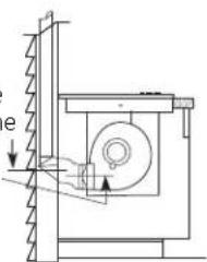
CABINET PREPARATION
1 PREPARING FOR INSTALLATION
Positioning the cooktop
The cooktop is designed to look best when centered in a cabinet at least 30" wide.
The exhaust vent beneath the cooktop must be located between wall studs or floor joists so that the ductwork may be installed properly.
At least 6" must be allowed between side edges of the cooktop and adjacent walls.
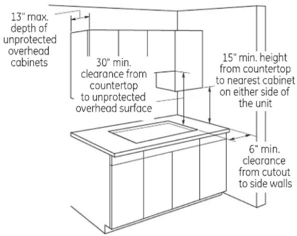
Avoid placing cabinets above the cooktop unit, if possible, in order to reduce the hazards caused by reaching over heated surface units. If cabinets are placed over the cooktop, the risks can be reduced by installing a range hood that projects horizontally a minimum of 5 inches beyond the bottom of the cabinets.
If cabinetry is used above the cooktop, allow a minimum 30" clearance between the cooking surface and the bottom of any unprotected cabinet.
If the clearance between the cooktop and the cabinetry is less than 30", the cabinet bottom must be protected with flame retardant millboard at least 1/4" thick, covered with 28 gauge sheet steel or 0.020" thick copper. Clearance between the cooktop and the protected cabinetry MUST NEVER BE LESS THAN 24".
EXCEPTION: Installation of a listed microwave oven or cooking appliance over the cooktop shall conform to the installation instructions packed with that appliance.
A 15" minimum must be kept from the side edge of the cooktop to the bottom of any cabinet not directly above the cooktop. If the clearance is less than 15", adjacent cabinets should be at least 6" from the side edge of the cooktop.
② PREPARING THE BASE CABINET
This cooktop is designed to fit easily into a variety of cabinets. However, some cabinets may require modifications.
Preparing a cabinet that is against a wall
In some cabinets, the sides may need to be scooped or cut down 5 3/4 " as shown, and the corner braces removed in order to accommodate the unit.
In 75 cm and 90 cm frameless European cabinets, the back panel may need to be cut down 5 3/4 " to accommodate the unit.
Preparing a peninsula or island-type cabinet
In a peninsula or island-type cabinet, the sides may need to be scooped or cut down, and the corner braces removed in order to accommodate the unit.

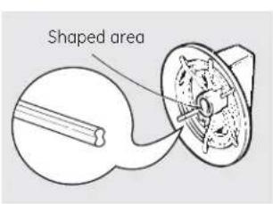
③ ROUGH PREPARATION OF JUNCTION BOX
A CAUTION: FOR PERSONAL SAFETY, REMOVE HOUSE FUSE OR OPEN CIRCUIT BREAKER BEFORE PREPARING JUNCTION BOX.
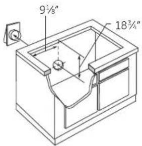
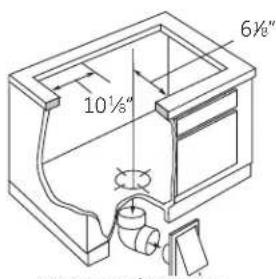
Install an approved junction box within shaded area shown in diagram. Junction box must be at least 10 1/2 " below top of cabinet.
Run conductors from residence wiring to junction box according to local electrical codes.

CABINET PREPARATION CUTOUTS
4 PREPARING THE COUNTERTOP
The countertop must have a deep flat surface to accommodate the cooktop and the vent. Countertops with a rolled front edge and backsplash may not provide the flat surface area required.

Clearance between inside front of cabinet and rear of countertop cutout must be 20 5/8 " in order to accommodate cooktop depth.

A 1/2" wide flat area is required around the edge of opening for support of the unit. The cooktop unit must be level and sit squarely into countertop opening.
Carefully cut countertop opening according to the dimensions shown in the illustration. Be sure that the opening is cut squarely, with sides parallel to each other and the rear exactly perpendicular to the sides.

5 PREPARING FOR DUCTWORK
NOTE: Ductwork MUST be vented to outside. DO NOT vent into a wall, ceiling, crawlspace, attic or any concealed space.
Cut hole in cabinet wall or floor as appropriate for your installation. Make sure exhaust duct is located between wall studs or floor joists.
NOTE: When cutting or drilling into wall or ceiling, do not damage electrical wiring and other hidden utilities.
Rear Wall Venting
Downward Venting
6 BLOWER TO DUCTWORK ALIGNMENT
In general, the use of flexible ducting is discouraged because it can cause severely restricted airflow. However, if the blower outlet and the floor or wall duct location do NOT align well, then flexible METAL ducting can be used to adapt to an offset. Good alignment without use of flexible ducting is best.
NOTE:
- Do not exceed the maximum recommended offset of 6".
- Do not allow the flexible ducting to kink or collapse.
- Do stretch the flexible ducting as much as possible to eliminate as much of the corrugation as possible.
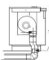
Bottom Venting
6" Max. Centerline to Centerline / Offset ↓
Back Venting (Requires 3¼" × 10")
A 3 1/4 " x 10" rectangle to 6" round transition duct is available at your local building supply store.
NOTE: Illustrations are for planning purposes only.
DUCTWORK CALCULATIONS
| Calculate Total Equivalent Ductwork Length | |||
| ==Equivalent =Number =Equivalent=Duct Pieces =Length* x =Used ==Length | |||
| ==5" round==straight=2.7 ft. = x = ( ft.) | == =ft. | ||
| ==6" round==straight=1 ft. = x = ( ft.) | == =ft. | ||
| ==straight=3 1/4 " × 10"1 ft. = x = (= ft.) | == =ft. | ||
| ==5", 90°==6", 90° | elbow | 37 ft. x () = | ft. |
| elbow | 12 ft. x () = | ft. | |
| ==5", 45°==6", 45° | elbow | 18 ft. x () = | =ft. |
| elbow | 7 ft. x () = | =ft. | |
| ==Flexible==metal offset==adapter | 34 ft. x = ( ) = | = | =ft. |
| [IMAGE] | 3 1/4 " × 10"90° elbow | 14 ft. x () = | ft. |
| [IMAGE] | 3 1/4 " × 10"45° elbow | 8 ft. x () = | ft. |
| [IMAGE] | 3 1/4 " × 10"90° flat elbow | 33 ft. x () = | =ft. |
| ==5" round= to 3==6" round= to 3 | 1/4 " × 10"transition | 3 ft. x () = | ft. |
| 1/4 " × 10"transition | 2 ft. x () = | ft. | |
| === Subtotal Column 1 ==ft.*Equivalent lengths of duct pieces are based on actual tests and reflect requirements for good venting performance with any downdraft cooktop.†Measure and list feet of straight duct used. Count and list the quantity of all other duct pieces for the "Number Used" of each type.IMPORTANT:For maximum efficiency, use the shortest and straightest duct run possible, with as few fittings as possible. For satisfactory performance, the duct run should not exceed 100 feet equivalent length.Venting performance is improved by using larger diameter duct. | |||
| ===Equivalent =Number =Equivalent=Duct Pieces =Length* x | Used ==Length | ||
| = | 5" round to 31⁄4" × 10" transition90° elbow | 37 ft. x ( ) = | ft. |
| = | |||
| = | 6" round to 31⁄4" × 10" transition90° elbow | 4 ft. x ( ) = | ft. |
| = | 31⁄4" × 10" to 6" round transition | 2 ft. x ( ) = | ft. |
| = | 31⁄4" × 10" to 6" round transition90° elbow | 4 ft. x ( ) = | =ft. |
| = | Tapered 5" round to 6" round transition | 6 ft. x ( ) = | =ft. |
| = | 5" round collar to 6" round transition | 13 ft. x ( ) = | =ft. |
| = | 5" round wall cap with damper | 84 ft. x ( ) = | ft. |
| = | 6" round wall cap with damper | 24 ft. x ( ) = | ft. |
| = | 31⁄4" × 10" wall cap with damper | 24 ft. x ( ) = | ft. |
| = | 6" round roof cap | 33 ft. x ( ) = | ft. |
| = Subtotal Column 2 == Subtotal Column 1 = =ft.TOTAL DUCTWORK = | =ft. | ||
| ft. | |||
| Should not exceed 100 feet.If flexible metal ducting is used, all the equivalent feet values in the table should be doubled. The flexible metal duct should be straight and smooth and extended as much as possible.DO NOT use flexible plastic ducting.Vent installation should not exceed 100 feet equivalent length. | |||
EXHAUST BLOWER RATINGS
EXHAUST BLOWER SAFETY WARNING
Sufficient air is needed for proper combustion and exhausting of gases through the flue (chimney) of other fuel burning equipment to prevent back drafting. Follow the heating equipment manufacturer's guidelines and safety standards such as those published by the National Fire Protection Association (NFPA), the American Society for Heating, Refrigeration and Air Conditioning Engineers (ASHRAE) and local code authorities.
DUCTWORK INSTALLATION
(Note: For planning purposes only.)
7 INSTALLING THE DUCTWORK
Use galvanized or aluminum duct in 6" round or 3 1/4 " x 10" size, or a combination of both.
PVC duct should be used if installing under a poured concrete slab.
NOTE: Local building code must be followed in specifying approved type and schedule of ALL duct used.
Always use an appropriate roof or wall cap with damper. Laundry-type wall caps should NEVER be used.

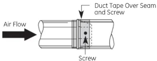
Install ductwork, making male-female connections in the direction of airflow as shown. Secure all joints with sheet metal screws and duct tape to assure an airtight seal.
Use the shortest and straightest duct run possible. For satisfactory performance, the duct run should not exceed 100 feet equivalent length. Refer to the "DUCTWORK CALCULATIONS" chart for equivalent lengths. Use this chart to calculate the total equivalent length of the ductwork.
OPTIONAL INSTALLATION: REAR WALL VENTING
5" round duct may be used on SHORT DUCT runs, but best results will be obtained using 31/4 " x 10" or 6" round ducting.

To convert blower exhaust direction, remove four nuts behind the filter which hold blower and wire finger guard.
Rotate blower and reinstall to vent chamber, as shown above. Retighten nuts, but do not overtighten.
UNPACKING THE COOKTOP/INSTALLING THE GASKET
8 INSTALLING THE FOAM GASKET
Do not install the cooktop into the countertop without installing the foam gasket as shown. It protects the bottom edge of the glass from the countertop and seals the cooktop against spills. Remove the cooktop along with its shipping pad from the shipping box. Remove the shipping block from the downdraft vent opening and place it under the shipping pad to provide level support.

Center vent shipping block – place under the shipping pad to provide level support
CAUTION: GLASS IS FRAGILE. DO NOT BUMP EDGE OF GLASS DURING INSTALLATION.
Locate the foam gasket tape included with your cooktop.

Peel off the white backing to install the foam gasket tape on the bottom side of the cooktop glass as shown.
Note: On stainless steel model PP989S, apply the foam tape around the outer edge of the glass only on the sides and rear of the unit.
Foam Gasket Installation Notes:
- The foam gasket tape should be installed within 1/8" of the edge of the glass. Do not stretch or twist the foam gasket tape.
CAUTION: Failure to install foam gasket tape greatly increases the potential of breaking the cooktop glass when installing, especially in Corian® or granite countertops.
- Use care not to stretch the foam gasket tape while it is installed or it will not stay in place.
- Do not place foam gasket tape over the metal flanges.
- Butt the foam gasket tape ends together at each corner without overlapping.
- Trim the foam gasket tape to length without stretching.
- Mitre cut outside corners of foam gasket tape slightly if necessary for appearance.

- Do not scratch the glass while cutting the foam gasket tape.
INSTALLING THE COOKTOP
INSTALLING THE COOKTOP

CAUTION:
DO NOT LIFT FROM VENT OPENING.
Lift the cooktop by the glass side edges as shown.
NOTE: Do not use the glass top vent opening to lift or move the cooktop into position.
Lower the cooktop into the countertop opening, guiding it into position. Glass is fragile—do not allow it to drop onto the countertop. Support from the underside and lower slowly.
Carefully remove your fingers one corner at a time to lower the cooktop into position.
NOTE: Do not use Silicone RTV or caulk to bond cooktop glass to countertop.
10 CHECKING FOR FLATNESS
Inspect the cooktop glass for rocking or uneven gap on all four sides at the countertop surface. Do not attempt to force the glass to meet the countertop.

11 INSTALLING THE OPTIONAL INSTALLATION BRACKETS
NOTE: Check for glass flatness in Step 10 before installing optional installation brackets.

To order optional installation brackets/thumbscrews, call the National Parts Center at 800.626.2002.
Order two of each part: WB02X11331 Bracket WB01X10353 Screw
To install optional installation brackets:
Remove 2 screws on both sides under cooktop.
Align optional installation bracket under cooktop and reinstall screws through the slot in the bracket. Do this on both sides of the cooktop.
Thread the thumbscrew through the hole in the bracket and tighten to secure the cooktop to the countertop. Repeat on the other side.
IMPORTANT: Turn thumbscrew until it touches the bottom of the countertop. Do not overtighten.
INSTALLING THE COOKTOP
12 INSTALLING THE BLOWER PLENUM TO THE COOKTOP
Slide the plenum, with the blower opening on the left, into the opening in the bottom of the cooktop. Push up on the plenum until the stops on the plenum contact the bottom of the cooktop, and snap the plenum into place. (You may have to move the plenum back and forth to work it into place.)
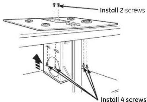
Secure the plenum to the bottom of the cooktop, on each side, using the four (4) screws provided. Further secure the plenum to the cooktop, from the top side, using the two screws (2) provided.
13 INSTALLING THE BLOWER TO THE PLENUM
Orient the blower discharge opening to match the ductwork in Steps 6 and 7. Slide the four threaded studs on the side of the blower housing into the four holes on the side of the plenum.
NOTE: See Step 14 for installing the transition duct to the blower. It may be easier to install the transition duct to the blower before installing the blower to the plenum.

From the vent opening in the top of the cooktop, fasten the blower assembly securely to the plenum with four (4) nuts.

INSTALLING THE COOKTOP
14 ATTACHING A BLOWER TRANSITION DUCT
Use a blower transition duct for all downward duct installations to connect to 6" round standard ductwork. This 3 1/4 " x 10" rectangle to 6" round transition duct is available at your local building supply store.

Remove the cardboard packing in the blower outlet. Install the transition duct to the blower outlet. Secure all joints with duct tape to assure an airtight seal.
15 CONNECTING THE DUCTWORK
Connect the ductwork prepared in Steps 5 and 6 to the blower transition duct.
16 BLOWER ELECTRICAL CONNECTIONS
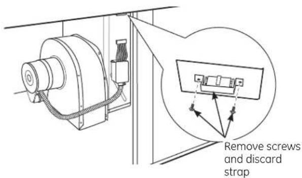
- Loosen the two screws and remove and discard the sheet metal strap covering the 5-pin connector on the cooktop bottom. Save the screws for reinstallation later.
16 BLOWER ELECTRICAL CONNECTIONS (cont.)
- Connect the 5-pin plug on the blower assembly to the matching 5-pin receptacle on the bottom of the wire enclosure.

Fold all wires into the electrical enclosure. Secure the enclosure with the screws removed earlier, making sure that no wires are trapped.

ELECTRICAL CONNECTIONS
17 BEFORE MAKING ELECTRICAL CONNECTIONS
Note to Electrician: The power leads supplied with this appliance are UL-recognized for connection to large gauge household wiring.
The insulation of these leads is rated at temperatures much higher than the temperature rating of household wiring. The current carrying capacity of a conductor is governed by the wire gauge and also the temperature rating of the insulation around the wire.
Aluminum Wiring - ⚠️WARNING: IMPROPER CONNECTION OF ALUMINUM HOUSE WIRING TO THE COPPER LEADS CAN RESULT IN SERIOUS PROBLEMS.
Attach copper wires to aluminum wiring using special connectors designed and UL-listed for joining copper to aluminum. Follow the connector manufacturer's recommended procedure closely.
Service Loop – Leave a loop in the wires to the cooktop so that the cooktop can be lifted 12 inches without having to disconnect the wiring.
ELECTRICAL REQUIREMENTS*
Model # Voltage Frequency KW
PP989 120/240V 60Hz 9.1KW
120/208V 60Hz 6.9KW
* For reference only. Verify with product rating plate.
Electrical installation kit JXCK89 may be ordered separately and includes all the parts necessary to connect the cooktop to typical rough-in wiring.
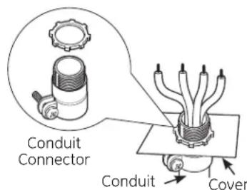
18 INSTALL 3/4" FLEXIBLE CONDUIT
Remove the screws holding the wire compartment cover and remove the cover.

Power Supply Leads
Anti-Short Bushing
Conduit
Bushing (Fully Seated)


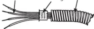
Feed the power supply leads through the conduit; be sure to leave enough length to properly connect these leads to the cooktop power leads.
Thread the leads through an anti-short bushing and firmly seat the bushing in the end of the conduit.
Feed the leads through the hole in the wire compartment.
As local codes permit purchase a listed conduit connector suitable for the size conduit. Insert the conduit through the connector and attach it to the cover. Allow enough slack to easily attach the wires to the cooktop.
Note: Do not install the cooktop without a listed conduit connector. The conduit connector should be installed before reinstalling the wiring cover.
When complete, reinstall the wire compartment cover.
ELECTRICAL CONNECTIONS
19 MAKING ELECTRICAL CONNECTIONS
Effective January 1, 1996, the National Electrical Code requires that new, but not existing, construction utilize a four-conductor connection to an electric range. When installing an electric range in new construction, follow the instructions in NEW CONSTRUCTION AND FOUR-CONDUCTOR BRANCH CIRCUIT CONNECTION.
You must use a three-wire, single-phase AC 208Y/120 Volt or 240/120 Volt, 60 Hertz electrical system with separate ground. If you connect to aluminum wiring, properly installed connectors approved for use with aluminum wiring must be used.
New construction and four-conductor branch circuit connection
- When installing in new construction, or
- When installing in a mobile home, or
- When local codes do not permit grounding through neutral:
4-Conductor Branch Circuit
When connecting the cooktop to a 4-conductor circuit, connect the red leads of the cooktop and the power supply to the branch circuit red lead; connect the black leads to each other. Connect the cooktop white lead to the power supply and branch circuit neutral leads, which are white or gray. Ground the unit by connecting the green conductor of the cooktop to the bare or green leads of the power supply and branch circuit (ground leads).
4-Conductor Branch Circuit
![graph TD A["120V AC"] --> B["NEUTRAL"] B --> C["Branch Circuit"] C --> D["Power Supply Leads"] D --> E["Cooktop Power Leads"] F["120V AC"] --> G["GND"] G --> H["Bare or Green"] H --> I["Bare or Green"] I --> J["Bare or Green"] J --> K["Bare or Green"] L["White or Gray"] --> M["Red"] N["White or Gray…](/content/2026/06/1168268/images/dd40efb1030f875c81d2ef0420fefd22012aec5e83aea42908072bce6ccd0596.jpg)
19 MAKING ELECTRICAL CONNECTIONS (cont.)
Three-conductor branch circuit connection
- When installing in existing construction built prior to January 1, 1996, and if permitted by local codes:
3-Conductor Branch Circuit
When connecting cooktop to a 3-conductor circuit, connect the red leads of the cooktop and the power supply to the branch circuit red lead; connect the black leads to each other. Connect the green and white leads of the cooktop to the power supply and branch circuit neutral leads, which are white or gray.
3-Conductor Branch Circuit
![graph LR A["120V AC"] --> B["NEUTRAL"] C["120V AC"] --> B B --> D["Branch Circuit"] D --> E["Power Supply Leads"] E --> F["Cooktop Power Leads"] D --> G["Red"] D --> H["White or Gray"] D --> I["Black"] E --> J["Red"] E --> K["White or Gray"] E --> L["Black"] F --> M["Red"] F --> N["White"] F --> O["…](/content/2026/06/1168268/images/55199ee1efa592de457eb2694dad8e2c720131af1bc50f8681290c8189610368.jpg)
FINAL ASSEMBLY
20 INSTALL DOWNDRAFT FILTER AND VENT GRILLE
Do not operate the vent without the filter in place.
- Place the filter diagonally through the vent opening.

- Make sure it rests, at an angle, on the supports in the vent opening.
- Carefully place the vent grille onto the downdraft opening.
CHECK OPERATION OF DOWNDRAFT
- Turn the vent fan speed control to HI, MED and LO to make sure all speeds operate correctly.
Before you call for service...
Troubleshooting Tips—Save time and money! Review this chart first and you may not need to call for service.
| Problem Possible Causes What To Do | ||
| Water won't boil • Cover pan with a lid.• Turn the downdraft fan OFF until the water begins to boil. | ||
| Surface units will not maintain a rolling boil or cooking is slow | Improper cookware being used. | • Pan bottoms should be flat, fairly heavyweight and the same diameter as the surface unit selected. |
| Surface units do not work properly | A fuse in your home may be blown or the circuit breaker tripped. | • Replace the fuse or reset the circuit breaker. |
| Cooktop controls improperly set. | • Check to see the correct control is set for the surface unit you are using. | |
| Tiny scratches or metal marks (may appear as cracks) or abrasions on radiant cooktop glass surface | Incorrect cleaning methods being used. | • See the Cleaning the glass cooktop section. |
| Cookware with rough bottoms being used or coarse particles (salt or sand) were between the cookware and the surface of the cooktop. | • Be sure cookware bottoms and cookware are clean before use. Use cookware with smooth bottoms. Tiny scratches are not removable but will become less visible in time as a result of cleaning. | |
| Cookware has been slid across the cooktop surface. | ||
| Areas of discoloration or dark streaks on the cooktop | Improper cookware being used. | • Marks from aluminum and copper pans as well as mineral deposits from water or food can be removed with the cleaning cream. |
| Hot surface on a model with a light-colored cooktop. | • This is normal. The surface may appear discolored when it is hot. This is temporary and will disappear as the glass cools. | |
| Food spillovers not cleaned before next use. | • See the Cleaning the glass cooktop section. | |
| Incorrect cleaning methods being used. | • Use recommended cleaning procedures. | |
| Hot sugar mixtures or plastic melted to the surface | Hot cooktop came into contact with these substances. | • See the Glass surface—potential for permanent damage section in the Cleaning the glass cooktop section. |
| Pitting (or indentation) of the cooktop | Hot sugar mixture spilled or plastic melted on the cooktop. | • Call a qualified technician for replacement. |
| Cooktop making an audible sound | Cooktop is locked. | • Check to be sure the Control Lock knob is turned to UNLOCK. |
| Frequent cycling off and on of surface units | Improper cookware being used. | • Use only flat cookware to minimize cycling. |
| Cooktop feels hot | Improper cookware being used. | • The glass cooktop surface may seem hotter than you are used to. This is normal. Use pans which are absolutely flat. |
| Control knob will not turn | Cooktop controls improperly set. | • When the knob is in the OFF position, it must be pushed down before it can be turned. When the knob is in any other position, it can be turned without being pushed in. |
| Poor venting | Clogged filter. | • Clean filter per instructions. |
| House too airtight. | • Open a window slightly to provide fresh air source. | |
| Wall cap obstructed. | • Remove blockage from exterior wall cap. | |
| Wall cap damper door stuck. | • Check exterior wall cap damper door for free movement or obstruction. | |
| Duct length exceeds recommended 100 equivalent foot maximum. | • Reduce number of elbows to simplify duct run. | |
Notes.
GE Electric Cooktop Warranty.

All warranty service provided by our Factory Service Centers, or an authorized Customer Care ® technician. To schedule service, on-line, visit us at GEAppliances.com, or call 800.GE.CARES (800.432.2737). Please have serial number and model number available when calling for service.
Staple your receipt here. Proof of the original purchase date is needed to obtain service under the warranty.
For The Period Of: GE Will Replace:
One Year
From the date of the
original purchase
Any part of the cooktop which fails due to a defect in materials or workmanship. During this limited one-year warranty, GE will also provide, free of charge, all labor and in-home service to be the defective part.
Five Years
From the date of the
original purchase
A replacement glass cooktop if it should: crack due to thermal shock; discolor; or if the
pattern wears off.
A replacement radiant surface unit if it should burn out.
During this limited additional four-year warranty, you will be responsible for any labor or
in-home service.
What GE Will Not Cover:
■ Service trips to your home to teach you how to use the product.
- Improper installation, delivery or maintenance.
Product damage or failure of the product if it is abused, misused, modified, used for other than the intended purpose, or used commercially.
■ Damage to the glass cooktop caused by use of cleaners other than the recommended cleaning creams and pads.
Damage to the glass cooktop caused by hardened spills of sugary materials or melted plastic that are not cleaned according to the directions in the Owner's Manual.
■ Replacement of house fuses or resetting of circuit breakers.
■ Damage to the product caused by accident, fire, floods or acts of God.
■ Incidental or consequential damage caused by possible defects with this appliance.
■ Damage caused after delivery.
■ Product not accessible to provide required service.
EXCLUSION OF IMPLIED WARRANTIES—Your sole and exclusive remedy is product repair as provided in this Limited Warranty. Any implied warranties, including the implied warranties of merchantability or fitness for a particular purpose, are limited to one year or the shortest period allowed by law.
This warranty is extended to the original purchaser and any succeeding owner for products purchased for home use within the USA. If the product is located in an area where service by a GE Authorized Servicer is not available, you may be responsible for a trip charge or you may be required to bring the product to an Authorized GE Service Location for service. In Alaska, the warranty excludes the cost of shipping or service calls to your home.
Some states do not allow the exclusion or limitation of incidental or consequential damages. This warranty gives you specific legal rights, and you may also have other rights which vary from state to state. To know what your legal rights are, consult your local or state consumer affairs office or your state's Attorney General.
Consumer Support.
GE Appliances Website
GEAppliances.com
Have a question or need assistance with your appliance? Try the GE Appliances Website 24 hours a day, any day of the year! For greater convenience and faster service, you can now download Owner's Manuals, order parts or even schedule service on-line.

Schedule Service GEAppliances.com
Expert GE repair service is only one step away from your door. Get on-line and schedule your service at your convenience any day of the year! Or call 800.GE.CARES (800.432.2737) during normal business hours.
Real Life Design Studio GEAppliances.com
GE supports the Universal Design concept—products, services and environments that can be used by people of all ages, sizes and capabilities. We recognize the need to design for a wide range of physical and mental abilities and impairments. For details of GE's Universal Design applications, including kitchen design ideas for people with disabilities, check out our Website today. For the hearing impaired, please call 800.TDD.GEAC (800.833.4322).

Extended Warranties GEAppliances.com
Purchase a GE extended warranty and learn about special discounts that are available while your warranty is still in effect. You can purchase it on-line anytime, or call 800.626.2224 during normal business hours. GE Consumer Home Services will still be there after your warranty expires.

Parts and Accessories GEAppliances.com
Individuals qualified to service their own appliances can have parts or accessories sent directly to their homes (VISA, MasterCard and Discover cards are accepted). Order on-line today, 24 hours every day or by phone at 800.626.2002 during normal business hours.
Instructions contained in this manual cover procedures to be performed by any user. Other servicing generally should be referred to qualified service personnel. Caution must be exercised, since improper servicing may cause unsafe operation.

Contact Us GEAppliances.com
If you are not satisfied with the service you receive from GE, contact us on our Website with all the details including your phone number, or write to: General Manager, Customer Relations GE Appliances, Appliance Park Louisville, KY 40225

Register Your Appliance GEAppliances.com
Register your new appliance on-line—at your convenience! Timely product registration will allow for enhanced communication and prompt service under the terms of your warranty, should the need arise. You may also mail in the pre-printed registration card included in the packing material.
Instrucciones de seguridad .....2-3
Manual del propietario e Instrucciones de instalación
Instrucciones de operación
Características de su estufa. 4
Ideas sobre las piezas de cocina . . . . . . . . . . . 7
Limitador de temperatura 6
Quemador de puente....6
Sistema de ventilación de la estufa ..... 6
Unidades de superficie . . . . . . . . . . . . . . . . . . . . . . . . . . . . . . . . . . . . . . . . . . . 5, 6
Unidad de superficie doble....6
Cuidado y limpieza
Botones de control....8
Estufa de vidrio 9
Rejilla de ventilación....8
Sistema de ventilación....6
Instrucciones de instalación
Cómo desempacar la estufa ..... 19
Cómo instalar la estufa....20,21
Cómo instalar la junta ..... 19
Conexiones eléctricas ..... 23, 24
Ensamblaje final 25
Índices de soplado de escape ..... 17
Precauciones de seguridad ..... 11
Preparación....13-15
Red de conductos....15, 16, 18, 22
Ideas sobre la identificación
y solución de averías....26,27
Apoyo al consumidor
Apoyo al consumidor....30
Garantía 29
Escriba el número de modelo y
de serie aquí:
Modelo #
Serie #
Encuentre estos números en una
etiqueta debajo de la estufa, en el lado
de la cámara de ventilación.
INSTRUCCIONES DE SEGURIDAD IMPORTANTES. LEA TODAS LAS INSTRUCCIONES ANTES DE USAR.
ADVERTENCIA
Lea todas las instrucciones de seguridad antes de utilizar este producto. No seguir estas instrucciones puedegenerar un incendio, una descarga eléctrica, lesiones corporales o la muerte.
ADVERTENCIA
INSTRUCCIONES GENERALES DE SEGURIDAD
Use este aparato sólo con el objetivo para el que fue creado, como se describe en este Manual del Propietario.
Asegúrese de que un técnico calificado realice una correctainstalación y puesta a tierra del artefacto de acuerdo con las instrucciones de instalación provistas.
No intente reparar o cambiar ninguna pieza de su cocina a menos que esté específicamente recomendado en estemanual. Cualquier otro servicio debe realizarlo un técnicocalificado.
Antes de realizar cualquier clase de reparación, desenchufe la cocina o desconecte el suministro eléctricodesde el panel de distribución doméstico quitando el fusibleo desconectando el interruptor de circuitos.
No deje a los niños solos; éstos no deben quedar solos o sinatención en un área donde un aparato esté en uso. Nuncadebe permitirse que se suban, sienten o paren en cualquier parte de este aparato.
PRECAUCION: No almacene elementos de interés para niños sobre una cocina o en la proteccióntrasera de una cocina: los niños que se trepan a la cocinapara alcanzar elementos pueden resultar gravemente heridos.
Sólo use agarraderas secas: las agarraderas húmedas o mojadas colocadas en superficies calientes puedenprovocar quemaduras de vapor. No permita que lasagarraderas entren en contacto con unidades de superficieo los elementos calentadores calientes.
No utilice toallas u otras telas gruesas en lugar de una agarradera.
Nunca use su electrodoméstico para calentar la habitación.
No toque las unidades de superficie, los elementoscalentadores o la superficie interior del horno. Estassuperficies pueden estar lo suficientemente calientes paraquemar aún cuando tengan un color oscuro. Durante ydespués del uso, no toque o deje que su vestimenta u otrosmateriales inflamables entren en contacto con unidades de superficie, áreas cercanas a las unidades de superficie o cualquier área interior del horno; deje pasar un tiempoprudencial para que se enfríen. Otras superficies del aparatopueden calentarse lo suficiente como para provocarquemaduras. Las superficies potencialmente calientesincluyen la estufa, las áreas orientadas hacia la estufa, la abertura de ventilación del horno, las superficies cercanasa la abertura y las hendiduras ubicadas alrededor de lapuerta del horno.
No caliente recipientes cerrados de alimentos. Podría haberuna acumulación de presión en el recipiente y éste podríaexplotar, provocando lesiones.
Cocine carnes de res y de ave por completo: Las carnes de res hasta alcanzar una temperatura interna de por lo menos 160°F (71°C) y las carnes de ave a unatemperatura interna de por lo menos 180°F (82°C). La cocción a estas temperaturas generalmente protege de enfermedades transmitidas por los alimentos.
ADVERTENCIA
MANTENGA LOS MATERIALES INFLAMABLES ALEJADOS DE LA ESTUFA.
No almacene o utilice materiales inflamables dentro de un horno o cerca de la estufa, tales como papel, plástico, agarraderas, telas, recubrimientos de pared, cortinas y gasolina u otros vapores y líquidos inflamables.
Nunca use vestimentas holgadas o amplias mientras utiliceel aparato. Estas vestimentas pueden prenderse fuego sientran en contacto con superficies calientes, provocandoquemaduras graves.
No permita que la grasa de la cocción u otros materialesinflamables se acumulen dentro de la cocina o en sucercanía. La grasa dentro del horno o sobre la estufa puede encenderse.
Limpie las campanas de ventilación con frecuencia. No debe permitirse la acumulación de grasa en la campanao en el filtro.
ADVERTENCIA
EN CASO DE INCENDIO, SIGA LOS SIGUIENTES PASOS PARA EVITAR LA PROPAGACIÓN DEL FUEGO:
No utilice agua en incendios de grasa. Nunca levante unasartén en llamas. Apague los controles. Apague una sarténen llamas sobre una unidad de superficie cubriendo la sartén por completo con una tapa que
ajuste bien, una plancha para galletas o una bandeja plana. Utilice un químico seco multiuso o un extintor de incendios de espuma.
ADVERTENCIA
INSTRUCCIONES DE SEGURIDAD DE LA ESTUFA RADIANTE
Nunca deje las unidades de superficie sin atención en configuraciones de calor media o alta. Los alimentosque hierven y se derraman pueden provocar humo yderrames grasosos que pueden prenderse fuego.
Nunca deje aceite sin atención mientras fríe. Si se dejacalentar más allá del punto de humeo, el aceite puedeencenderse, provocando un incendio que podríapropagarse a los gabinetes cercanos. Utilice untermómetro para grasa cuando sea posible paracontrolar la temperatura del aceite.
Para evitar el derrame de aceite y un incendio, utilice unacantidad mínima de aceite cuando fría en sartenes pocoprofundas y evite la cocción de alimentos congelados con una cantidad excesiva de hielo.
Utilice el tamaño de recipiente adecuado: Elija recipientes con bases planas lo suficientemente grandes para cubrirel elemento calentador de superficie. La utilización derecipientes más pequeños dejará expuesta una porción de la unidad de superficie al contacto directo, lo que puede provocar el encendido de sus vestimentas. Una relación adecuada del recipiente con la unidad de superficie también mejorará la eficiencia.
Sólo ciertos tipos de recipientes de vidrio, vidrio/cerámico, cerámica, u otros recipientes vidriados pueden utilizarsesobre la estufa; otros pueden romperse debido al cambiorepentino de temperatura.
Para minimizar la posibilidad de quemaduras, el encendido de materiales inflamables y los derrames, la manija de los recipientes deben girarse hacia el centrode la cocina sin extenderse sobre ninguna unidad de superficie cercana.
Si flambea alimentos bajo la campana, encienda el ventilador.
Tenga cuidado al tocar la estufa. La superficie de vidriode la estufa retendrá calor después de que los controlesse hayan apagado.
Evite rayar o golpear la estufa de vidrio. Esto podría romper el vidrio. La estufa puede sufrir rayones con artículos tales como cuchillos, instrumentos punteagudos, anillos u otras joyas y abrojos de vestimentas.
Antes de utilizar el ciclo de auto-limpieza, limpie la grasay los derrames de alimentos del horno. Una cantidadexcesiva de grasa puede encenderse, generando daños por el humo en su hogar.
No coloque o almacene elementos que pueden derretirseo prenderse fuego sobre la estufa de vidrio, aún cuandono la esté usando. Si la estufa se enciende en formaaccidental, pueden prenderse fuego. El calor provenientede la estufa o de la ventilación del horno también puedeprenderlos fuego, aún si el aparato está apagado.
Use el limpiador de estufas cerámicas CERAMA BRYTE®y la esponjilla de limpieza CERAMA BRYTE®para limpiar la estufa. Espere hasta que la estufa se enfrié y la luzindicadora se apague antes de limpiar. Una esponja o un paño húmedos sobre una superficie caliente puedenprovocar quemaduras de vapor. Algunos limpiadorespueden producir humos tóxicos si se los aplica a unasuperficie caliente. NOTA: Los derrames de azúcar son la excepción. Éstos deben quitarse mientras estáncalientes utilizando una agarradera y un raspador. Parainstrucciones detalladas, ver la sección Cómo limpiar la estufa de vidrio.
Lea y cumpla con todas las instrucciones y advertencias de la etiqueta de la crema de limpieza.
Características de su estufa.
A través de este manual, las características y la apariencia podrían variar de acuerdo con su modelo.

Índice de características (las características y la apariencia podrían variar de acuerdo con su modelo)
1 Unidad de superficie posterior izquierda
② Unidad de superficie de puente
3 Unidad de superficie frontal izquierda
4 Parrilla de ventilación
5 Filtro de ventilación (debajo de la parrilla de ventilación)
6 Unidad de superficie posterior derecha
7 Unidad de superficie doble
8 Etiqueta con los números de modelo y serie (debajo de la estufa, en el lado derecho de la cámara de ventilación)
9 Control de la unidad de superficie posterior izquierda
10 Control de la unidad de superficie frontal izquierda
n Luces indicadoras de que la superficie está caliente del lado izquierdo (una por cada unidad de superficie)
12 Control de velocidad del ventilador de ventilación
13 Perilla de bloqueo de control
15 Control de unidad de superficie doble
16 Control de unidad de superficie posterior derecha
17 Luz indicadora encendida de la unidad de superficie
14 Luces indicadoras de que la superficie está caliente del lado derecho (una por cada unidad de superficie)

Cerciórese de girar el botón de control a apagado (OFF) cuando termine de cocinar.
Unidades de superficie radiantes
El control de la unidad de superficie radiante puede colocarse en cualquier lugar entre LO (Bajo) y HI (Alto) para un número de selecciones de calentamiento ilimitado. Con el interruptor infinito el embobinado hace ciclo entre encendido y apagado para mantener control de su selección.
Para hervir líquidos, use una olla o sartén que tenga tapa.
El botón de control debe empujarse hacia abajo y movido desde la posición OFF (Apagado). Cuando los botones de control están en cualquier posición que no sea APAGADO, pueden moverse sin presionarlos.
Cerciórese de girar el botón de control a la posición apagado cuando termine de cocinar. Usted sentirá un clic en la posición OFF.
La luz indicadora de la unidad de superficie brillará cuando cualquiera de las unidades de superficie estén encendidas ON (Encendido).
El luz indicadora de HOT SURFACE (Superficie
Caliente) brillarán cuando la superficie de vidrio esté caliente y permanecerá así hasta que la misma se haya enfriado.

Nunca cocine directamente sobre el vidrio. Siempre use piezas de cocina.
Acerca de las unidades de superficie radiantes...
La estufa radiante tiene unidades calentadoras por debajo de una superficie suave de vidrio.
NOTA: Un olor ligero es normal cuando una estufa nueva es usada por primera vez. Esto es causado por el calentamiento de las partes nuevos y los materiales de aislamiento y desaparecerá en corto tiempo.
NOTA: En algunos modelos de estufas con vidrios con colores ligeros, es normal que la zona de cocinado cambie de color cuando se calienta o cuando se enfría. Esto es temporal y desaparecerá conforme el vidrio se enfría a temperatura ambiente.
La unidad de superficie hará ciclo entre encendido y apagado para mantener los controles de su selección.
Es seguro colocar una pieza de cocina caliente del horno o de la superficie sobre la superficie de vidrio cuando la superficie está fría.
Las manchas de agua (depósitos de minerales) se remueven usando una crema de limpieza o vinagre blanco puro.
El uso de limpiador de ventanas podría dejar una película iridiscente sobre la estufa. La crema de limpieza removerá esta decoloración.
No almacene artículos pesados sobre la estufa. Si se caen sobre la estufa, podrían dañarla.
No use la superficie como tabla de corte.

Siempre coloque la sartén en el centro de la unidad de superficie en la que está cocinando.
Es seguro colocar una pieza de cocina caliente del horno o de la superficie sobre la superficie de vidrio cuando la superficie está fría.

No deslice sartenes encima de la superficie de la estufa porque esto podría rasguñar el vidrio. El vidrio es resistente, pero no es a prueba de rasguños.
Aún después de que las unidades de superficie son apagadas, la estufa de vidrio retiene suficiente calor para continuar cocinando. Para evitar cocinar excesivamente, remueva las sartenes de las unidades de superficie cuando la comida se haya cocinado. Evite colocar ningún objeto sobre la superficie hasta que se haya enfriado completamente.
Cómo usar las unidades de superficie.
 Selección de la unidad de superficie pequeña de 6" [IMAGE] Selección de la unidad de superficie grande de 9" Selección de la unidad de superficie pequeña de 6" [IMAGE] Selección de la unidad de superficie grande de 9" | Unidad de superficie dobleLa unidad de superficie frontal derecha tiene dos tamaños para cocinar entre los que usted puede escoger y así podrá combinar el tamaño correcto de la sartén que se encuentre usando con la unidad de superficie apropiada.Para usar una unidad de superficie grande (9"),gire el botón en dirección de las agujas del reloj hacia y seleccione el ajuste deseado. La unidad calentará el área completa contenida en el círculo grande. | Para usar la unidad de superficie pequeña (6"),gire el botón en dirección contraria a las agujas del reloj y seleccione el ajuste deseado. La unidad calentará solamente el área contenida en el círculo pequeño. |
 | Unidad de superficie de puenteCerciórese de que la sartén descansa de manera plana sobre la estufa de vidrio y de que no está descansando en los extremos. Si usted nota poco rendimiento de cocción, mueva la sartén para cerciorarse de que está apoyada de manera plana sobre la estufa.Para usar el quemador de puente, gire el botón del quemador hacia y seleccione el ajuste deseado. La unidad calentará la superficie frontal y el puente. | Escoja sartenes que hagan juego con el área circular/puente tanto como sea posible.Para usar solamente la unidad de superficie frontal, gire el botón del quemador hacia y seleccione el ajuste deseado. La unidad calentará el quemador de superficie frontal.Usted puede crear un área de calentamiento oblonga usando la combinación de la unidad posterior izquierda y el puente de la unidad frontal. |
| Los elementos de superficie se encienden y apaganLos elementos de superficie se encienden y apagan para mantener la temperatura que usted ha seleccionado.Todos los elementos de superficie cuentan con un limitador de temperatura que protege la estufa de vidrio de calentarse demasiado. | El limitador de temperatura puede apagar los elementos durante la cocción si:El recipiente hierve en seco.La base del recipiente no es plana.El recipiente no está centrado.No hay un recipiente en el elemento. | |
| Limitador de temperaturaCada unidad de superficie radiante tiene un limitador de temperatura.El limitador de temperatura protege la estufa de vidrio de calentarse demasiado.El limitador de temperatura podría hacer que la unidad entre en ciclo apagado si: | La estufa está encendida mientras se cocina.La sartén hierve vacía.El fondo de la sartén no es plano.La sartén no está centrada.No hay sartén sobre la unidad. | |
 | Bloqueo de control de las unidades de superficiePara activar el bloqueo de control, gire la perilla Control Lock (Bloqueo de control) a LOCK (Bloqueo). Esto no permitirá que las unidades de superficie se calienten. Una luz indicadora se encenderá para demostrar que están bloqueadas. El ventilador de corriente | descendente permanecerá operable con el bloqueo de control activado.En la posición bloqueada, la estufa producirá un sonido audible si cualquier perilla de control de unidad de superficie se activa o gira a otra posición que no sea OFF (Apagado). |
 | Cómo operar el sistema de ventilaciónEl sistema de ventilación incorporado ayuda a remover los vapores de la cocina, los olores y el humo de las comidas preparadas en la estufa. Para operar el sistema de ventilación de aire descendente (downdraft), gire el botón de control de la velocidad del ventilador de ventilación a HI (Alto), MED (Medio) o LO (Bajo), según sea necesario. | El uso continuo del sistema de ventilación mientras cocina ayuda a mantener la cocina cómoda y menos húmeda, reduciendo los olores de cocina y la humedad que normalmente crea la necesidad frecuente de limpieza. |
La siguiente información lo ayudará a elegir los recipientes de cocción que brindan un buen desempeño en estufas de vidrio. Ver el folleto sobre recipientes para usar con estufas de inducción.
Verifique que los recipientes tenganbases planas utilizando una regla.
Acero inoxidable:
Recomendadas
Aluminio:
Peso pesado recomendadas
Buena conductividad. Residuos de aluminio a veces parecen rasguñaduras en la estufa, pero pueden removerse si se limpian inmediatamente. Debido a su bajo punto de fusión, el aluminio de peso ligero no debe usarse.
Fondo de cobre:
Recomendadas
El cobre podría dejar residuos que pueden lucir como rasguñaduras. Los residuos se pueden remover siempre que se limpie la inmediatamente. Sin embargo, no deje que estas sartenes de cobre hiervan en seco. El metal sobrecalentado de puede fundir con las estufas de vidrio. Una sartén de fondo de cobre sobrecalentada dejará residuos que se convertirán en manchas permanentes sobre la estufa si no se remueven inmediatamente.
Esmalte de porcelana sobre hierrofundido:
Se recomienda si la base de la olla se encuentra revestida
Vidrio-Cerámica:
Útiles, pero no son recomendadas
Rendimiento pobre. Podrían rayar la superficie.
Esmalte de porcelana sobre acero:
No se recomienda
Calentar recipientes vacíos puede provocar daños permanentes al vidrio de las estufas. El esmalte puede derretirse y adherirse a la estufa cerámica.
Cerámica:
No se recomienda
Desempeño pobre. Raya la superficie.
Vidrio-cerámico:
No se recomienda
Desempeño pobre. Puede rayar la superficie.
Hierro fundido:
No se recomienda, a menos que se encuentre específicamente diseñadopara estufas de vidrio
Pobre conductividad y lentitud paraabsorber el calor. Raya la superficie de la estufa.

No se recomiendan recipientes conbases redondeadas, curvadas, conrebordes o torceduras.
NOTA: Siga todas las recomendaciones del fabricante de recipientes cuando utilice cualquier clase de recipiente de cocción sobre la estufa cerámica.

Para mejores resultados
Coloque sólo recipientes secos sobre los elementos de superficie. Nocoloque tapas sobre los elementos desuperficie, en especial tapas mojadas.
No use woks con anillos de soporte. Esta clase de wok no se calienta sobreelementos de superficie de vidrio.
■ Recomendamos el uso de woks debase plana solamente. Se encuentrandisponibles en su negocio minoristalocal. La base del wok debe tener el mismo diámetro que el elemento de superficie para asegurar uncontacto adecuado.
Algunos procedimientos de coccionespeciales requieren recipientes de cocción específicos, como ollas a presión,
freidoras, etc. Todos los recipientes de cocción deben tener bases planas y ser del tamañocorrecto.
No permita que los alimentos hiervanen seco ya que los recipientes decocción pueden adherirse a lasuperficie de cocción, provocandodaños permanentes a la estufa.
Cuidado y limpieza de la estufa.
Cerciórese de que el suministro eléctrico esté suspendido y que todas las superficies están frías antes de limpiar cualquier parte de la estufa.
Cómo quitar el envoltorio de protección y la cinta de embalaje
| Con cuidado tome una punta del envoltorio de protección con sus dedos y lentamente quitelo de la superficie del artefacto. No use elementos filosos para quitar el envoltorio. Quite todo el envoltorio antes de usar el artefacto por primera vez. | Para asegurarse de no dañar el acabado del producto, la mejor forma de quitar el pegamento de la cinta de empaque de los aparatos nuevos consiste en aplicar detergente para vajillas líquido. Aplique con un paño suave y deje remojar.NOTA: Debe retirarse el adhesivo de todas las partes. Si se calienta, será imposible de quitar. |

Rejilla de ventilación
Antes de limpiar la rejilla de ventilación, asegúrese de que el ventilador de salida esté apagado.
Para limpiar la rejilla de ventilación, quitela de la estufa levantándola hacia arriba y afuera. Límpiela con un paño húmedo. Si fuera necesario, la rejilla de ventilación puede
lavarse en el fregadero. Utilice líquido de lavaplatos para lavar. No utilice limpiadores abrasivos. Dañarán el acabado de la rejilla de ventilación. No lave la rejilla de ventilación en el lavaplatos.
Cámara y filtro de ventilación
El filtro es sostenido en su lugar en un ángulo con una protuberancia de tope. Levante el filtro y extráigalo de la abertura de ventilación diagonalmente.
Para limpiar el filtro, agítelo en agua caliente y enjabonada. Enjuáguelo bien y séquelo completamente.
No opere la ventilación sin el filtro en su lugar.

Remueva y reemplace el filtro diagonalmente a través de la abertura de ventilación.
Para ordenar filtros, por favor llámenos gratuitamente al número:
Centro de partes nacional....800.626.2002
Filtro ....# WB02X10651
No opere la ventilación sin el filtro en su lugar.
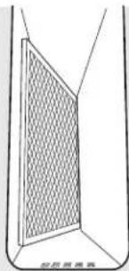
Cuando se encuentre reemplazando el filtro, cerciórese de que descanse, en un ángulo, en los soportes en la abertura de ventilación.
Para limpiar la cámara de ventilación, use agua caliente y enjabonada. Enjuague con agua limpia y seque bien. No use limpiadores abrasivos; dañarán el acabado. Reemplace el filtro después de que lo limpie y lo seque.

Botones de control
Las perillas de control pueden quitarse para limpiarse.
Para limpiar las perillas, cerciórese de que estén en la posición de OFF (Apagado) Hale cada perilla hacia fuera del vástago.
Para limpiar las perillas, colóquelos en un lavaplatos o realice la limpieza con agua y jabón. Enjuague con agua limpia. Asegúrese que los interiores de las perillas estén secos antes de volver a colocarlas.
Cuando reemplace las perillas, revise que estén en la posición de OFF (Apagado) para garantizar la colocación correcta.
Superficies de Acero Inoxidable (en algunos modelos)
No use virutas de acero; éstas dañarán la superficie.
Para limpiar la superficie de acero inoxidable, use agua tibia con jabón o un limpiador o pulidor para acero inoxidable. Siempre limpie la superficie en la dirección del veteado. Siga las instrucciones del limpiador para limpiar la superficie de acero inoxidable.
Para consultar sobre la compra de limpiadores o lustradores de aparatos de acero inoxidable, o para encontrar la ubicación del distribuidor más cercano, llame a nuestro número gratuito:
Centro de partes nacional ....1.800.626.2002
GEAppliances.com
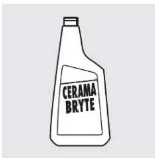
Limpie su estufa después de cada derrame. Use el limpiador de estufas de cerámica CERAMA BRYTE®.
Limpieza de uso normal diario
SOLAMENTE use limpiador de estufas de cerámica CERAMA BRYTE® en su estufa de vidrio. Otras cremas podrían no ser efectivas.
Para mantener y proteger la superficie de su estufa de vidrio, siga estas instrucciones:
1 Antes de usar la estufa por primera vez, limpiela con limpiador de estufas de cerámica CERAMA BRYTE®. Esto ayuda a proteger la parte superior y hace que la limpieza sea más fácil.
2 El uso diario del limpiador de estufas de cerámica CERAMA BRYTE® ayudará a mantener la estufa luciendo como nueva.
3 Remueva la crema de limpieza bien. Aplique unas gotas de limpiador de estufas de cerámica CERAMA BRYTE® directamente sobre la estufa.
4 Use una toalla de papel o una almohadilla de limpiar estufas de cerámica CERAMA BRYTE® para limpiar la superficie entera de la estufa.
5 Use un trapo seco o una toalla de papel para remover los residuos de la limpieza. No necesita enjuagar.
NOTA: Es muy importante que usted NO CALIENTE la estufa hasta que la haya limpiado completamente.

Use una almohadilla de limpiar estufas de cerámica CERAMA BRYTE® o una almohadilla de restregar azul suave multipropósitos Scotch-Brite®.
Residuo quemado encima de la superficie
ADVERTENCIA: DA-O a su superficie de vidrio podría ocurrir si usted usa almohadillas para restregar que no sean las incluidas con su estufa.
1 Permita que la estufa se enfríe.
2 Riegue algunas gotas del limpiador de estufas de cerámica CERAMA BRYTE® en el área entera donde se encuentra el residuo quemado.
3 Usando la almohadilla de limpiar estufas de cerámica CERAMA BRYTE® incluida, restriegue el área de residuo, aplicando presión donde sea necesario.
4 Si cualquier residuo permanece, repita los pasos enumerados anteriormente según sea necesario.
5 Para protección adicional, después de que todo el residuo haya sido removido, pula la superficie entera con la crema limpiadora de estufas de cerámica CERAMA BRYTE® y con una toalla de papel.

El raspador de estufas de cerámica CERAMA BRYTE ® y todos los accesorios recomendados están disponibles a través de nuestro Centro de partes. Ver las instrucciones bajo la sección "Para ordenar partes" en la próxima página.
NOTA: No use una navaja bota o mellada.
Residuo quemado pesado encima de la superficie
1 Permita que la estufa se enfrié.
2 Use un raspador de navaja única a aproximadamente un ángulo de 45° contra la superficie de vidrio y raspe el sucio. Será necesario aplicar presión al raspador para remover el residuo.
3 Después de raspar con el raspador, aplique algunas gotas de limpiador de estufas de cerámica CERAMA BRYTE® en el área entera del residuo quemado. Use la almohadilla de
limpiar estufas de cerámica CERAMA BRYTE® para remover los residuos restantes.
Para protección adicional, después de que todo el residuo haya sido removido, pula la superficie entera con el limpiador de estufas de cerámica CERAMA BRYTE® y con una toalla de papel.
Marcas metálicas y rasguñaduras

Tenga cuidado de no deslizar ollas o sartenes a través de su estufa. Ellas dejarán marcas sobre la superficie de su estufa.
Estas marcas son removibles usando el limpiador de estufas de cerámica CERAMA BRYTE® con la almohadilla de limpiar estufas de cerámica CERAMA BRYTE®.

Si permite que ollas con cubiertas finas de aluminio o de cobre hiervan en seco, la cubierta podría dejar decoloraciones negras sobre la estufa.
Estas deberían removerse inmediatamente antes de calentar la estufa de nuevo o la decoloración se convertirá en decoloraciones permanentes.
ADVERTENCIA: Con mucho cuidado inspeccione el fondo de las sartenes en búsqueda de protuberancias que puedan rasguñar la estufa.
Superficie de vidrio—potencial de daño permanente.
Nuestras pruebas muestran que si usted está cocinando con mezclas de alta concentración de azúcar, tales como jalea o caramelo y ocurre un derrame, puede causar daño permanente a la superficie de vidrio de la estufa a no ser que sea removida inmediatamente.
Daño de derrames de azúcar y plástico derretido

Apague todas las unidades de superficie. Remueva las sartenes calientes.

Usando un guante de hornos:
a. Use un raspador de navaja única (Raspador de estufas de cerámica CERAMA BRYTE®) para remover el derrame a un área fría en la estufa.
b. Remueva el derrame con toallas de papel.

Cualquier resto del derrame debe
dejarse hasta que la estufa se haya enfriado.

No use las unidades de superficie de nuevo hasta que todos los residuos hayan sido completamente removidos.
NOTA: Si ya han ocurrido hendiduras o indentaciones en la superficie de vidrio, el vidrio de la estufa tendrá que ser reemplazado. En este caso, será necesario darle servicio a la estufa.
Para ordenar partes
Para ordenar el limpiador de estufas de cerámica CERAMA BRYTE® y el raspador para estufas, por favor llámenos gratuitamente al número:
Centro de partes nacional 800.626.2002
El limpiador de estufas de cerámica
CERAMA BRYTE® ......# WX10X300
Raspador de estufas de cerámica
CERAMA BRYTE® ....# WX10X0302
Kit ....# WB64X5027 (El Kit incluye la crema y el raspador)
Almohadilla de limpiar estufas de cerámica CERAMA BRYTE®. .#WX10X350
Instrucciones de instalación
Estufa radiante de ventilación descendente
Si tiene alguna pregunta, llame al 800.GE.CARES (800.432.2737) o visite nuestro sitio en la Web: GEAppliances.com
ANTES DE COMENZAR
Lea estas instrucciones completa y cuidadosamente.
- IMPORTANTE – Guarde estas instrucciones para ser usadas por el inspector eléctrico.
- IMPORTANTE – Observe todos los códigos y ordenanzas aplicables.
- Nota al instalador – Cerciórese de dejar estas instrucciones con el Consumidor.
- Nota al consumidor –Guarde estas instrucciones para referencia futura.
- A no ser que usted sea una persona muy bien entrenada en la instalación de este producto, busque la ayuda de un instalador profesional.
- La instalación apropiada es la responsabilidad del instalador.
- Si este producto falla por una instalación inapropiada, la Garantía no cubrirá este producto.
ADVERTENCIA – Antes de comenzar la instalación, desconecte el interruptor de suministro eléctrico en el panel de servicio y cierre el mecanismo de seguridad para evitar que alguien lo conecte accidentalmente. Cuando no exista un dispositivo de cierre de seguridad, amarre un aviso visible, como una etiqueta al panel de servicio haciendo la advertencia.
INSTRUCCIONES IMPORTANTES DE SEGURIDAD
ADVERTENCIA- PARA REDUCIR EL RIESGO DE INCENDIOS, DESCARGAS ELÉCTRICAS O LESIONES PERSONALES, OBSERVE LO SIGUIENTE:
A El trabajo de instalación y el alambrado eléctrico debe hacerlo una persona(s) calificada conforme a todos los códigos y estándares aplicables, incluyendo una construcción aprobada por el inspector de incendios.
B Suficiente aire es necesario para una combustión apropiada y para deshacerse de los gases a través de una salida de humo (chimenea) de equipos que queman combustibles para prevenir retroalimentación. Siga las recomendaciones del fabricante del equipo de calentamiento y los estándares de seguridad tales como los publicados por la Asociación nacional de protección de incendios (NFPA), y la Sociedad americana de ingenieros de calefacción, acondicionadores de aire y refrigeración (ASHRAE), y los códigos de las autoridades locales.
C Cuando se encuentre cortando o taladrando en la pared o en el techo, no dañe los alambrados eléctricos u otras utilidades escondidas.
D Los ventiladores conectados a conductos deben siempre estar ventilados hacia el exterior.
- La unidad debe estar conectada a tierra apropiadamente.
ADVERTENCIA — PARA REDUCIR EL RIESGO DE INCENDIOS, SOLAMENTE USE CONDUCTOS METÁLICOS.
DESEMPACANDO SU ESTUFA
PARTES INCLUIDAS (EMPACADAS DEBAJO DE LA ESTUFA)
- Ensambladura del soplador
- Cámara del soplador
-
Tuercas (4) (10-32 tuercas - con sus arandelas de cierre pegadas)
-
Tornillos de plancha metálica (9) (8-18 x 3/8")
• Cinta de junta de espuma (rollo de 9 pies) -
Rejilla de ventilación
-
Filtro del ventilador
- Crema de limpieza
- Esponja de restriegue o raspador (en algunos modelos)
Asegúrese que todos los materiales de empaque y cintas se hayan retirado. Esto incluye cintas sobre las perillas de control (si corresponde), cinta adhesiva, cintas de ajuste, cartón y plástico protector. Si estos materiales no se retiran se puede producir como resultado un daño sobre el electrodoméstico, una vez que el mismo fue encendido y las superficies se calientan.

Rejilla de ventilación

PRECAUCIÓN:
NO LEVANTE POR LA ABERTURA DE VENTILACIÓN O CHOQUE EL VIDRIO.
Tornillos de plancha metálica (9) (8-18 x 3/8")

Crema de limpieza (WX10X300)
Esponja de restriegue o raspador (en algunos modelos)
Cinta de junta de espuma (rollo de 9 pies)
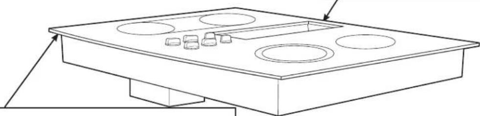
PRECAUCIÓN: EL VIDRIO ES FRÁGIL. NO CHOQUE LA ESQUINAS DEL VIDRIO DURANTE LA INSTALACIÓN.

Ensambladura del soplador y tuercas de montaje (4) (10-32 tuercas—con sus arandelas de cierre pegadas)
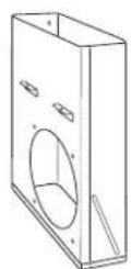
Pleno del
soplador

Filtro del ventilador
PREPARACIÓN
HERRAMIENTAS QUE NECESITARÁ
- Sierra
- Destornillador plano
• Alicates de electricista
• Cinta adhesiva de conductos
• Cinta métrica o escala - Escuadra de carpintero
- Llave de 7/16" o juego de cubos
- Taladradora y broca
- Tornillos para hojas metálicas
- Caja de unión*
- Conducto flexible de 3/4"*
- Cable eléctrico de acuerdo con los códigos locales*
- Tuerca se alambre*
- Conductos
* NOTA: El Kit de instalación eléctrica JXCK89 puede ordenarse por separado e incluye todas las partes necesarias para conectar la estufa a un alambrado típico.

PRECAUCIÓN: PARA SU SEGURIDAD PERSONAL, REMUEVA EL FUSIBLE DE LA CASA O EL INTERRUPTOR DE CIRCUITO ANTES DE COMENZAR LA INSTALACIÓN.
REQUISITOS ELÉCTRICOS
Este electrodoméstico debe suplirse con el voltaje y la frecuencia apropiados, conforme se indica en estas Instrucciones de Instalación, y debe ser conectado a un ramo eléctrico conectado apropiadamente a tierra, protegido por un interruptor de circuito de 40 amperios o fusibles de dilatación de tiempo.
Todas las conexiones de alambres deben hacerse de acuerdo con los códigos locales y deben estar apropiadamente aisladas. Póngase en contacto con la compañía de utilidades local para los códigos eléctricos y ordenanzas de su gobierno. En la ausencia de códigos eléctricos locales, el National Electrical Code, ANSI/NFPA No. 70 – en su más reciente edición, que gobierno la instalación de estufas eléctricas, deben seguirse.
Usted puede obtener una copia del National Electrical Code escribiendo a:
National Fire Protection Association
Batterymarch Park
Quincy, MA 02260
Efectivo el 1 de enero de 1996, el National Electrical Code requiere que las construcciones nuevas, pero no ya existentes, utilicen conexiones de cuatro conductores para estufas eléctricos. Cuando se encuentre instalando una estufa eléctrica en una construcción nueva, siga las instrucciones en CONSTRUCCIÓN NUEVA Y CONEXIÓN DE RAMAL DE CIRCUITO DE CUATRO CONDUCTORES.
Usted debe usar un sistema eléctrico de cables de tres alambres, de fase sencilla AC 208Y/120 voltios o 240/120 voltios, 60 Hertz con conexión a tierra por separado. Si usted conecta a alambres de aluminio, debe usar conectadoras aprobados para el uso con alambrado de aluminio.
ESTUFA DE 30" (DIMENSIONES PARA REFERENCIA SOLAMENTE)
La unidad se muestra totalmente ensamblada.
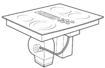


La unidad debe tener ventilación hacia el exterior!
PREPARACIÓN DEL GABINETE
1 PREPARACIÓN PARA LA INSTALACIÓN
Posición de su estufa
La estufa está diseñada para lucir mejor cuando está centrada en un gabinete de por lo menos 30" de ancho.
La ventanilla de escape debajo de la estufa debe estar localizada entre los bajantes de la pared o entre las vigas del piso de forma que el trabajo de tubos pueda ser instalado apropiadamente.
Por lo menos 6" se deben dejar entre los extremos laterales de la estufa y las paredes adyacentes.

Evite colocar gabinetes encima de la unidad, si es posible, para reducir los peligros causados por tener que intentar alcanzar unidades de superficie calentadas. Si los gabinetes están colocados encima de la estufa, los riesgos se pueden reducir instalando una capucha de estufa que proyecte horizontalmente un mínimo de 5 pulgadas más allá del fondo de los gabinetes.
Si se usan gabineterías encima de la estufa, deje una tolerancia mínima de 30" entre la superficie de cocina y el fondo de cualquier gabinete no protegido.
Si la tolerancia entre la estufa y la gabinetería es menor de 30", el gabinete debe protegerse con una plancha retardante de llamas de por lo menos 1/4" de grueso, cubierta con una plancha metálica de acero calibre 28 o con una pancha de cobre de 0.020". La tolerancia entre la estufa y la gabinetería protegida NUNCA DEBE SER MENOR DE 24".
EXCEPCIÓN: La instalación de un horno de microondas especificado o de un electrodoméstico de cocina sobre una estufa debe conformarse a las instrucciones de instalación empacadas con ese electrodoméstico.
15" mínimas deben dejarse a partir de cada lado de extremo de la estufa hasta el fondo de cualquier gabinete no directamente colocado sobre la estufa. Si la tolerancia es menor de 15", los gabinetes adyacentes deben ser de por lo menos 6" desde el lado extremo de la estufa.
2 PREPARACIÓN DEL GABINETE DE LA BASE
Esta estufa está diseñada para ajustar fácilmente en una variedad de gabinetes. Sin embargo, algunos gabinetes podrían requerir modificaciones.
Preparando un gabinete que ajuste contra la pared
En algunos gabinetes, los lados podrían necesitar ser rebajados o cortados 5 3/4 " como se muestra en la figura, y las abrazaderas de las esquinas removidas para acomodar la unidad.
En gabinetes europeos sin forma de 75 cm y 90 cm, el panel posterior podría necesitar ser rebajado hasta 5 3/4 " para acomodar la unidad.
Preparando un gabinete tipo península o tipo isla
En gabinetes tipo península o isla, los lados podrían necesitar ser rebajados o cortados, y las abrazaderas de las esquinas removidas para acomodar la unidad.
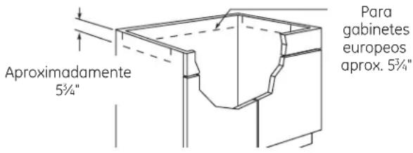
3 PREPARACIÓN RÁPIDA DE UNA CAJA DE UNIÓN
PRECAUCIÓN: PARA SEGURIDAD PERSONAL, REMUEVA EL FUSIBLE DE LA CASA O ABRA EL INTERRUPTOR DE CIRCUITO ANTES DE PREPARAR LA CAJA DE UNIÓN.
Instale una caja de unión aprobada dentro del área sombrada en el diagrama que se muestra en la ilustración. La caja de unión puede estar a por lo menos 10½" del gabinete superior.
Pase los conductores desde el alambrado de la residencia hasta la caja de unión de acuerdo con los códigos eléctricos.

CORTES DE PREPARACIÓN DEL GABINETE
4 PREPARANDO LA ENCIMERA
La encimera debe tener una superficie plana profunda para acomodar la estufa y la ventilación. Las encimeras con un extremo frontal rodado y "backsplash" puede no proporcionar el área de superficie plana requerida.

La tolerancia entre el frente interno del gabinete y la parte posterior del corte en la encimera debe ser de 20 5/8 " para poder acomodar la profundidad de la estufa.

Un área plana de 1/2" de ancho se requiere alrededor del extremo de la abertura para soportar la unidad. La unidad debe ser nivelada y sentarse derecha en la abertura de la encimera.
Con cuidado corte la abertura de la encimera de acuerdo con las dimensiones mostradas en la ilustración. Cerciórese de que la abertura es cortada derecha, con los lados paralelos entre sí y con la parte posterior exactamente perpendicular a los lados.

5 PREPARACIONES PARA LOS CONDUCTOS
NOTA: El trabajo de conductos DEBE tener ventilación hacia el exterior. NO VENTILE hacia las paredes, techo, esquinas, áticos o cualquier otro lugar cerrado.
Corte un agujero en la pared del gabinete o en el piso del gabinete según sea apropiado para su instalación. Cerciórese de que los tubos de escape están localizados entre los bajantes de la pared o las vigas del piso.
NOTA: Cuando se encuentre cortando o taladrando en la pared o en el techo, no dañe los alambrados eléctricos u otras utilidades escondidas.

Ventilación de la pared posterior

Ventilación vertical
6 ALINEACIÓN DE LOS CONDUCTOS DEL SOPLADOR
En general, no instamos al uso de conductos flexibles porque éste puede causar severas restricciones del flujo de aire. Sin embargo, si la salida del soplador y la localización en la pared o en el piso NO representa un problema de alineación, entonces usted puede usar conductos flexibles METÁLICOS para adaptar la compensación. Un buen centramiento sin necesidad de conductos flexibles es lo preferido.
NOTA:
- No exceda la adaptación máxima recomendada de 6".
- No permita que el conducto flexible se doble o que colapse.
- Alargue el conducto flexible tanto como sea posible para evitar la corrugación tanto como sea posible.
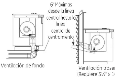
Un rectángulo de 3 1/4 " x 10" a una transición de conducto redondo de 6" está disponible en su tienda de suministros para construcción local.
NOTA: Las ilustraciones son simplemente para que usted planifique.
CÁLCULOS DE LOS CONDUCTOS
| Calcule la longitud de conducto equivalente total | |||
| ==Longitud Número=Longitud Piezas de conducto | equivalente* x =usado == equivalente | ||
| ==Redondos=rectos de 5" | =2,7 Pies = x =(Pies) | t== =Pies | |
| ==Redondos=rectos de 6" | =1 Pies = x =(Pies) | t== =Pies | |
| ==Recto | 3 1/4 " x 10" | 1 Pies x (Pies)l= | =Pies |
| ==Codo de | 5", 90° | 37 Pies x ( ) = | Pies |
| ==Codo de | 6", 90° | 12 Pies x ( ) = | Pies |
| ==Codo de | 5", 45° | 18 Pies x ( ) = | =Pies |
| 6", 45° | 7 Pies x ( ) = | =Pies | |
| Adoptador de encentramiento de metal flexible | 34 Pies x ( ) = | =Pies | |
| ==Codo de 90° | 3 1/4 " x 10" | 14 Pies x ( ) = | Pies |
| ==Codo de 45° | 3 1/4 " x 10" | 8 Pies x ( ) = | Pies |
| Codo plano de 90° 3 1/4 " x 10" | 33 Pies x ( ) = | =Pies | |
| = | Redondos de 5" a transición de 3" x 10" | 3 Pies x ( ) = | Pies |
| Redondos de 5" a transición de 3 1/4 " x 10" | 2 Pies x ( ) = | Pies | |
| === Columna subtotal 1 = Pies | |||
*Las longitudes equivalentes de las piezas de conducto están basadas en pruebas reales y reflejan los requisitos para un buen rendimiento de ventilación con cualquier estufa de flujo de aire descendente.
†Mida y liste los pies de los conductos rectos usados. Cuente y liste la cantidad de todos los otros pedazos de conducto para el “Número usado” de cada tipo.
IMPORTANTE:
Para eficiencia máxima, use la porción de conducto más corta y más recta posible, con la menor cantidad de accesorios posible. Para un rendimiento satisfactorio, el conducto no debe exceder 100 pies de longitud equivalente.
El rendimiento de la ventilación es mejorada usando conductos de mayor diámetro.
| ==Longitud Número=Longitud=Piezas de conducto | equivalente* x usado = | equivalente | ||||
 | Redondo de 5" a transición de 31/4 " x 10" Codo de 90° | 37 Pies | x | ( ) = | Pies | |
| Redondo de 6" a transición de 31/4 " x 10" Codo de 90° | 4 Pies | x | ( ) = | Pies | ||
 | 31/4 " x 10" a transición redonda de 6" | 2 Pies | x | ( ) = | Pies | |
 | 31/4 " x 10" a transición redonda de 6" Codo de 90 | 4 Pies | x | ( ) = | Pies | |
 | Redondo de 5" convergente a transición redonda de 6" | 6 Pies | x | ( ) = | =Pies | |
 | Cuello redondo de 5" a transición redonda de 6" | 13 Pies | x | ( ) = | =Pies | |
 | Tapa redonda de pared de 5" con regulador de tiro | 84 Pies | x | ( ) = | Pies | |
| Tapa redonda de pared de 6" con regulador de tiro | 24 Pies | x | ( ) = | Pies | ||
 | Tapa de pared de 31/4 " x 10" con regulador de tiro | 24 Pies | x | ( ) = | Pies | |
 | Tapa de techo redonda de 6" | 33 Pies | x | ( ) = | Pies | |
| ==Columna subtotal 2 ==Pies | ||||||
| ==Columna subtotal 1 ==Pies | ||||||
| CONDUCTOS TOTALES = | =Pies | |||||
No debe exceder los 100 pies.
Si se utiliza un conducto de ventilación metálico, se deberán duplicar todos los valores en pies equivalentes en la tabla. El conducto metálico flexible deberá ser recto, liso y se deberá extender lo máximo posible.
NO USE conductos de plástico flexibles.
La instalación de la ventilación no debe exceder la longitud equivalente a 100 pies.
RANGOS DEL SOPLADOR DE ESCAPE
ADVERTENCIA DE SEGURIDAD DEL SOPLADOR DE ESCAPE
Suficiente aire es necesario para una combustión apropiada y para deshacerse de los gases a través de una salida de humo (chimenea) de equipos que queman combustibles para prevenir retroalimentación. Siga las recomendaciones del fabricante del equipo de calentamiento y los estándares de seguridad tales como los publicados por la Asociación nacional de protección de incendios (NFPA), y la Sociedad americana de ingenieros de calefacción, acondicionadores de aire y refrigeración (ASHRAE), y los códigos de las autoridades locales.
INSTALACIÓN DE LOS CONDUCTOS
(Nota: Solamente con el propósito de planificación.)
7 CÓMO INSTALAR LOS CONDUCTOS
Use conductos de aluminio o galvanizados en 6" o 3 1/4 " x 10" en tamaño, o una combinación de ambos.
Conductos de PVC se deben usar si se están instalando bajo una capa de concreto vaciado.
NOTA: Los códigos de construcción locales se deben obedecer en especificar el tipo aprobado y la planificación de TODOS los conductos usados.
Siempre use una tapa con regulador de tiro de techo o de pared. Las tapas de pared para electrodomésticos de lavandería no se deben usar NUNCA.

A través del espacio de la base del gabinete

Entre las vigas del piso
Ventilación descendente
Instale el trabajo de conductos, haciendo que la dirección de las conexiones vaya de macho a hembra para el flujo de aire, como se muestra. Asegure todas las juntas con los tornillos para planchas metálicas y con cinta adhesiva de conductos para asegurar la hermeticidad.
Para eficiencia máxima, use la porción de conducto más corta y más recta posible, con la menor cantidad de accesorios posible.

Para un rendimiento satisfactorio, el conducto no debe exceder 100 pies de longitud equivalente. Refiérase al cuadro de los "CÁLCULOS DE LA TUBERÍA" para longitudes equivalentes. Use el cuadro para calcular la longitud equivalente total de los conductos.
INSTALACIÓN OPCIONAL: VENTILACIÓN POR LA PARED POSTERIOR
Para corrientes de CONDUCTO CORTO se puede utilizar el conducto circular de 5 pulgadas pero los mejores resultados se obtendrán con uno de 3,25 pulgadas x 10 pulgadas o con un sistema de conductos circulares de 6 pulgadas.

En el interior de la pared hacia el techo

Directamente
hacia el exterior
Ventilación por la pared posterior
Para convertir la dirección del soplador de escape, remueva las cuatro tuercas detrás del filtro que sostiene el soplador y el protector de alambre.
Rote el soplador y reinstale a la cámara de ventilación, como se muestra encima. Apriete de nuevo las tuercas, pero no las apriete demasiado.
CÓMO DESEMPACAR LA ESTUFA / INSTALAR LA JUNTA
8 CÓMO INSTALAR LA JUNTA DE ESPUMA
No instale la estufa en la encimera sin haber instalado la junta de espuma como se muestra. Esta protege el extremo inferior del vidrio de la encimera y sella la estufa contra derrames.
Remueva la estufa junto a sus almohadillas de empaque de la caja de envío. Remueva el bloque de envío de la abertura de ventilación descendente (downdraft) y colóquela debajo de la almohadilla de envío para proporcionar apoyo de nivel.
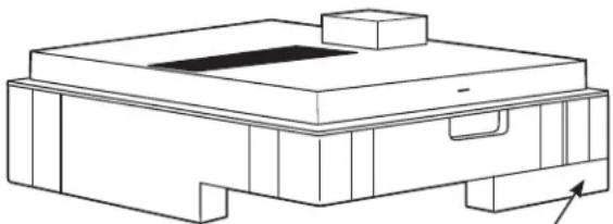
Centre el bloque de envío de la ventilación debajo de la almohadilla de envío para proporcionar apoyo de nivel.
PRECAUCIÓN: EL VIDRIO ES FRÁGIL. NO GOLPEE LOS EXTREMOS DEL VIDRIO DURANTE LA INSTALACIÓN.
Localice la cinta de junta de espuma incluida con su estufa.

Pele la parte posterior blanca para instalar la cinta de la junta de espuma en el lado del fondo del vidrio de la estufa como se muestra.
Nota: En el modelo de acero inoxidable PP989S, aplique la cinta de espuma únicamente alrededor del borde exterior del vidrio en los lados y parte posterior de la unidad.
Notas sobre la instalación de la junta de espuma:
- La cinta de junta de espuma debería ser instalada dentro de 1/8" del extremo del vidrio. No alargue o doble la cinta de junta de espuma.
PRECAUCIÓN: No instalar la cinta de junta de espuma aumenta el potencia de que el vidrio de la estufa se rompa cuando se esté instalando, especialmente en encimeras Corian® o de granito.
- Use cuidado extremo de no alargar la cinta de junta de espuma mientras la instala o no permanecerá en su lugar.
- No coloque la cinta de junta de espuma sobre los bordes metálicos.
- Empalme los extremos de la cinta de junta de espuma en cada esquina sin que una quede encima de la otra.
- Cubra todo el marco con la cinta de junta de espuma sin alargarla.
- Corte las esquinas externas de la cinta de junta de espuma ligeramente si fuera necesario para que luzca bien.
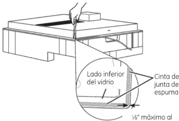
1/8 " máximo al extremo del vidrio
- No rasguñe el vidrio mientras corta la cinta de junta de espuma.
CÓMO INSTALAR LA ESTUFA
9 CÓMO INSTALAR LA ESTUFA

PRECAUCIÓN: NO LEVANTE POR LA ABERTURA DE VENTILACIÓN.
Levante la estufa por los extremos del lado del vidrio como se muestra.
NOTA: No use la abertura de ventilación para levantar o mover la estufa de posición.

Baje la estufa hacia la abertura en la encimera, guiándola hasta llegar a su posición. El vidrio es frágil—no permita que se caiga sobre la encimera. Apoye desde el lado inferior y baja con cuidado.
Cuidadosamente remueva sus dedos de una esquina a la vez para bajar la estufa hasta su posición.
NOTA: No use RTV de silicona o masilla para unir el vidrio de la estufa a la encimera.
10 CÓMO INSPECCIONAR LO PLANO
Inspeccione el vidrio de la estufa en busca de rocas o brechas con protuberancias en todos los lados de la superficie de la encimera. No intente forzar el vidrio a moldearse a la encimera.
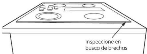
11 CÓMO COLOCAR LOS SOPORTES DE INSTALACIÓN OPCIONALES
NOTA: Verifique que el vidrio esté plano en el paso 9 antes de colocar los soportes de instalación opcionales.

Para solicitar soportes de instalación opcionales/ tornillos de apriete, llame al Centro Nacional de Piezas al 800.626.2002.
Solicite dos de cada pieza: WB02X11331 Soporte WB01X10353 Tornillo
Para colocar soportes de instalación opcionales: Quite los 2 tornillos a ambos lados bajo la estufa. Alinee el soporte de instalación opcional bajo la estufa y reinstale los tornillos a través de la ranura del soporte.
Haga esto en ambos lados de la estufa. Introduzca el tornillo de apriete a través del orificio del soporte y ajuste para fijar la estufa al mostrador de encimera. Repita en el otro lado.
IMPORTANTE: Gire el tornillo de apriete hasta que toque la parte inferior de la estufa. No ajuste de más.
CÓMO INSTALAR LA ESTUFA
12 CÓMO INSTALAR LA CÁMARA DEL SOPLADOR DE LA ESTUFA
Deslice la cámara, con la abertura del soplador del lado izquierdo, en la abertura en el fondo de la estufa. Empuje la cámara hasta que se detenga cuando la cámara haga contacto con el fondo de la estufa, y la cámara encaje en su lugar. (Es posible que usted tenga que mover la cámara hacia adelante y hacia atrás para encontrar su lugar exacto.)

Asegure la cámara al fondo de la estufa, en cada lado, usando los cuatro (4) tornillos proporcionados. Luego asegure la cámara a la estufa, a partir del lado superior, usando los dos (2) tornillos proporcionados.
13 CÓMO INSTALAR LA CÁMARA DEL SOPLADOR
Oriente la abertura de descarga del soplador hasta que iguale el conducto en los Pasos 6 y 7. Deslice las cuatro tachuelas roscadas en el lado del alojamiento del soplador en los cuatro agujeros en el lado de la cámara.
NOTA: Ver el Paso 14 para la instalación del conducto de transición del soplador. Es posible que sea más fácil instalar el conducto de transición al soplador antes de instalar el soplador a la cámara.

A partir de la abertura de ventilación en la parte superior de la estufa, apriete la ensambladura del soplador de manera firme a la cámara con cuatro (4) tuercas.
4 tuercas (se necesita un cubo de tuercas de 7/16")

CÓMO PEGAR UNA TRANSICIÓN DE SOPLADOR
14 CÓMO PEGAR UNA TRANSICIÓN DE SOPLADOR
Use un conducto de transición de soplador para todas las instalaciones de conductos de flujo de aire descendente para conectar las piezas de conducto de 6" redondas. Este conducto rectángulo de 3 1/4 " x 10" a conducto de 6" redondo de transición está disponible en su ferretería local.

Remueva la empaquetadura de cartón en la salida del soplador.
Instale el conducto de transición a la salida del soplador. Asegure toda las juntas con cinta adhesiva de conducto para asegurar hermeticidad.
15 CÓMO CONECTAR LOS CONDUCTOS
Conecte el conducto preparado en los Pasos 5 y 6 al conducto de transición del soplador.
16 CONEXIONES ELÉCTRICAS DEL SOPLADOR
- Afloje los tornillos y remueva y descarte el tirante metálico que cubre el conectador de 5 pasadores. Guarde los tornillos para la reinstalación más tarde.

16 CONEXIONES ELÉCTRICAS DEL SOPLADOR (cont.)
- Conecte el tapón de 5 pasadores en la ensambladura para combinar con el receptáculo de 5 pasadores en el fondo del alojamiento alambrado.

Doble todos los alambres en el alojamiento eléctrico. Asegure el alojamiento con los tornillos removidos anteriormente, cerciorándose de que no quedaron alambres atrapados.

CONEXIONES ELÉCTRICAS
17 ANTES DE HACER CONEXIONES ELÉCTRICAS
Nota al electricista: Los conductores proporcionados con este electrodoméstico son reconocidos por la UL para conexiones eléctricas residenciales de calibres altos. El aislamiento de estos conductores es considerado a temperaturas mucho mayores que las esperadas en residencias. La capacidad de carga actual de un conductor es determinado por el calibre del cable y también por la temperatura considerada del aislamiento alrededor del cable.
Alambre de aluminio - ADVERTENCIA: UNA CONEXIÓN DEL ALAMBRE DE ALUMINIO RESIDENCIAL INAPROPIADA A CONDUCTORES DE COBRE PUEDE RESULTAR EN PROBLEMAS SERIOS.
Una los alambres de aluminio y los alambres de cobre usando conectadores especialmente diseñados y reconocidos por UL para unir cobre y aluminio. Siga el procedimiento recomendado por el fabricante de los conectadores muy de cerca.
Onda de servicio – Deje una onda en el alambre de la estufa de forma tal que la estufa pueda ser levantada 12 pulgadas sin tener que desconectarse del alambrado.
REQUISITOS ELÉCTRICOS*
# Modelo Voltaje Frecuencia KW
PP989 120/240V 60Hz 9.1KW
120/208V 60Hz 6.9KW
* Para referencia solamente. Verifique con la plato de especificación del producto.

Plato de especificación
El Kit de instalación eléctrica JXCK89 puede ordenarse por separado e incluye todas las partes necesarias para conectar la estufa a un alambrado típico.
18 INSTALE UN CONDUCTO FLEXIBLE DE 3/4"
Remueva los tornillos que sostienen la cubierta del compartimiento del alambre y remueva la cubierta.

Alimente los conductores para el suministro eléctrico a través del conducto; cerciórese de dejar suficiente longitud para conectar apropiadamente estos conductores a los conductores eléctricos de la estufa.
Envuelva los conductores a través del bushing o cojinete anti-cortocircuitos y asiente firmemente el bushing en el extremo del conducto.
Alimente los conductores a través del agujero en el compartimiento de alambre.
Conforme lo permitan los códigos locales, compre un conectador de conducto apropiado para el tamaño del conducto. Inserte el conducto a través del conectador y péguelo a la cubierta. Deje un huelgo suficiente para poder pegar los cables fácilmente con los cables de la estufa.
Nota: No Instale la estufa sin un conectador de conducto certificado. El conectador de conducto debería instalarse antes de reinstalar la cubierta de cables.
Cuando haya completado el proceso, reinstale la cubierta del compartimiento de los cables.
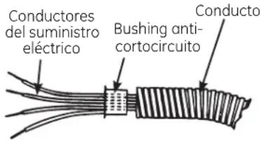
Bushing (asentado completamente)


Conducto Cabierta
CONEXIONES ELÉCTRICAS
19 CÓMO HACER LAS CONEXIONES ELÉCTRICAS
Efectivo el 1 de enero de 1996, el National Electrical Code requiere las construcciones nuevas, pero no ya existentes, utilicen conexiones de cuatro conductores para estufas eléctricos. Cuando se encuentre instalando una estufa eléctrica en una construcción nueva, siga las instrucciones en CONSTRUCCIÓN NUEVA Y CONEXIÓN DE RAMAL DE CIRCUITO DE CUATRO CONDUCTORES.
Usted debe usar un sistema eléctrico de cables de tres alambres, de fase sencilla AC 208Y/120 voltio o 240/120 voltio, 60 Hertz con tierra por separado. Si usted conecta a alambres de aluminio, usted debe usar conectadores aprobados para el uso con alambrado de aluminio.
Construcciones nuevas y conexión de circuito de ramal de cuatro conductores
- Cuando instale una construcción nueva, o
- Cuando instale una casa móvil, o
- Cuando los códigos locales no permitan conexión a tierra a través del neutro:
Circuito de ramal de 4 conductores
Cuando conecte la estufa a un circuito de cuatro conductores o filamentos, conecte los conductores rojos de la estufa y el suministro eléctrico al conductor rojo del ramal del circuito; conecte los conectadores negros entre sí. Conecte el conductor blanco de la estufa al suministro eléctrico y a los conductores neutros del ramal del circuito, los que son blancos o grises. Conecte a tierra la unidad conectando el conductor verde de la estufa a los conductores pelados o verdes del suministro eléctrico y del ramal de circuito (conductores de conexión a tierra).
Circuito de ramal de 4 conductores

19 CÓMO HACER LAS CONEXIONES ELÉCTRICAS (cont.)
Conexión de ramal de circuito de tres conductores
- Cuando se encuentre instalando en una construcción existente construida antes del 1 de enero de 1996, y si así lo permiten los códigos locales:
Conexión de ramal de circuito de 3 conductores
Cuando conecte la estufa a un circuito de 3 conductores, conecte los conductores rojos de la estufa y el suministro eléctrico al conductor rojo del ramal del circuito; conecte los conductores negros entre sí. Conecte los conductores verdes y blancos de la estufa al suministro eléctrico y a los conductores neutros del ramal del circuito eléctrico, que son blancos o grises.
Circuito de ramal de 3 conductores
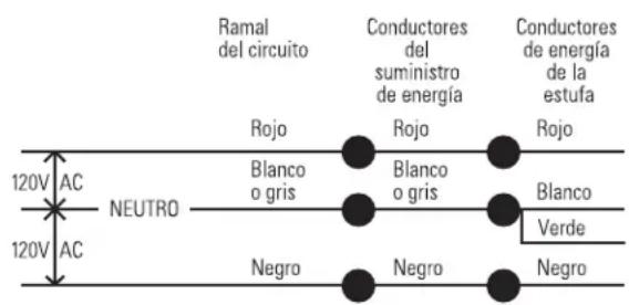
ENSAMBLAJE FINAL

CÓMO INSTALAR EL FILTRO DE FLUJO DOWNDRAFT Y LA PARRILLA DE VENTILACIÓN
No opere la ventilación sin el filtro en su lugar.
- Coloque el filtro diagonalmente a través de la abertura de ventilación.
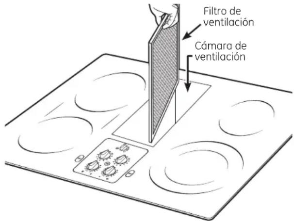
- Cerciórese de que el filtro descanse, en un ángulo, en los soportes de la abertura de ventilación.
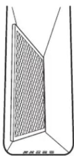
- Cuidadosamente coloque la parrilla de ventilación en la abertura de ventilación de aire descendente (downdraft).
INSPECCIONE LA OPERACIÓN DE VENTILACIÓN DE AIRE DESCENDENTE (DOWNDRAFT)
- Gire el control de velocidad del ventilador de ventilación a la posición HI (Alto), MED (Medio) y LO (Bajo), para cerciorarse de que todas las velocidades operan correctamente.
Antes de llamar para solicitar servicio...
Ideas sobre la identificación y solución de problemas – ¡Ahorre tiempo y dinero! Revise esta tabla primero y es posible que no necesite llamarnos en busca de servicio.
| Problema Causas posibles Qué hacer | ||
| El agua no hierve • Cubra la sartén con una tapa.• Apague el ventilador (Posición OFF) hasta que el agua comience a hervir. | ||
| Las unidades de superficie no se mantienen hirviendo o la cocción es lenta usados. | Instrumentos de cocina inapropiados siendo cocina seleccionada. | Los fondos de las sartenes deberían ser planos, de peso considerable y del mismo diámetro que la superficie de |
| Las unidades de superficie no funcionan apropiadamente se aterrizó.Los controles de la inapropiadamente. | Un fusible en su casa podría haberse volado o el interruptor de circuito• Inspeccione que el control correcto haya sido estufa están colocados seleccionó. | Reemplace el fusible o reajuste el interruptor de circuitos. |
| Rasguños diminutos o marcas de metal (podrían parecer grietas) o abrasiones sobre la superficie de vidrio de la estufa radianteLa sartén se ha deslizado a través de la superficie de la estufa. | Métodos de limpieza incorrectos siendo usados.Sartenes con el fondo áspero están siendo usadas o hubo partículas gruesas (sal o arena) entre la sartén y la superficie de la estufa. | Ver la sección Cómo limpiar el vidrio de la estufa.Cerciórese de que los fondos de las sartenes y que las sartenes mismas estén limpias antes de usar. Use sartenes con fondos suaves. Las rasgaduras diminutas no son removibles pero se convierten en más y más pequeñas al ser limpiadas y al pasar el tiempo. |
| Áreas de decoloración o rayas oscuras en la estufano se limpiaron hasta el siguiente uso.incorrectos de limpieza. | Sartenes inapropiadas siendo usadas.pueden removerse usando la crema de limpieza.Superficies calientes en un modelo con una estufa de color pálido.Derrames de comida queUso de métodos | Las marcas de sartenes de aluminio y de cobre, así como los depósitos minerales del agua y de los alimentos conforme el vidrio se enfría.Lea la sección de Limpieza de la cocina de vidrio.Use los procedimientos de limpieza recomendados. |
| Mezclas de azúcar caliente o plástico se derritió sobre la superficie | La sartén caliente se puso en contacto con estas sustancias. | Consulte la sección Superficie de vidrio—potencial de daño permanente en la sección Cómo limpiar la cubierta de vidrio de la estufa. |
| Picadura (o hendidura) de la cocina derramada o plástico derretido en la cocina. | Mezcla de azúcar caliente• Llame a un técnico calificado para su reemplazo. | |
| La cocina emite un sonido que se puede escuchar | La cocina está bloqueada.• Asegúrese de que el Selector de Control de Bloqueo (Control Lock Selector) esté en UNLOCK (Desbloqueo). | |
| Ciclos entre apagado y encendido en las siendo usadas. los ciclos. | Use solamente piezas de cocina planas para minimizar | |
| La estufa se siente caliente es normal. Use sartenes que sean absolutamente planas. | Sartenes inapropiadas siendo usadas.• La superficie de vidrio de la estufa podría parecer más caliente de lo que usted acostumbra a experimentar. Esto | |
| El botón de control no gira girarse sin empujarse. | Los controles de la estufa están ajustados inapropiadamente.• Cuando el botón está en la posición OFF (apagado), el botón debe empujarse hacia abajo antes de ser girado. Cuando el botón está en cualquier otra posición, puede | |
| Ventilación deficiente cerrada. está obstruida. | Filtro tapado.• Limpie el filtro conforme a las instrucciones. | |
| La casa demasiado una fuente de aire.• Abra una ventana levemente para proporcionar | ||
| La tapa de la pared• Remueva el bloqueo de la tapa de la pared exterior. | ||
| La tapa del regulador de tiro de la pare está• Inspeccione la tapa de la pared exterior del regulador de tiro para movimiento libre u obstrucción. | ||
| atascada. | La longitud del conducto excede el máximo de 100• Reduzca el número de codos para simplificar la trayectoria del conducto. | |
| pies recomendado. | ||
Notas.
Garantía de GE para su estufa de cubierta eléctrico.
Todos los servicios de garantía los proporcionan nuestros Centros de Reparación de Fábrica o nuestros técnicos Customer Care® autorizados. Para concertar una cita de reparación, en línea, visítenos en GEAppliances.com, o llame al 800.GE.CARES (800.432.2737). Cuando llame para solicitar servicio, por favor tenga a mano el número de serie y el número de modelo.
Pegue aquí su recibo. Se requiere facilitar prueba de la fecha de compra original para obtener un servicio bajo la garantía.
| Por el período de: | GE reemplazará: |
| Un añoA partir de la fechade la compra original | Cualquier parte de la estufa a gas que falle debido a defectos en los materialeso en la fabricación. Durante esta garantía limitada de un año, GE también proporcioná, sincosto alguno, toda la mano de obra y los servicios internos para reemplazar partes defectuosas. |
| Cinco añosA partir de la fechade la compra original | Una estufa de vidrio de reemplazo si es que: la ruptura se debe a un golpe térmico; la decoloración; o si el molde se desgasta.Una unidad de superficie radiante si se quema.Durante esta garantía adicional limitada de cuatro años, usted será responsable de cualquier labor o servicio en casa. |
Lo que no está cubierto por GE:
Viajes de servicio a su casa para mostrarle cómo funciona el equipo.
■ Instalación, entrega o mantenimiento inapropriada.
Daño o fallas del producto en caso de abuso, uso inadecuado, modificación, uso para otros propósitos que no sean el adecuado, o uso comercial.
Daño a la estufa de vidrio causado por el uso de limpiadores diferentes a las cremas y almohadillas recomendadas.
Daño a la estufa de vidrio causado por derrames endurecidos de materiales azucarados o por plástico derretido que no sean limpiados conforme a las direcciones en el Manual del propietario.
■ Reemplazo de fusibles de la casa o reajuste del sistema de circuitos.
Daño al producto causado por accidentes, incendios, inundaciones o actos de la naturaleza de fuerza mayor.
Daños incidentales o consecuenciales causados por defectos posibles con este aparato.
■ Daños causados después de la entrega.
- Producto no accesible para facilitar el servicio requerido.
EXCLUSIÓN DE GARANTÍAS IMPLÍCITAS—Su único y exclusivo derecho es la reparación del producto, tal y como se indica en esta Garantía limitada. Cualquier garantía implícita, incluyendo las garantías implícitas de comerciabilidad o adecuación para un fin determinado, están limitadas a un año o el período de tiempo más breve permitido por la ley.
Esta garantía se extiende al comprador original y cualquier comprador posterior de productos comprados para uso residencial dentro des Estados Unidos. Si el producto está situado en un área que no dispone de servicio por parte de un proveedor de servicio autorizado de GE, podría tener que hacerse cargo de los costes de envío o bien podría solicitársele que lleve el producto a una centro de servicio de GE autorizado para realizar la reparación. En Alaska, la garantía excluye el costo de envío o las visitas de servicio a su casa.
Algunos estados no permiten la exclusión o las limitaciones de daños incidentales o consecuenciales. Esta garantía da derechos legales específicos, y usted podría tener otros derechos que variarán de estado a estado. Para saber cuáles son sus derechos legales, consulte a la oficina de asuntos del consumidor local o la oficina del Prucurador (Attorney General) en su localidad.

Página Web de GE Appliances
GEAppliances.com
¿Tiene alguna pregunta sobre su electrodoméstico? ¡Pruebe la página Web de GE Appliances 24 horas al día, cualquier día del año! Para mayor conveniencia y servicio más rápido, ya puede descargar los Manuales de los Propietarios, pedir piezas o incluso hacer una cita en línea para que vengan a realizar una reparación.

Solicite una reparación GEAppliances.com
El servicio de expertos GE está a tan sólo un paso de su puerta. ¡Entre en línea y solicite su reparación cuando le venga bien cualquier día del año! O llame al 800.GE.CARES (800.432.2737) durante horas normales de oficina.
Real Life Design Studio (Estudio de diseño para la vida real) GEAppliances.com
GE apoya el concepto de Diseño Universal—productos, servicios y ambientes que pueden usar gente de todas las edades, tamaños y capacidades. Reconocemos la necesidad de diseñar para una gran gama de habilidades y dificultades físicas y mentales. Para más detalles cobre las aplicaciones de GE Diseño Universal, incluyendo ideas de diseño para la cocina para personas con discapacidades, mire nuestra página Web hoy mismo. Para personas con dificultades auditivas, favor de llamar al 800.TDD.GEAC (800.833.4322).
Garantías ampliadas GEAppliances.com
Compre una garantía ampliada y obtenga detalles sobre descuentos especiales disponibles mientras su garantía está aún activa. Puede comprarla en línea en cualquier momento, o llamar al 800.626.2224 durante horas normales de oficina. GE Consumer Home Services estará aún ahí cuando su garantía termine.

Piezas y accesorios GEAppliances.com
Aquellos individuos con la calificación necesaria para reparar sus propios electrodomésticos pueden pedir que se les manden las piezas o accesorios directamente a sus hogares (aceptamos las tarjetas VISA, MasterCard y Discover). Haga su pedido en línea hoy, 24 horas cada día o llamar por teléfono al 800.626.2002 durante horas normales de oficina.
Las instrucciones descritas en este manual cubren los procedimientos a seguir por cualquier usuario. Cualquier otra reparación debería, por regla general, referirse a personal calificado autorizado. Debe ejercerse precaución ya que las reparaciones incorrectas pueden causar condiciones de funcionamiento inseguras.

Póngase en contacto con nosotros GEAppliances.com
Si no está satisfecho con el servicio que recibe de GE, póngase en contacto con nosotros en nuestra página Web indicando todos los detalles así como su número de teléfono o escribanos a:
General Manager, Customer Relations
GE Appliances, Appliance Park
Louisville, KY 40225
Registre su electrodoméstico GEAppliances.com
¡Registre su nuevo electrodoméstico en línea—cuando usted prefiera! El registrar su producto a tiempo le proporcionará, si surgiera la necesidad, una mejor comunicación y un servicio más rápido bajo los términos de su garantía. También puede enviar su tarjeta de registro pre-impresa que se incluye en el material de embalaje.


- RADIANT DOWNDRAFT COOKTOP
- SAFETY INSTRUCTIONS....2-3
- OPERATING INSTRUCTIONS
- CARE AND CLEANING
- INSTALLATION INSTRUCTIONS
- TROUBLESHOOTING TIPS .....26
- CONSUMER SUPPORT
- OWNER'S MANUAL & INSTALLATION INSTRUCTIONS
- WARNING
- GENERAL SAFETY INSTRUCTIONS
- KEEP FLAMMABLE MATERIALS AWAY FROM THE COOKTOP
- IN THE EVENT OF A FIRE, TAKE THE FOLLOWING STEPS TO PREVENT THE FIRE FROM SPREADING
- RADIANT COOKTOP SAFETY INSTRUCTIONS
- FEATURES OF YOUR COOKTOP
- FEATURE INDEX (FEATURES AND APPEARANCE MAY VARY)
- RADIANT SURFACE UNITS
- ABOUT THE RADIANT SURFACE UNITS
- USING THE SURFACE UNITS
- SELECTING TYPES OF COOKWARE
- FOR GLASS COOKTOP MODELS. (ON NON-INDUCTION MODELS) GEAPPLIANCES.COM
- STAINLESS STEEL
- PORCELAIN ENAMEL ON CAST IRON
- ALUMINUM
- PORCELAIN ENAMEL ON STEEL
- COPPER BOTTOM
- GLASS-CERAMIC
- STONEWARE
- CAST IRON
- FOR BEST RESULTS
- CARE AND CLEANING OF THE COOKTOP
- HOW TO REMOVE PROTECTIVE SHIPPING FILM AND PACKAGING TAPE
- VENT GRILLE
- VENT FILTER AND CHAMBER
- CONTROL KNOBS
- STAINLESS STEEL SURFACES (ON SOME MODELS)
- NORMAL DAILY USE CLEANING
- BURNED-ON RESIDUE
- HEAVY, BURNED-ON RESIDUE
- METAL MARKS AND SCRATCHES
- GLASS SURFACE—POTENTIAL FOR PERMANENT DAMAGE
- DAMAGE FROM SUGARY SPILLS AND MELTED PLASTIC
- TO ORDER PARTS
- BEFORE YOU BEGIN
- IMPORTANT SAFETY INSTRUCTIONS
- UNPACKING YOUR COOKTOP
- PARTS INCLUDED (PACKED BELOW THE COOKTOP)
- PREPARATION
- TOOLS AND MATERIALS YOU WILL NEED
- ELECTRICAL REQUIREMENTS
- CABINET PREPARATION
- 1 PREPARING FOR INSTALLATION
- POSITIONING THE COOKTOP
- ② PREPARING THE BASE CABINET
- PREPARING A CABINET THAT IS AGAINST A WALL
- PREPARING A PENINSULA OR ISLAND-TYPE CABINET
- ③ ROUGH PREPARATION OF JUNCTION BOX
- CABINET PREPARATION CUTOUTS
- 4 PREPARING THE COUNTERTOP
- 5 PREPARING FOR DUCTWORK
- 6 BLOWER TO DUCTWORK ALIGNMENT
- NOTE
- DUCTWORK CALCULATIONS
- EXHAUST BLOWER RATINGS
- EXHAUST BLOWER SAFETY WARNING
- DUCTWORK INSTALLATION
- 7 INSTALLING THE DUCTWORK
- OPTIONAL INSTALLATION: REAR WALL VENTING
- UNPACKING THE COOKTOP/INSTALLING THE GASKET
- 8 INSTALLING THE FOAM GASKET
- CAUTION: GLASS IS FRAGILE. DO NOT BUMP EDGE OF GLASS DURING INSTALLATION
- FOAM GASKET INSTALLATION NOTES
- CAUTION: FAILURE TO INSTALL FOAM GASKET TAPE GREATLY INCREASES THE POTENTIAL OF BREAKING THE COOKTOP GLASS WHEN INSTALLING, ESPECIALLY IN CORIAN® OR GRANITE COUNTERTOPS
- INSTALLING THE COOKTOP
- CAUTION
- 10 CHECKING FOR FLATNESS
- 11 INSTALLING THE OPTIONAL INSTALLATION BRACKETS
- 12 INSTALLING THE BLOWER PLENUM TO THE COOKTOP
- 13 INSTALLING THE BLOWER TO THE PLENUM
- 14 ATTACHING A BLOWER TRANSITION DUCT
- 15 CONNECTING THE DUCTWORK
- 16 BLOWER ELECTRICAL CONNECTIONS
- 16 BLOWER ELECTRICAL CONNECTIONS (CONT.)
- ELECTRICAL CONNECTIONS
- 17 BEFORE MAKING ELECTRICAL CONNECTIONS
- ALUMINUM WIRING - ⚠️WARNING: IMPROPER CONNECTION OF ALUMINUM HOUSE WIRING TO THE COPPER LEADS CAN RESULT IN SERIOUS PROBLEMS
- 18 INSTALL 3/4" FLEXIBLE CONDUIT
- 19 MAKING ELECTRICAL CONNECTIONS
- NEW CONSTRUCTION AND FOUR-CONDUCTOR BRANCH CIRCUIT CONNECTION
- 4-CONDUCTOR BRANCH CIRCUIT
- 19 MAKING ELECTRICAL CONNECTIONS (CONT.)
- THREE-CONDUCTOR BRANCH CIRCUIT CONNECTION
- 3-CONDUCTOR BRANCH CIRCUIT
- FINAL ASSEMBLY
- 20 INSTALL DOWNDRAFT FILTER AND VENT GRILLE
- CHECK OPERATION OF DOWNDRAFT
- BEFORE YOU CALL FOR SERVICE
- NOTES
- GE ELECTRIC COOKTOP WARRANTY
- FOR THE PERIOD OF: GE WILL REPLACE
- ONE YEAR
- FIVE YEARS
- WHAT GE WILL NOT COVER
- GE APPLIANCES WEBSITE
- GEAPPLIANCES.COM
- SCHEDULE SERVICE GEAPPLIANCES.COM
- REAL LIFE DESIGN STUDIO GEAPPLIANCES.COM
- EXTENDED WARRANTIES GEAPPLIANCES.COM
- PARTS AND ACCESSORIES GEAPPLIANCES.COM
- CONTACT US GEAPPLIANCES.COM
- REGISTER YOUR APPLIANCE GEAPPLIANCES.COM
- INSTRUCCIONES DE SEGURIDAD .....2-3
- MANUAL DEL PROPIETARIO E INSTRUCCIONES DE INSTALACIÓN
- INSTRUCCIONES DE OPERACIÓN
- CUIDADO Y LIMPIEZA
- INSTRUCCIONES DE INSTALACIÓN
- IDEAS SOBRE LA IDENTIFICACIÓN
- Y SOLUCIÓN DE AVERÍAS....26,27
- APOYO AL CONSUMIDOR
- INSTRUCCIONES DE SEGURIDAD IMPORTANTES. LEA TODAS LAS INSTRUCCIONES ANTES DE USAR
- ADVERTENCIA
- INSTRUCCIONES GENERALES DE SEGURIDAD
- MANTENGA LOS MATERIALES INFLAMABLES ALEJADOS DE LA ESTUFA
- EN CASO DE INCENDIO, SIGA LOS SIGUIENTES PASOS PARA EVITAR LA PROPAGACIÓN DEL FUEGO
- INSTRUCCIONES DE SEGURIDAD DE LA ESTUFA RADIANTE
- CARACTERÍSTICAS DE SU ESTUFA
- UNIDADES DE SUPERFICIE RADIANTES
- ACERCA DE LAS UNIDADES DE SUPERFICIE RADIANTES
- CÓMO USAR LAS UNIDADES DE SUPERFICIE
- ACERO INOXIDABLE
- ALUMINIO
- FONDO DE COBRE
- ESMALTE DE PORCELANA SOBRE HIERROFUNDIDO
- VIDRIO-CERÁMICA
- ESMALTE DE PORCELANA SOBRE ACERO
- CERÁMICA
- VIDRIO-CERÁMICO
- HIERRO FUNDIDO
- PARA MEJORES RESULTADOS
- CUIDADO Y LIMPIEZA DE LA ESTUFA
- REJILLA DE VENTILACIÓN
- CÁMARA Y FILTRO DE VENTILACIÓN
- BOTONES DE CONTROL
- SUPERFICIES DE ACERO INOXIDABLE (EN ALGUNOS MODELOS)
- LIMPIEZA DE USO NORMAL DIARIO
- RESIDUO QUEMADO ENCIMA DE LA SUPERFICIE
- RESIDUO QUEMADO PESADO ENCIMA DE LA SUPERFICIE
- MARCAS METÁLICAS Y RASGUÑADURAS
- SUPERFICIE DE VIDRIO—POTENCIAL DE DAÑO PERMANENTE
- DAÑO DE DERRAMES DE AZÚCAR Y PLÁSTICO DERRETIDO
- PARA ORDENAR PARTES
- ESTUFA RADIANTE DE VENTILACIÓN DESCENDENTE
- ANTES DE COMENZAR
- INSTRUCCIONES IMPORTANTES DE SEGURIDAD
- DESEMPACANDO SU ESTUFA
- PARTES INCLUIDAS (EMPACADAS DEBAJO DE LA ESTUFA)
- PRECAUCIÓN
- PREPARACIÓN
- HERRAMIENTAS QUE NECESITARÁ
- REQUISITOS ELÉCTRICOS
- PREPARACIÓN DEL GABINETE
- 1 PREPARACIÓN PARA LA INSTALACIÓN
- POSICIÓN DE SU ESTUFA
- 2 PREPARACIÓN DEL GABINETE DE LA BASE
- PREPARANDO UN GABINETE QUE AJUSTE CONTRA LA PARED
- PREPARANDO UN GABINETE TIPO PENÍNSULA O TIPO ISLA
- 3 PREPARACIÓN RÁPIDA DE UNA CAJA DE UNIÓN
- PRECAUCIÓN: PARA SEGURIDAD PERSONAL, REMUEVA EL FUSIBLE DE LA CASA O ABRA EL INTERRUPTOR DE CIRCUITO ANTES DE PREPARAR LA CAJA DE UNIÓN
- CORTES DE PREPARACIÓN DEL GABINETE
- 4 PREPARANDO LA ENCIMERA
- 5 PREPARACIONES PARA LOS CONDUCTOS
- 6 ALINEACIÓN DE LOS CONDUCTOS DEL SOPLADOR
- NOTA
- CÁLCULOS DE LOS CONDUCTOS
- IMPORTANTE
- NO USE CONDUCTOS DE PLÁSTICO FLEXIBLES
- RANGOS DEL SOPLADOR DE ESCAPE
- ADVERTENCIA DE SEGURIDAD DEL SOPLADOR DE ESCAPE
- INSTALACIÓN DE LOS CONDUCTOS
- 7 CÓMO INSTALAR LOS CONDUCTOS
- INSTALACIÓN OPCIONAL: VENTILACIÓN POR LA PARED POSTERIOR
- CÓMO DESEMPACAR LA ESTUFA / INSTALAR LA JUNTA
- 8 CÓMO INSTALAR LA JUNTA DE ESPUMA
- PRECAUCIÓN: EL VIDRIO ES FRÁGIL. NO GOLPEE LOS EXTREMOS DEL VIDRIO DURANTE LA INSTALACIÓN
- NOTAS SOBRE LA INSTALACIÓN DE LA JUNTA DE ESPUMA
- PRECAUCIÓN: NO INSTALAR LA CINTA DE JUNTA DE ESPUMA AUMENTA EL POTENCIA DE QUE EL VIDRIO DE LA ESTUFA SE ROMPA CUANDO SE ESTÉ INSTALANDO, ESPECIALMENTE EN ENCIMERAS CORIAN® O DE GRANITO
- CÓMO INSTALAR LA ESTUFA
- 9 CÓMO INSTALAR LA ESTUFA
- 10 CÓMO INSPECCIONAR LO PLANO
- 11 CÓMO COLOCAR LOS SOPORTES DE INSTALACIÓN OPCIONALES
- 12 CÓMO INSTALAR LA CÁMARA DEL SOPLADOR DE LA ESTUFA
- 13 CÓMO INSTALAR LA CÁMARA DEL SOPLADOR
- CÓMO PEGAR UNA TRANSICIÓN DE SOPLADOR
- 14 CÓMO PEGAR UNA TRANSICIÓN DE SOPLADOR
- 15 CÓMO CONECTAR LOS CONDUCTOS
- 16 CONEXIONES ELÉCTRICAS DEL SOPLADOR
- 16 CONEXIONES ELÉCTRICAS DEL SOPLADOR (CONT.)
- CONEXIONES ELÉCTRICAS
- 17 ANTES DE HACER CONEXIONES ELÉCTRICAS
- 18 INSTALE UN CONDUCTO FLEXIBLE DE 3/4
- 19 CÓMO HACER LAS CONEXIONES ELÉCTRICAS
- CONSTRUCCIONES NUEVAS Y CONEXIÓN DE CIRCUITO DE RAMAL DE CUATRO CONDUCTORES
- CIRCUITO DE RAMAL DE 4 CONDUCTORES
- 19 CÓMO HACER LAS CONEXIONES ELÉCTRICAS (CONT.)
- CONEXIÓN DE RAMAL DE CIRCUITO DE TRES CONDUCTORES
- CONEXIÓN DE RAMAL DE CIRCUITO DE 3 CONDUCTORES
- ENSAMBLAJE FINAL
- CÓMO INSTALAR EL FILTRO DE FLUJO DOWNDRAFT Y LA PARRILLA DE VENTILACIÓN
- INSPECCIONE LA OPERACIÓN DE VENTILACIÓN DE AIRE DESCENDENTE (DOWNDRAFT)
- ANTES DE LLAMAR PARA SOLICITAR SERVICIO
- NOTAS
- GARANTÍA DE GE PARA SU ESTUFA DE CUBIERTA ELÉCTRICO
- LO QUE NO ESTÁ CUBIERTO POR GE
- PÁGINA WEB DE GE APPLIANCES
- SOLICITE UNA REPARACIÓN GEAPPLIANCES.COM
- REAL LIFE DESIGN STUDIO (ESTUDIO DE DISEÑO PARA LA VIDA REAL) GEAPPLIANCES.COM
- GARANTÍAS AMPLIADAS GEAPPLIANCES.COM
- PIEZAS Y ACCESORIOS GEAPPLIANCES.COM
- PÓNGASE EN CONTACTO CON NOSOTROS GEAPPLIANCES.COM
- REGISTRE SU ELECTRODOMÉSTICO GEAPPLIANCES.COM
Marka : GE
Model : Profile PP989TNWW
Kategoria : Piekarnik