
JVM1950SRSS - Mikrofalówka GE - Bezpłatna instrukcja obsługi
Znajdź bezpłatnie instrukcję urządzenia JVM1950SRSS GE w formacie PDF.

| Typ produktu | Mikrofalówka z okapem do montażu nad kuchenką |
| Marka | GE |
| Model | JVM1950SRSS |
| Szerokość | 76,2 cm (30 cali) |
| Głębokość | Maks. 33 cm (13 cali) |
| Wysokość | Ok. 45,7 cm (18 cali) (szacowana) |
| Waga netto | 28,6–38,6 kg (63–85 funtów) |
| Maksymalne obciążenie dodatkowe | Do 22,7 kg (50 funtów) |
| Napięcie zasilania | 120 V AC |
| Częstotliwość | 60 Hz |
| Natężenie prądu | 15 A |
| Moc | 1,7 kW |
| Rodzaj wtyczki | 3-stykowa z uziemieniem |
| Funkcje główne | Ogrzewanie mikrofalowe, wentylacja z odprowadzeniem na zewnątrz (góra/tył) lub recyrkulacja, oświetlenie kuchenki |
| System wentylacji | Wybór: wyprowadzenie górne, tylne lub recyrkulacja (wymaga filtra węglowego) |
| Filtry | Filtry tłuszczu (zmywne), filtr węglowy (opcjonalny do recyrkulacji) |
| Montaż | Do szafki górnej i ściany, wymagane 2 osoby, do 2 uchwytów ściennych (min. 1 w słupku) |
| Bezpieczeństwo | Wtyczka z uziemieniem, wyłącznik obwodu przed instalacją, nie instalować na wyspie ani półwyspie |
| Kraj produkcji | Korea |
| Zgodność z normami | Krajowy Kodeks Elektryczny (USA) |
Często zadawane pytania - JVM1950SRSS GE
Pytania użytkowników dotyczące JVM1950SRSS GE
0 pytanie dotyczące tego urządzenia. Odpowiedz na te, które znasz, lub zadaj własne.
Zadaj nowe pytanie dotyczące tego urządzenia
Pobierz instrukcję dla swojego Mikrofalówka w formacie PDF za darmo! Znajdź swoją instrukcję JVM1950SRSS - GE i weź swoje urządzenie elektroniczne z powrotem w ręce. Na tej stronie opublikowane są wszystkie dokumenty niezbędne do korzystania z urządzenia. JVM1950SRSS marki GE.
INSTRUKCJA OBSŁUGI JVM1950SRSS GE
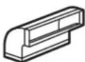
Installation Instructions
Above the Cooktop Oven
JVM1950, JNM1951, DVM1950, PVM1970, PNM1971 and PVM2170
Questions? Call 800.GE.CARES (800.432.2737) or Visit our Website at: GEAppliances.com
BEFORE YOU BEGIN
Read these instructions completely and carefully.
- IMPORTANT – Save these instructions for local inspector's use.
• IMPORTANT— Observe all governing codes and ordinances. -
Note to Installer – Be sure to leave these instructions with the Consumer.
-
Note to Consumer – Keep these instructions for future reference.
- Skill level – Installation of this appliance requires basic mechanical and electrical skills.
• Proper installation is the responsibility of the installer. - Product failure due to improper installation is not covered under the Warranty.

LA SECCIÛN EN ESPAÒOL EMPIEZA EN LA P·GINA 25.
READ CAREFULLY. KEEP THESE INSTRUCTIONS.
CONTENTS
General information
Important Safety Instructions.... 3
Electrical Requirements 3
Hood Exhaust 4,5
Damage - Shipment/Installation 6
Parts Included 6
Tools You Will Need 7
Mounting Space 7
Step-by-step installation guide
Placement of Mounting Plate 8-10
Removing the Mounting Plate 8
Finding the Wall Studs...... 8
Determining Wall Plate Location 9
Aligning the Wall Plate 10
Installation Types 11-22
A Outside Top Exhaust.... 12-14
Attach Mounting Plate to Wall ......12
Preparation of Top Cabinet......13
Assemble and Install Adaptor ....13
Mount the Oven 13, 14
Adjust the Exhaust Adaptor 14
Connecting Ductwork....14
B Outside Back Exhaust.... 15-18
Preparing Rear Wall for
Outside Back Exhaust 15
Attach Mounting Plate to Wall ...... 15, 16
Preparation of Top Cabinet......16
Adapting Blower for Outside
Back Exhaust 16, 17
Mount the Oven 18
C Recirculating.... 19-22
Attach Mounting Plate to Wall .....19
Preparation of Top Cabinet......19
Adapting Blower
for Recirculation 20, 21
Mount the Oven 21, 22
Installing the Charcoal Filter 22
Before You Use Your Oven 23
IMPORTANT SAFETY INSTRUCTIONS
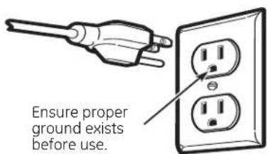
A qualified electrician must perform a ground continuity check on the wall receptacle before beginning the installation to ensure that the outlet box is properly grounded. If not properly grounded, or if the wall receptacle does not meet electrical requirements noted (under ELECTRICAL REQUIREMENTS), a qualified electrician should be employed to correct any deficiencies.

WARNING:
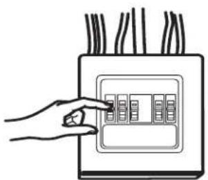
Risk of Electric Shock. Can cause injury or death: Remove house fuse or open circuit breaker before beginning installation to avoid severe or fatal shock injury.
WARNING: Risk of Electric Shock. Can cause injury or death: THIS APPLIANCE MUST BE PROPERLY GROUNDED to avoid severe or fatal shock.
120 V Models

The power cord of this appliance is equipped with a three-prong (grounding) plug which mates with a standard three-prong (grounding) wall receptacle to minimize the possibility of electric shock hazard from this appliance.
Where a standard two-prong wall receptacle is encountered, it must be replaced with a properly grounded three-prong wall receptacle, installed by a qualified electrician.
WARNING: Risk of Electric Shock. Can cause injury or death: DO NOT, under any circumstances, cut, deform or remove any of the prongs from the power cord. Do not use with an extension cord. Failure to comply may cause fire.
ACAUTION: For personal safety, the mounting surface must be capable of supporting the cabinet load, in addition to the added weight of this 63-85 pound product, plus additional oven loads of up to 50 pounds or a total weight of 113-135 pounds.
⚠️CAUTION: For personal safety, this product cannot be installed in cabinet arrangements such as an island or a peninsula. It must be mounted to BOTH a top cabinet AND a wall.
⚠CAUTION: To avoid the risk of personal injury (back injury or other injuries due to excessive weight of the microwave) or property damage, you will need two people to install this microwave.
ELECTRICAL REQUIREMENTS
120 V Models
This product requires a three-prong grounded outlet. Product rating is 120 volts AC, 60 Hertz, 15 amps, and 1.70 kilowatts. This product must be connected to a supply circuit of the proper voltage and frequency. Wire size must conform to the requirements of the National Electrical Code or the prevailing local code for this kilowatt rating. The power supply cord and plug should be brought to a separate 15 to 20 ampere branch circuit single grounded outlet. The outlet box should be located in the cabinet above the oven and away from any potential microwave ducting. The outlet box and supply circuit should be installed by a qualified electrician and conform to the National Electrical Code or the prevailing local code.
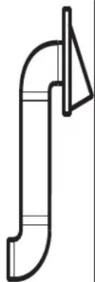
HOOD EXHAUST
NOTE: Read these next two pages only if you plan to vent your exhaust to the outside. If you plan to recirculate the air back into the room, proceed to page 6.
OUTSIDE TOP EXHAUST (EXAMPLE ONLY)
The following chart describes an example of one possible ductwork installation.
| DUCT PIECES = LENGTH =x=USED = == LENGTH | EQUIVALENT = NUMBER = EQUIVALENT | ||
 | =24 Ft. ==x=(1) ====24= | Ft. = | |
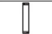 | 12 Ft. Straight Duct(6" Round) | 12 Ft. × (1) = | 12 Ft. |
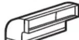
 | =Rectangular-to-RoundAdaptor* | 5 Ft. × (1) = | 5 Ft. |
| Equivalent lengths of duct pieces are based on actual tests andreflect requirements for good venting performance with any vent hood.Total Length = | 41 Ft. | ||
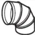
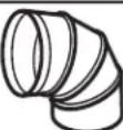
*IMPORTANT: If a rectangular-to-round transition adaptor is used, the bottom corners of the damper will have to be cut to fit, using the tin snips, in order to allow free movement of the damper.
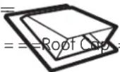
OUTSIDE BACK EXHAUST (EXAMPLE ONLY)
The following chart describes an example of one possible ductwork installation.
| DUCT PIECES | LENGTH* | × | USED | EQUIVALENT = NUMBER = EQUIVALENT LENGTH | |
 | Wall Cap | 40 Ft. | × | (1) | = 40 Ft. |
| 3 Ft. Straight Duct 1/2'' × 103 Rectangular) | 3 Ft. | × | (1) | = 3 Ft. | |
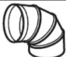 | =90° Elbow | 10 Ft. | × | (2) | = 20 Ft. |
| Equivalent lengths of duct pieces are based on actual tests and reflect requirements for good venting performance with any vent hood.Total Length = 63 Ft. | |||||
NOTE: For back exhaust, care should be taken to align exhaust with space between studs, or wall should be prepared at the time it is constructed by leaving enough space between the wall studs to accommodate exhaust.
NOTE: If you need to install ducts, note that the total duct length of 31/4 " x 10" rectangular or 6" diameter round duct should not exceed 140 equivalent feet.
Outside ventilation requires a HOOD EXHAUST DUCT. Read the following carefully.
NOTE: It is important that venting be installed using the most direct route and with as few elbows as possible. This ensures clear venting of exhaust and helps prevent blockages. Also, make sure dampers swing freely and nothing is blocking the ducts.
Exhaust connection:
The hood exhaust has been designed to mate with a standard 31/4 " × 10" rectangular duct.
If a round duct is required, a rectangular-to-round transition adaptor must be used. Do not use less than a 6" diameter duct.
Maximum duct length:
For satisfactory air movement, the total duct length of 31/4 " x 10" rectangular or 6" diameter round duct should not exceed 140 equivalent feet.
Elbows, transitions, wall and roof caps, etc., present additional resistance to airflow and are equivalent to a section of straight duct which is longer than their actual physical size. When calculating the total duct length, add the equivalent lengths of all transitions and adaptors plus the length of all straight duct sections. The chart below shows you how to calculate total equivalent ductwork length using the approximate feet of equivalent length of some typical ducts.
| DUCT PIECES = ==LENGTH =x=USED===LENGTH | EQUIVALENT ==NUMBER ==EQUIVALENTLENPTH | ||
 | Rectangular-to-Round Adaptor* | 5 Ft. x ( ) = | Ft. |
 | Wall Cap | 40 Ft. x ( ) = | Ft. |
 | 90° Elbow | 10 Ft. x ( ) = | Ft. |
 | 45° Elbow | 5 Ft. x ( ) = | Ft. |
 | 90° Elbow | 25 Ft. x ( ) = | Ft. |
 | 45° Elbow | 5 Ft. x ( ) = | Ft. |
 | Roof Cap | 24 Ft. x ( ) = | Ft. |
| (332X) | Straight Duct 6" Round or 1⁄4" & 10" Rectangular | 1 Ft. x ( ) = | Ft. |
| Total Ductwork = | Ft. | ||

* IMPORTANT: If a rectangular-to-round transition adaptor is used, the bottom corners of the damper will have to be cut to fit, using the tin snips, in order to allow free movement of the damper.
Equivalent lengths of duct pieces are based on actual tests and reflect requirements for good venting performance with any vent hood.
DAMAGE - SHIPMENT/ INSTALLATION
- If the unit is damaged in shipment, return the unit to the store in which it was bought for repair or replacement.
- If the unit is damaged by the customer, repair or replacement is the responsibility of the customer.
- If the unit is damaged by the installer (if other than the customer), repair or replacement must be made by arrangement between customer and installer.
PARTS INCLUDED
HARDWARE PACKET
| PART | QUANTITY | |
 | Wood Screws ( 1/4" × 2" ) | 2 |
 | Toggle Bolts (and wing nuts) ( 1/4" × 3" ) | 2 |
 | Self-aligning Machine Screw ( 1/4" - 28 × 251/6" ) | 2 |
 | Nylon Grommet(for metal cabinets) | 1 |
You will find the installation hardware contained in a packet with the unit. Check to make sure you have all these parts.
NOTE: Some extra parts are included.
PARTS INCLUDED
ADDITIONAL PARTS
| PART | QUANTITY | |
 | ||
 | ||
InstalInstru | ||
Sepal 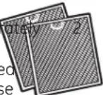 PackeGreasFilters PackeGreasFilters | ||
Exhaus  Dampe Dampe | Adaptor with | 1 |
TOOLS YOU WILL NEED

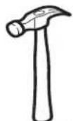
1 and #2 Phillips screwdriver

Pencil
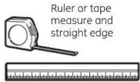
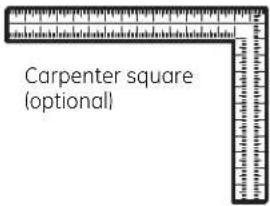
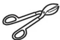
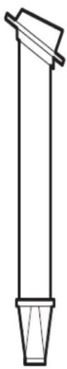
Tin snips (for cutting damper, if required)

Scissors (to cut template, if necessary)
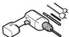
Electric drill with 3/16 ", 7/16 ", 1/2 " and 5/8 " drill bits

Filler blocks or scrap wood pieces, if needed for top cabinet spacing (used on recessed bottom cabinet installations only)

Gloves
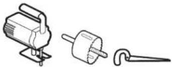
Saw (saber, hole or keyhole)
Stud finder
or
Hammer (optional)
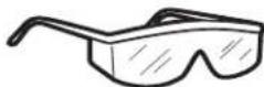
Safety goggles

Level

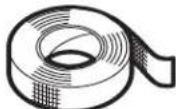
Duct and masking tape
MOUNTING SPACE

NOTES:
- The space between the cabinets must be 30" wide and free of obstructions.
- If the space between the cabinets is greater than 30", a Filler Panel Kit may be used to fill in the gap between the oven and the cabinets. Your Owner's Manual contains the kit number for your model.
- This oven is for installation over ranges up to 36" wide.
- If you are going to vent your oven to the outside, see Hood Exhaust Section for exhaust duct preparation.
- When installing the oven beneath smooth, flat cabinets, be careful to follow the instructions on the top cabinet template for power cord clearance.
- Maximum cabinet depth above and beside the unit is 13".
- For models with top venting holes: Do not allow cabinetry or other objects to block the airflow of the vent.
- The product should not be installed over any cooktop or range with a combined BTU greater than 66,000 BTU.
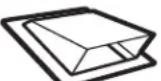
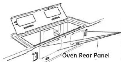
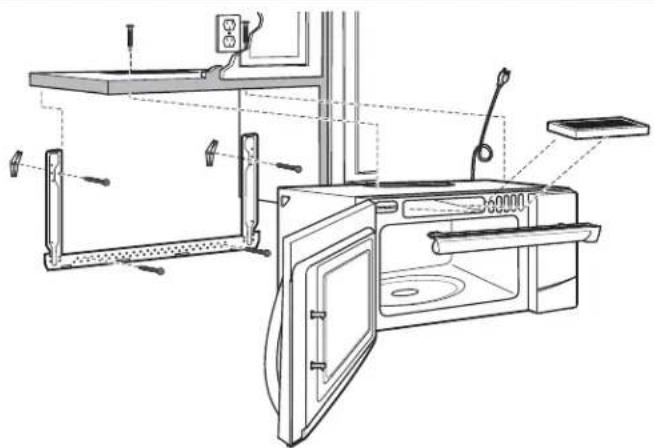
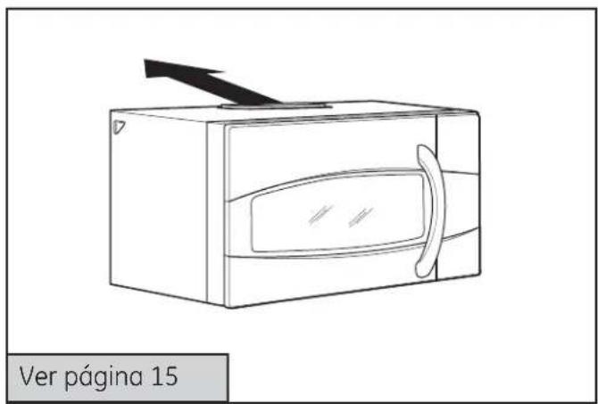
1 | PLACEMENT OF THE MOUNTING PLATE

REMOVING THE OVEN FROM THE CARTON/REMOVING THE MOUNTING PLATE
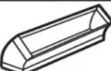
1 Remove the box containing the installation instructions, filters, exhaust adaptor, damper and the small hardware bag. Do not remove the Styrofoam protecting the front of the oven.
2 Fold back all 4 carton flaps fully against carton sides. Then carefully roll the oven and carton over onto the top side. The oven should be resting in the Styrofoam.
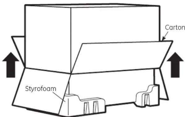
3 Pull the carton up and off the oven.
4 The mounting plate is attached to the back of the oven. Remove the two screws holding it to the oven. The plate will be used as the rear wall template and for mounting the oven to the wall.
5 Set the oven upright. Remove and properly discard plastic bags and Styrofoam.
6 Open the oven door and remove the styrofoam pack from inside the oven. Remove the tape covering the turntable hub.

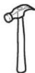
FINDING THE WALL STUDS

1 Find the studs, using one of the following methods:
A. Stud finder - a magnetic device which locates nails.
OR
B. Use a hammer to tap lightly across the mounting surface to find a solid sound. This will indicate a stud location.
2 After locating the stud(s), find the center by probing the wall with a small nail to find the edges of the stud. Then place a mark halfway between the edges. The center of any adjacent studs should be 16" or 24" from this mark.
3 Draw a line down the center of the studs.
IMPORTANT: The microwave must be connected to at least one wall stud.
C DETERMINING WALL PLATE LOCATION UNDER YOUR CABINET
Plate position – beneath flat bottom cabinet
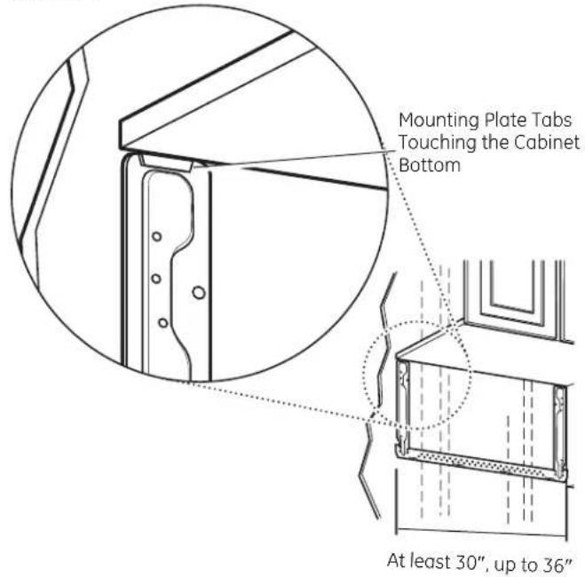
Plate position – beneath framed recessed cabinet bottom

Plate position – beneath recessed bottom cabinet with front overhang

Your cabinets may have decorative trim that interferes with the oven installation. Remove the decorative trim to install the oven properly and to make it level.
THE OVEN MUST BE LEVEL.
Use a level to make sure the cabinet bottom is level.
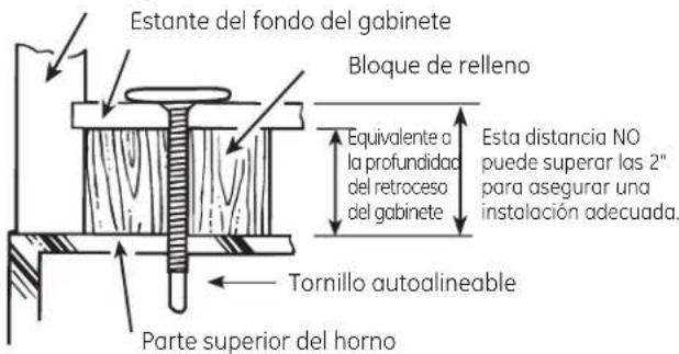
If the cabinets have a front overhang only, with no back or side frame, install the mounting plate down the same distance as the front overhang depth. This will keep the oven level.
1Measure the inside depth of the front overhang.
2 Draw a horizontal line on the back wall an equal distance below the cabinet bottom as the inside depth of the front overhang.
3For this type of installation with front overhang only, align the mounting tabs with this horizontal line, not touching the cabinet bottom as described in Step D.
D ALIGNING THE WALL PLATE
CAUTION:
Wear gloves to avoid cutting fingers on sharp edges.
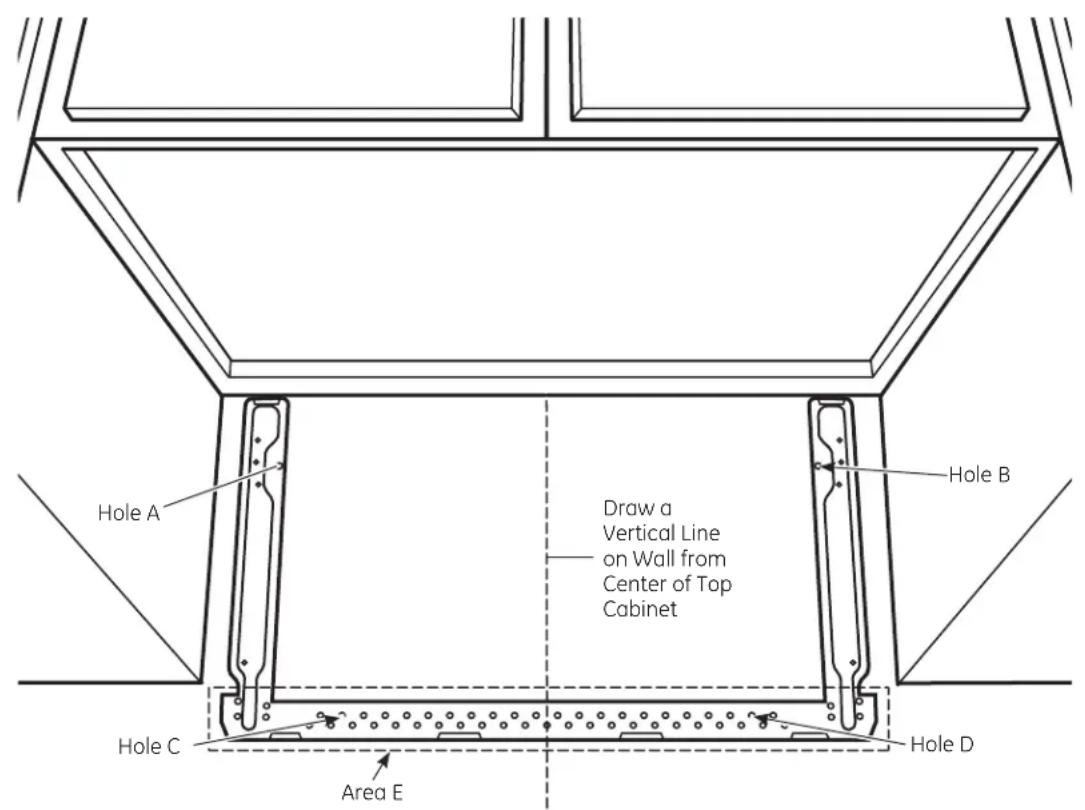
1 Draw a vertical line on the wall at the center of the 30" wide space.
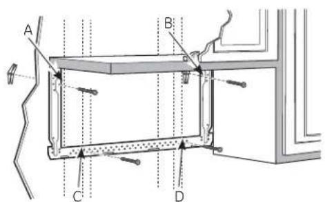
2 Use the mounting plate as the template for the rear wall. Place the mounting plate on the wall, making sure that the tabs are touching the bottom of the cabinet or the level line drawn in Step C for cabinets with front overhang. Line up the notch and center line on the mounting plate to the center line on the wall.
3 While holding the mounting plate with one hand, draw circles on the wall at holes A, B, C and D (see illustration above/actual plate marked with arrows). Four holes must be used for mounting.
NOTE: Holes C and D are inside area E. If neither C nor D is in a stud, find a stud somewhere in area E and draw a fifth circle to line up with the stud. It is important to use at least one wood screw mounted firmly in a stud to support the weight of the oven.
Set the mounting plate aside.
WARNING: Risk of electric shock. Can cause injury or death. Take care to not drill into electrical wiring inside walls or cabinets.
4 Drill holes on the circles. If there is a stud, drill a 3/16 " hole for wood screws. For holes that don't line up with a stud, drill a 5/8 " hole for toggle bolts.
NOTE: DO NOT MOUNT THE PLATE AT THIS TIME.

INSTALLATION TYPES (Choose A, B or C)
This oven is designed for adaptation to the following 3 types of ventilation:
A. Outside Top Exhaust (Vertical Duct)
B. Outside Back Exhaust (Horizontal Duct)
C. Recirculating (Non-Vented Ductless)
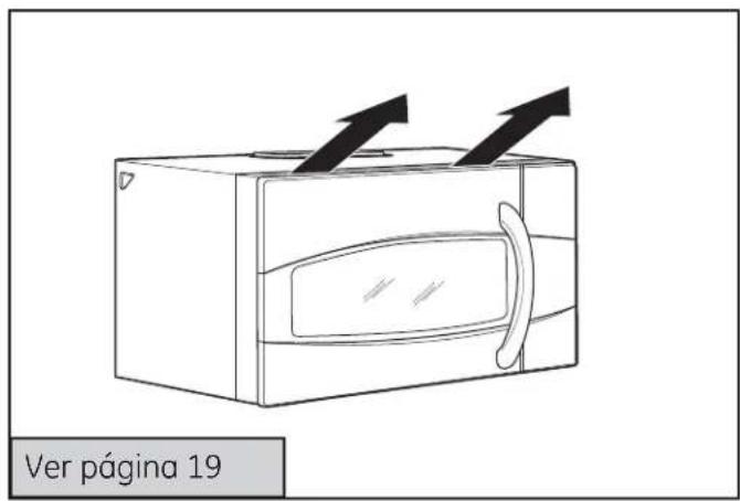
NOTE: For JVM1950, PVM1970, DVM1950, and PVM2170 models. This oven is shipped assembled for Outside Top Exhaust. Select the type of ventilation required for your installation and proceed to that section.
NOTE: For JNM1951 and PNM1971 models. This oven is shipped assembled for Recirculating. Select the type of ventilation required for your installation and proceed to that section.

OUTSIDE TOP EXHAUST (VERTICAL DUCT)


OUTSIDE BACK EXHAUST (HORIZONTAL DUCT)


RECIRCULATING (NON-VENTED DUCTLESS)
A Charcoal Filter Accessory Kit is required for the non-vented exhaust. (See your Owner's Manual for the kit number.)
A OUTSIDE TOP EXHAUST (Vertical Duct)
INSTALLATION OVERVIEW
A1. Attach Mounting Plate to Wall
A2. Prepare Top Cabinet
A3. Install Adaptor
A4. Mount Oven
A5. Adjust Exhaust Adaptor
A6. Connect Ductwork

A1 ATTACH THE MOUNTING PLATE TO THE WALL

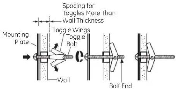
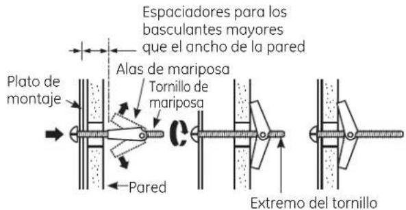
Attach the plate to the wall using toggle bolts. At least one wood screw must be used to attach the plate to a wall stud. Recommended locations on the mounting plate are indicated by A, B, C and D.
1 Remove the toggle wings from the bolts.
2 Insert the bolts into the mounting plate through the holes designated to go into drywall and reattach the toggle wings to 3/4 " onto each bolt.
To use toggle bolts:

3 Place the mounting plate against the wall and insert the toggle wings into the holes in the wall to mount the plate.
NOTE: Before tightening toggle bolts and wood screw, make sure the tabs on the mounting plate touch the bottom of the cabinet when pushed flush against the wall and that the plate is properly centered under the cabinet.
CAUTION: Be careful to avoid pinching fingers between the back of the mounting plate and the wall.
4 Tighten all bolts. Pull the plate away from the wall to help tighten the bolts.
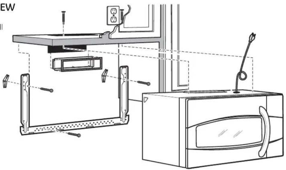
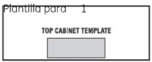
A2 USE TOP CABINET TEMPLATE FOR PREPARATION OF TOP CABINET
You need to drill holes for the top support screws, a hole large enough for the power cord to fit through, and a cutout large enough for the exhaust adaptor.

- Read the instructions on the TOP CABINET TEMPLATE.
- Tape it underneath the top cabinet.
- Drill the holes, following the instructions on the TOP CABINET TEMPLATE.
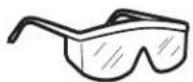
CAUTION: Wear safety goggles when drilling holes in the cabinet bottom.
A3 ASSEMBLE AND INSTALL ADAPTOR
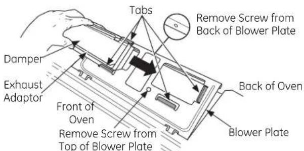
1 Place the oven in its upright position, with the top of the unit facing up and the front of the unit facing toward you.
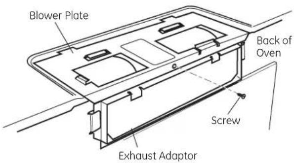
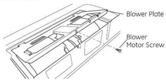
2 Remove the screw on the back side of the blower plate and raise the blower plate off of the microwave.
3 Slide the damper from left to right into the tabs on the blower plate. The yellow tape on the damper should be facing you. If the blower plate is not raised off of the top of the microwave, the damper cannot slide into position.
4 Remove the yellow tape from the damper. Make sure that the damper pivots easily before mounting oven.
You will need to make adjustments to assure proper alignment with your house exhaust duct after the oven is installed.
A4 MOUNT THE OVEN

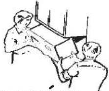
CAUTION: To avoid the risk of personal injury (back injury or other injuries due to excessive weight of the microwave) or property damage, you will need two people to install this microwave.
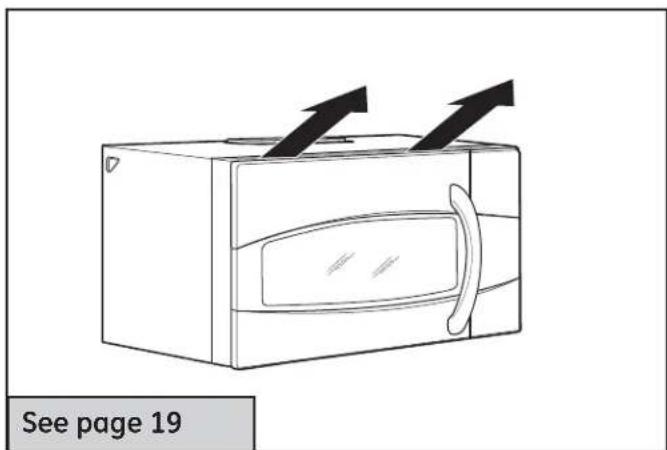
IMPORTANT: Do not grip or use handle during installation.
WARNING: Risk of Electric Shock. Can cause injury or death: If installing unit with metal countertops, cover the edge of the power supply cord hole with the power supply cord bushing.
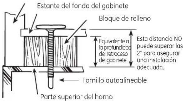
IMPORTANT: If filler blocks are not used, case damage may occur from overtightening screws.
NOTE: When mounting the microwave, thread power cord through hole in bottom of top cabinet. Keep it tight throughout Steps 1-3. Do not pinch cord or lift oven by pulling cord.

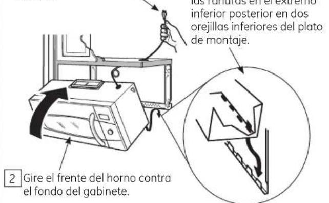
2 Rotate front of oven up against cabinet bottom.
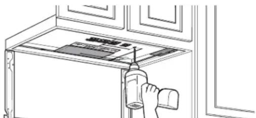
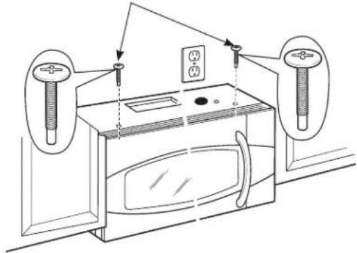
3 Insert a self-aligning screw through top-center cabinet hole. Temporarily secure the oven by turning the screw at least two full turns after the threads have engaged. (It will be completely tightened later.)
A4 MOUNT THE OVEN (continued)
3 Attach the oven to the top cabinet.
4 Insert 2 self-aligning screws ( 1/4 "-28 × 2 5/8 ") through outer top cabinet holes. Turn two full turns on each screw.

Cabinet Front

5 Tighten the outer two screws to the top of the oven. (While tightening screws, hold the oven in place against the wall and the top cabinet.)

6 Install grease filters. See the Owner's Manual packed with the oven.
A5 ADJUST THE EXHAUST ADAPTOR
Open the top cabinet and adjust the exhaust adaptor to connect to the house duct.

A6 CONNECTING DUCTWORK

1 Extend the house duct down to connect to the exhaust adaptor.
2 Seal exhaust duct joints using duct tape.
B OUTSIDE BACK EXHAUST (Horizontal Duct)
INSTALLATION OVERVIEW
B1. Prepare Rear Wall
B2. Attach Mounting Plate to Wall
B3. Prepare Top Cabinet
B4. Adjust Blower
B5. Mount the Oven
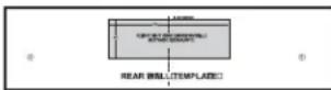
B1 PREPARING THE REAR WALL FOR OUTSIDE BACK EXHAUST
You need to cut an opening in the rear wall for outside exhaust.

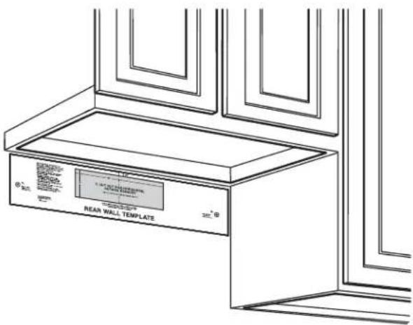
- Read the instructions on the REAR WALL TEMPLATE.
- Tape it to the rear wall, lining up with the holes previously drilled for holes A and B in the wall plate.
- Cut the opening, following the instructions of the REAR WALL TEMPLATE.
B2 ATTACH THE MOUNTING PLATE TO THE WALL

Attach the plate to the wall using toggle bolts. At least one wood screw must be used to attach the plate to a wall stud.
1 Remove the toggle wings from the bolts.
2 Insert the bolts into the mounting plate through the holes designated to go into drywall and reattach the toggle wings to 3/4 " onto each bolt.
To use toggle bolts:

3 Place the mounting plate against the wall and insert the toggle wings into the holes in the wall to mount the plate.
NOTE: Before tightening toggle bolts and wood screw, make sure the tabs on the mounting plate touch the bottom of the cabinet when pushed flush against the wall and that the plate is properly centered under the cabinet.
CAUTION: Be careful to avoid pinching fingers between the back of the mounting and the wall.
4 Tighten all bolts. Pull the plate away from the wall to help tighten the bolts.
B3 USE TOP CABINET TEMPLATE FOR PREPARATION OF TOP CABINET
You need to drill holes for the top support screws and a hole large enough for the power cord to fit through.

- Read the instructions on the TOP CABINET TEMPLATE.
- Tape it underneath the top cabinet.
- Drill the holes, following the instructions on the TOP CABINET TEMPLATE.
A CAUTION: Wear safety goggles when drilling holes in the cabinet bottom.
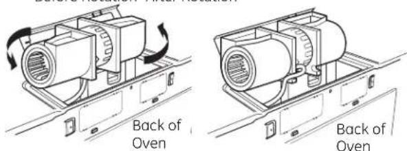
B4 ADAPTING BLOWER FOR OUTSIDE BACK EXHAUST
1 Remove the blower motor screw that holds the blower plate to the oven. Lift the front of the blower plate to install the blower.

2 Carefully pull out the blower unit. The wires will extend far enough to allow you to adjust the blower unit.

3 Rotate blower unit counterclockwise 180°.
Before Rotation After Rotation
4 Gently remove the wires from the grooves. Reroute the wires through grooves on other side of the blower unit.
Before Rerouting After Rerouting

Wires Routed Through Right Side
Wires Routed Through Left Side
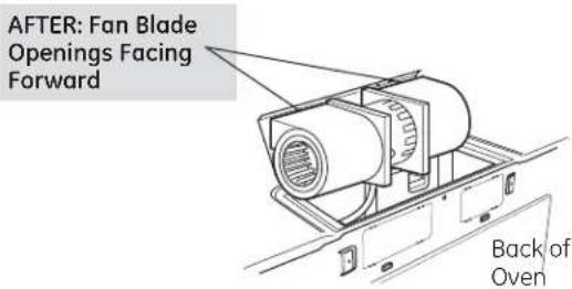
5 Roll the blower unit 90° so that fan blade openings are facing out the back of the oven.

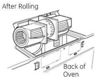
6 Locate the two "knockout" plates, on the rear oven panel, near the top of the oven. Using tin snips, carefully cut the web area from the two holes side-by-side (that secure the knockouts to the oven). Cut all four webs on both rear knockouts; this will allow the ventilation fan airflow to exhaust out the rear of the oven.
BAUTION: Be sure to trim the sharp edges from the openings after removing the knockout plates.
Snip all 4 webs on each knockout panel and remove the metal knockouts for rear airflow.
7 Place the blower unit back into the opening.
AFTER: Fan Blade Openings Facing Back

WARNING: Risk of electric shock can cause injury or death. Do not pull or stretch the blower unit wiring. make sure the wires are not pinched..
NOTE: The blower unit exhaust openings should match exhaust openings on rear of microwave.
8 Attach the exhaust adaptor to the rear of the oven by sliding it into the guides at the top center of the back of the oven.
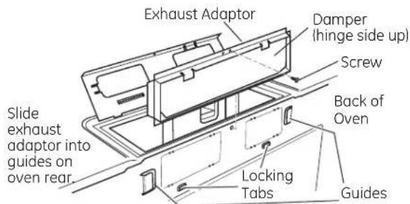
Push down securely until it is in the lower locking tabs. Take care to assure the damper hinge is installed so that it is at the top and that the damper swings freely.
9 Close the blower plate so it is closed over the top tab of the exhaust adapter. Secure with the screw removed earlier.
B5 MOUNT THE OVEN

CAUTION: To avoid the risk of personal injury (back injury or other injuries due to excessive weight of the microwave) or property damage, you will need two people to install this microwave.
IMPORTANT: Do not grip or use handle during installation.
WARNING: Risk of Electric Shock. Can cause injury or death: If installing unit with metal countertops, cover the edge of the power supply cord hole with the power supply cord bushing.
IMPORTANT: If filler blocks are not used, case damage may occur from overtightening screws.
NOTE: When mounting the microwave, thread power cord through hole in bottom of top cabinet. Keep it tight throughout Steps 1-3. Do not pinch cord or lift oven by pulling cord.

2 Rotate front of oven up against cabinet bottom.
3 Insert a self-aligning screw through top-center cabinet hole. Temporarily secure the oven by turning the screw at least two full turns after the threads have engaged. (It will be completely tightened later.)

4 Attach the oven to the top cabinet.
5 Insert 2 self-aligning screws ( 1/4 "-28 x 2 5/8 ") through outer top cabinet holes. Turn two full turns on each screw.

6 Tighten the outer two screws to the top of the oven. (While tightening screws, hold the oven in place against the wall and the top cabinet.)
7 Install grease filters. See the Owner's Manual packed with the oven.

RECIRCULATING (Non-Vented Ductless)
INSTALLATION OVERVIEW
C1. Attach Mounting Plate to Wall
C2. Prepare Top Cabinet
C3. Adjust Blower
C4. Mount the Oven
C5. Install Charcoal Filter (Supplied with
JNM1951, DVM1950 and PNM1971 models)

ATTACH THE MOUNTING PLATE TO THE WALL

Attach the plate to the wall using toggle bolts. At least one wood screw must be used to attach the plate to a wall stud.
1 Remove the toggle wings from the bolts.
2 Insert the bolts into the mounting plate through the holes designated to go into drywall and reattach the toggle wings to 3/4 " onto each bolt.
To use toggle bolts:
3 Place the mounting plate against the wall and insert the toggle wings into the holes in the wall to mount the plate.
NOTE: Before tightening toggle bolts and wood screw, make sure the tabs on the mounting plate touch the bottom of the cabinet when pushed flush against the wall and that the plate is properly centered under the cabinet.
!CAUTION: Be careful to avoid pinching fingers between the back of the mounting plate and the wall.
4 Tighten all bolts. Pull the plate away from the wall to help tighten the bolts.

USE TOP CABINET TEMPLATE FOR PREPARATION OF TOP CABINET
You need to drill holes for the top support screws and a hole large enough for the power cord to fit through.

- Read the instructions on the TOP CABINET TEMPLATE.
- Tape it underneath the top cabinet.
- Drill the holes, following the instructions on the TOP CABINET TEMPLATE.
A CAUTION: Wear safety goggles when drilling holes in the cabinet bottom.
C3 ADAPTING BLOWER FOR RECIRCULATION
NOTE: The exhaust adaptor with damper is not needed for recirculating models. You may want to save them for possible future use.
1 Carefully pull out the blower unit. The wires will extend far enough to allow you to adjust the blower unit.
2 Carefully pull out the blower unit. The wires will extend far enough to allow you to adjust the blower unit.

3 Roll the blower unit 90° so that fan blade openings are facing out the back of the oven.

NOTE: Make sure wires remain routed in the grooves of the motor frame.
4 Place the blower unit back into the opening.
WARNING: Risk of electric shock can cause injury or death. Do not pull or stretch the blower unit wiring. Make sure the wired are not pinched.

5 Close the blower plate. Secure with the screw removed earlier.

C4 MOUNT THE OVEN

CAUTION: To avoid the risk of personal injury (back injury or other injuries due to excessive weight of the microwave) or property damage, you will need two people to install this microwave.
IMPORTANT: Do not grip or use handle during installation.
WARNING: Risk of Electric Shock. Can cause injury or death: If installing unit with metal countertops, cover the edge of the power supply cord hole with the power supply cord bushing.
IMPORTANT: If filler blocks are not used, case damage may occur from overtightening screws.
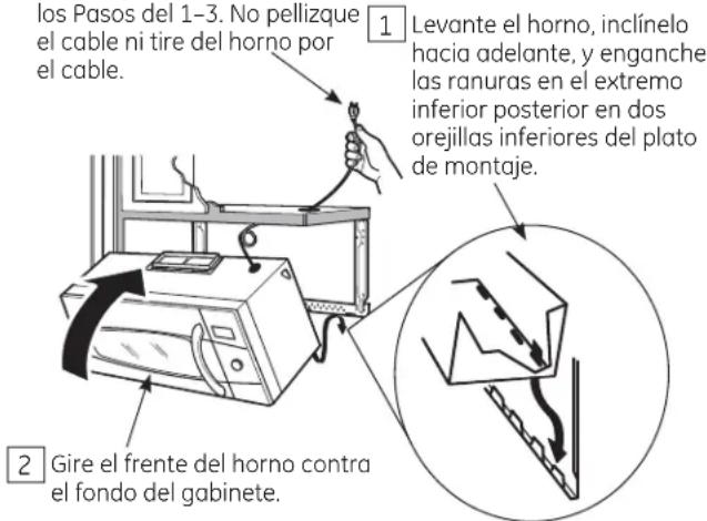
NOTE: When mounting the microwave, thread power cord through hole in bottom of top cabinet. Keep it tight throughout Steps 1–3. Do not pinch cord or lift oven by pulling cord.
1 Lift microwave, tilt it forward, and hook slots at back bottom edge onto four lower tabs of mounting plate.

3 Insert a self-aligning screw through top-center cabinet hole. Temporarily secure the oven by turning the screw at least two full turns after the threads have engaged. (It will be completely tightened later.)

4 Insert 2 self-aligning screws ( 1/4 "-28 x 2 5/8 ") through outer top cabinet holes. Turn two full turns on each screw.

5 Tighten the outer two screws to the top of the oven. (While tightening screws, hold the oven in place against the wall and the top cabinet.)

6 Install grease filters. See the Owner's Manual packed with the oven.
C5 INSTALLING THE CHARCOAL FILTER
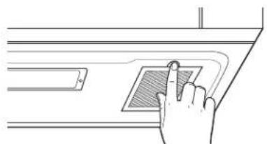
1 Remove 2 screws on top of oven, just above the grille panel, using a Phillips screwdriver.
2 Open the door.
3 Remove the grille. Slide the grille to the left then pull out.

4 Insert the filter into the oven as shown until it fits squarely into place. It will rest at an angle behind the front lower tabs. When properly installed, the wire mesh of the filter should be visible from the front.

5 Replace the grille and the 2 top screws.
6 Close the door and replace left side screw.
BEFORE YOU USE YOUR OVEN
Make sure the oven has been installed according to instructions.

2 Remove all packing material from the oven.
3 Install turntable and wheeled ring in cavity.
4 Replace house fuse or turn breaker back on.
5 120 V Models: Plug power cord into a dedicated 15- to 20-amp electrical outlet.
Where a standard two-prong wall receptacle is encountered, it is very important to have it replaced with a properly grounded three-prong wall receptacle, installed by a qualified electrician.
6 Read the Owner's Manual.

7 KEEP INSTALLATION INSTRUCTIONS FOR THE LOCAL INSPECTOR'S USE.
Printed in Korea
Instrucciones de instalación
Horno para colocar encima de la estufa
JVM1950, JNM1951, DVM1950, PVM1970, PNM1971 y PVM2170
¿Preguntas? Llame 800.GE.CARES (800.432.2737) o visite nuestra página en la red en: GEAppliances.com
ANTES DE EMPEZAR
Lea estas instrucciones completa y cuidadosamente.
- IMPORTANTE – Guarde estas instrucciones para el uso del inspector local.
- IMPORTANTE — Cumpla con todos los códigos y ordenanzas gubernamentales.
-
Nota para el instalador – Asegúrese de dejar estas instrucciones con el consumidor.
-
Nota para el consumidor – Guarde estas instrucciones para futura referencia.
- Nivel de destrezas – La instalación de este aparato requiere de destrezas básicas de mecánica y electricidad.
- La instalación apropiada es responsabilidad del instalador.
- La falla del producto debido a una instalación inapropiada no está cubierta por la garantía.

LEA CUIDADOSAMENTE.
GUARDE ESTAS INSTRUCCIONES.
CONTENIDO
Información general
Instrucciones de seguridad importantes ....3
Requisitos eléctricos 3
Campana de escape 4,5
Daños - Envío / Instalación 6
Partes incluidas 6
Herramientas que necesitará 7
Espacio de montaje 7
Guía de instalación paso por paso
Cómo colocar el plato de montaje 8-10
Cómo remover el plato de montaje 8
Cómo encontrar madera sólida en la pared ....8
Cómo determinar la localización de las placas de la pared .... 9
Cómo alinear la placa de la pared .... 10
Tipos de instalación 11-22
A Escape superior exterior.... 12-14
Cómo adherir la placa de montaje a la pared ....12
Preparación del gabinete superior .....13
Ensamblaje e instalación del adaptador 13
Cómo montar el horno .....13, 14
Cómo ajustar el adaptador de escape ....14
Cómo conectar el conducto 14
B Escape posterior externo 15-18
Cómo preparar la pared posterior para el escape posterior exterior .... 15
Cómo adherir el plato de montaje a la pared .....15, 16
Preparación del gabinete superior .....16
Cómo adaptar el soplador para el escape posterior exterior .....16, 17
Cómo montar el horno 18
Recirculación 19-22
Cómo adherir la placa de montaje a la pared ....19
Preparación del gabinete superior .....19
Cómo adaptar el soplador para la recirculación....20,21
Cómo montar el horno .....21, 22
Cómo instalar el filtro de carbonilla .....22
Antes de comenzar a usar su horno 23
INSTRUCCIONES DE SEGURIDAD IMPORTANTES
Este producto requiere un tomacorriente eléctrico de tres patas conectado a tierra. El instalador debe llevar a cabo una inspección de continuidad a tierra en la caja eléctrica antes de comenzar la instalación para asegurar que la caja tomacorriente está conectada a tierra de manera apropiada. Si no lo está, o si el tomacorriente no cumple con los requisitos eléctricos indicados (bajo la sección REQUISITOS ELÉCTRICOS), se deberá recurrir a un técnico calificado para corregir cualquier deficiencia.

PRECAUCIÓN:
Para seguridad personal, remueva el fusible de la casa o abra el interruptor de circuito antes de comenzar la instalación para evitar descargas eléctricas severas o fatales
ADVERTENCIA: Riesgo de Descarga Eléctrica. Puede ocasionar lesiones o la muerte: ESTE ELECTRODOMÉSTICO SE DEBE CONECTAR A TIERRA DE FORMA CORRECTA a fin de evitar descargas severas o mortales.
Modelos de 120 V

El cable de corriente de este electrodoméstico contiene un enchufe de 3 patas (conexión a tierra) que se conecta a un tomacorriente de pared estándar de 3 cables (conexión a tierra) para minimizar la posibilidad de riesgos de descargas eléctricas por parte del mismo.
Cuando se encuentre un tomacorriente de pared de dos enchufes, se deberá reemplazar por uno de tres cables conectado a tierra de forma adecuada, y deberá ser instalado por un electricista calificado.
ADVERTENCIA: Riesgo de Descarga Eléctrica. Puede ocasionar lesiones o la muerte: NUNCA, bajo ninguna circunstancia, corte, deforme o elimine ninguna de las puntas de los cables de corriente. No use un prolongador. Si no se cumple con esto, se podrán producir incendios.
APRECAUCIÓN: Por razones de seguridad, la superficie de montaje deberá poder soportar la carga del gabinete, sumado al peso agregado de este producto de entre 63 y 85 libras, además de cargas adicionales en el horno de hasta 50 libras o un peso total de entre 113 y 135 libras.
PRECAUCIÓN: Por razones de seguridad, este producto no se puede instalar en arreglos de gabinete tales como una isla o península. Se debe montar TANTO a un gabinete superior COMO a una pared.
A PRECAUCIÓN: A fin de evitar el riesgo de lesión personal (lesión en la espalda u otras lesiones debido a peso excesivo del horno de microondas) o daños sobre el producto, deberá contar con la ayuda de dos personas para instalar este horno de microondas.
REQUISITOS ELÉCTRICOS
Modelos de 120 V
La clasificación del producto es de 120 vatios CA (AC), 60 hertz, 15 amperios, y 1.70 kilovatios. Este producto debe estar conectado a un circuito de suministro del voltaje y frecuencia apropiados. El tamaño del alambre debe conformarse a los requisitos del National Electric Code o al código local en efecto para este índice de kilovatios. El cable eléctrico de alimentación y el interruptor deberán llevarse a un tomacorriente único conectado a tierra de 15 a 20 amperios. La caja del tomacorriente deberá estar localizada en el gabinete encima del horno. La caja del tomacorriente debe ser instalada por un electricista calificado y debe conformarse al National Electrical Code o al código local en efecto.
CAMPANA DE ESCAPE
NOTA: Lea las siguientes dos páginas solamente si planea ventilar el escape hacia el exterior. Si por el contrario planea recircular el aire de vuelta hacia el salón, continúe en la página 30.
ESCAPE SUPERIOR EXTERNO (EJEMPLO SOLAMENTE)
La siguiente tabla describe un ejemplo de una posible instalación de red de conductos.
| PARTES DEL CONDUCTO = =EQUIVALENTE | LONGITUD = =NÚMERO = =LONGITUD= x =USADO = == =EQUIVALENTE | ||
=  | echo = =24 pies = =x =(1) = | ==24 pies = | |
=  | Conducto recto de pies (redondo de 6") | 12 pies × (1) = | |
 | Adaptador de transición de rectángulo a redondo* | 5 pies × (1) = | |
| La longitud de las partes de los conductos equivalentes está basada en pruebas reales y reflejan los requisitos para lograr una buena ventilación con cualquier campana de escape.Longitud total = | 41 pies | ||
*IMPORTANTE: Si se usa un adaptador de transición de rectángulo a redondo, las esquinas del fondo del regulador de tiros deberán cortarse para que encajen, usando las tijeras de corte, para permitir el movimiento libre del regulador de tiros.
ESCAPE POSTERIOR EXTERNO (EJEMPLO SOLAMENTE)
La siguiente tabla describe un ejemplo de una posible instalación de red de conductos.
| PARTES DEL CONDUCTO | EQUIVALENTE | × | USADO | LONGITUD ==N= | ÚMERO ==LONGITUDEQUIVALENTE | ||
 | Tapa de pared | 40 pies | × | (1) | = | 40 pies | |
=  | 3 pies = | Conducto recto de (rectangular de 1⁄4" & 10") | 3 pies | × | (1) | = | 3 pies |
 | Codo de 90° | 10 pies | × | (2) | = | 20 pies | |
| La longitud de las partes de los conductos equivalentes está basada en pruebas reales y reflejan los requisitos para lograr una buena ventilación con cualquier campana de escape. Longitud total = | 63 pies | ||||||
NOTA: Para el escape posterior, se debe tener cuidado al alinear el escape entre los espacios de los postes de viga de la pared, o la pared debería ser preparada en el momento de su construcción dejando suficiente espacio entre los postes de viga de la pared para acomodar el escape.
NOTA: Si usted necesita instalar conductos, tenga pendiente que la longitud total del conducto rectangular de 3 1/4 " x 10" o el conducto redondo de 6" de diámetro no debe sobrepasar 140 pies equivalentes.
La ventilación externa requiere un CONDUCTO DE CAMPANA DE ESCAPE. Lea lo siguiente cuidadosamente.
NOTA: Es importante que la ventilación sea instalada usando la ruta más directa y con la menor cantidad de codos posible. Esto asegura la ventilación del escape y ayuda a prevenir bloqueos. También, cerciórese de que el regulador de tiro pende libremente y nada bloquea los conductos.
Conexiones de escape:
La campana de escape ha sido diseñada para encajar con un conducto rectangular de 3 1/4 " x 10" estándar.
Si un conducto redondo es necesario, se debe usar un adaptador de transición de rectangular a redondo.
No use un conducto menor de 6" de diámetro.
Longitud máxima del conducto:
Para lograr un movimiento satisfactorio del aire, la longitud total del conducto rectangular de 3 ¼" x 10" o el conducto redondo de 6" de diámetro no debe sobrepasar 140 pies equivalentes.
Los codos, transiciones, paredes y tapas de techo, etc., presentan resistencia adicional al flujo de aire y son equivalentes a una sección de conducto recto el cual es más largo que su tamaño físico real. Cuando calcule la longitud total del conducto, agregue las longitudes equivalentes de todas las transiciones y adaptadores, más la longitud de todas las secciones de conducto rectas. La tabla más adelante muestra cómo puede calcular la longitud aproximada de la red de conductos usando pies aproximados de longitudes equivalentes de algunos conductos típicos.
| PARTES DE CONDUCTO = ==EQUIVALENTE | LONGITUD ==NÚMERO ==LONGITUD=x=USADO ==EQUIVALENTE | ||
 = [6000] = [6000] | Adaptador de transición de a redondo* | 5 pies x ( ) = | pies |
 | Tapa de pared | 40 pies x ( ) = | pies |
 | Codo de 90° | 10 pies x ( ) = | pies |
 | Codo de 45° | 5 pies x ( ) = | pies |
 | Codo de 90° | 25 pies x ( ) = | pies |
 | Codo de 45° | 5 pies x ( ) = | pies |
 | Tapa de techo | 24 pies x ( ) = | pies |
| ===o [VDR7] tangular | Conducto recto de 6" redondo 1/4" × 10" | 1 pies ==x ( ) == ==pies | |
| Reed de conductos Total = | pies | ||

* IMPORTANTE: Si se usa un adaptador de transición de rectángulo a redondo, las esquinas del fondo del regulador de tiros deberán ser cortadas para que encajen, usando las tijeras de corte, para permitir el movimiento libre del regulador de tiros.
La longitud de las partes de conductos equivalentes está basada en pruebas reales y reflejan los requisitos para lograr una buena ventilación con cualquier campana de escape.
DAÑOS - ENVÍO / INSTALACIÓN
- Si la unidad se daña durante el envío, devuelva la unidad al almacén donde la adquirió para su reparación o reemplazo.
- Si el cliente daña la unidad, la reparación o el reemplazo es responsabilidad del cliente.
- Si el instalador daña la unidad (si no es el cliente), la reparación o reemplazo se debe hacer por medio de un arreglo entre el cliente y el instalador.
PARTES INCLUIDAS
PAQUETE DE ELEMENTOS
| PARTE CANTIDAD | ||
| Tornillos de madera 2 ( 1/4'' × 2'' ) | ||
1  | vasculantes 2(y tuercas de mariposa) ( 1/4'' × 3'' ) | |
| Tornillos de máquinaautolineables | ( 1/4'' - 28 × 251/8'' ) | 2 |
 | 1 | |
Usted encontrará los elementos de instalación en un paquete junto con la unidad. Inspeccione para cerciorarse de que tiene todas las partes.
NOTA: Se incluyen algunas partes adicionales.
PARTES INCLUIDAS
PARTES ADICIONALES
| PARTE | CANTIDAD | |
 | el gabinete superior | |
 | Plantilla para la pared posterior | 1 |
 | Instrucciones de instalación | 1 |
 | Filtros de grasa empacados por separado | 2 |
 | Adaptador del escape & Regulador de tiro | 1 |
HERRAMIENTAS QUE NECESITARÁ
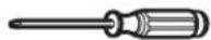
Destornilladores de estrella # 1 y # 2
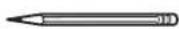
Lápiz


Tijeras para cortar latón (para cortar el regulador de tiro, si es necesario)
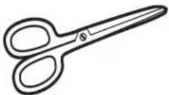
Tijeras (para cortar la plantilla, si es necesario)

Taladro eléctrico con brocas de 3/16 ", 7/16 ", 2/2 " y 5/8 "
Bloques de relleno o pedazos de madera, si son necesarios para rellenar el gabinete (usados solamente en la instalación de gabinetes apoyados)

Guantes

Sierra (de sable, agujero, o de ojo de cerradura)

Detector de postes de viga o
un martillo (opcional)
Gafas de seguridad

Nivel
Cinta de conductos o cinta adhesiva protectora
ESPACIO DE MONTAJE

El extremo del fondo del gabinete necesita estar a 30" o más a partir de la superficie de la estufa
NOTAS:
- El espacio entre los gabinetes debe ser de 30" de ancho y debe estar libre de obstrucciones.
- Si el espacio entre los gabinetes es mayor de 30", un "Filler Panel Kit" podría ser necesario para rellenar las brechas entre el horno y los gabinetes. Su Manual del Propietario contiene el número de kit para su modelo.
- Este horno es para ser instalado por encima de estufas hasta 36" de ancho.
- Si usted se dispone a ventilar su horno hacia el exterior, ver la Sección de Campana de Escape para la preparación del conducto de escape.
- Cuando se instale el horno debajo de gabinetes de fondos lisos y planos, tenga cuidado de seguir cuidadosamente las instrucciones en la plantilla del gabinete superior para el espacio de tolerancia del cable eléctrico.
- La profundidad del gabinete por encima y al costado de la unidad es de 13".
- Para modelos con hoyos de ventilación superiores: No permita que el gabinete u otros objetos bloqueen el flujo de aire de la ventilación.
- El producto no debe instalarse sobre ninguna estufa o cocina con una combinación superior a 66,000 BTU.
1 CÓMO COLOCAR EL PLATO DE MONTAJE
A CÓMO REMOVER EL HORNO DEL EMBALAJE / CÓMO REMOVER EL PLATO DE MONTAJE
1 Remueva la caja que contiene las instrucciones de instalación, los filtros, el adaptador de escape, el regulador de tiro y la pequeña bolsa con los elementos de instalación. No remueva la espuma de poliestireno que protege el frente del horno.
2 Pliegue hacia atrás las alas de la caja. Luego, cuidadosamente ruede el horno hasta que quede apoyado sobre la parte superior. El horno deberá descansar sobre la espuma de poliestireno.

3 Tire de la caja hacia arriba y retírela del horno.
4 El plato de montaje está pegado a la parte posterior del horno. Remueva los dos tornillos que lo sostienen pegado al horno. El plato será usado como la plantilla de la pared posterior y para montar el horno a la pared.
5 Pare el horno. Remueva y descarte de manera apropiada las bolsas plásticas y el poliestireno.
6 Abra la puerta del horno y remueva el paquete de espuma de poliestireno del interior. Remueva la cinta adhesiva que cubre el aro giratorio.
B CÓMO ENCONTRAR LOS POSTES DE VIGA EN LA PARED

1 Encuentre los postes, usando uno de los métodos siguientes:
A. Use un detector de postes - un dispositivo magnético que localiza clavos.
O
B. Use un martillo para golpear ligeramente a través de la superficie de montaje hasta encontrar un sonido sólido. Esto indicará que hay un poste de viga en ese lugar.
2 Después de localizar el poste o los postes de viga, encuentre el centro mediante el análisis de la pared usando un clavo pequeño para darse cuenta de dónde están los bordes del poste. Luego coloque una marca en el centro de los bordes. El centro de cualquier poste adyacente deberá ser entre 16" ó 24" desde esta marca.
3 Trace una línea hacia abajo indicando el centro del poste.
IMPORTANTE: El horno de microondas se deberá conectar a por lo menos un montaje de pared.
CÓMO DETERMINAR LA LOCALIZACIÓN DEL PLATO DE MONTAJE DEBAJO DE SU GABINETE
Posición del plato – debajo de gabinetes de fondo plano

Posición del plato – debajo de gabinetes de fondo apoyado en un marco

Posición del plato - debajo de gabinetes de fondo apoyado con frente saliente

Sus gabinetes podrían tener marcos de decoración que interfieran con la instalación del horno. Remueva los marcos decorativos para instalar el horno apropiadamente y para hacer que quede nivelado.
EL HORNO DEBE QUEDAR NIVELADO.
Use un nivel para cerciorarse de que el fondo del gabinete está nivelado.
Si los gabinetes tienen un saliente frontal solamente, sin marco posterior o lateral, instale el plato de montaje a la misma distancia de la profundidad del saliente. Este mantendrá el horno nivelado.
1Mida la profundidad interna del frente del saliente.
27ace una línea horizontal en la pared posterior a una distancia debajo del fondo del gabinete igual a la profundidad interna del frente saliente.
3P para este tipo de instalación con saliente frontal solamente, alinee las orejillas de montaje con la línea horizontal, sin tocar el fondo del gabinete como se describió en el Paso D.
D CÓMO ALINEAR EL PLATO DE MONTAJE SOBRE LA PARED

PRECAUCIÓN:
Use guantes de protección para evitar cortaduras en sus dedos con los extremos filosos.
1 Trace una línea vertical en la pared en el centro del espacio de 30" de ancho.
2 Use el plato de montaje como la plantilla para la pared posterior. Coloque el plato de montaje en la pared, cerciorándose de que las orejillas se encuentran tocando el fondo del gabinete o la línea marcada en el Paso C para los gabinetes con salientes frontales. Alinee la muesca y línea del centro en el plato de montaje con la línea de centro en la pared.
3 Mientras sostiene el plato de montaje con una mano, trace círculos en la pared en los agujeros A, B, C y D (ver la ilustración anterior / la placa real está marcada con flechas). Deben usarse cuatro agujeros para el montaje.
NOTA: Los agujeros C y D van en el interior del área E. Si ni el C ni el D están en un poste de viga, encuentre un poste en algún otro lugar en el área E y marque un quinto círculo para alinearse con el poste. Es importante usar por lo menos un tornillo de madera montado firmemente en un poste para apoyar el peso del horno.
Aparte el plato de montaje.
ADVERTENCIA: Riesgo de descarga eléctrica. Puede provocar lesiones o la muerte. Tenga cuidado de no perforar el cableado eléctrico ubicado dentro de las paredes o gabinetes.
4 Perfore agujeros en los círculos. Si hay un poste de viga, perfore un agujero de 3/16" para los tornillos de madera. Para los agujeros que no quedaron alineados con el poste de viga, perfore un agujero de 5/8" para los tornillos basculantes.
NOTA: TODAVÍA NO MONTE EL PLATO.
2 TIPOS DE INSTALACIÓN (Escoja A, B o C)
Este horno está diseñado para adaptarse a los siguientes tres tipos de ventilación:
A. Escape Superior Exterior (Conducto vertical)
B. Escape Posterior Exterior (Conducto horizontal)
C. Recirculación (Sin conducto de ventilación)
NOTE: Para modelos JVM1950, PVM1970, DVM1950, y PVM2170. Este horno es enviado ya ensamblado para un Escape Superior Exterior. Seleccione el tipo de ventilación requerido para su instalación y proceda a tal sección.
NOTA: Para modelos JNM1951 y PNM1971. Este horno es enviado ya ensamblado para un Recirculación. Seleccione el tipo de ventilación requerido para su instalación y proceda a tal sección.
A ESCAPE SUPERIOR EXTERIOR (CONDUCTO VERTICAL)

B ESCAPE POSTERIOR EXTERIOR (CONDUCTO HORIZONTAL)
C RECIRCULACIÓN (SIN CONDUCTO DE VENTILACIÓN)
Un Kit de accesorios de filtro de carbonilla es necesario para el sistema sin ventilación. (Consulte su Manual del Propietario para obtener el número del kit.)
A | ESCAPE SUPERIOR EXTERIOR (Conducto vertical)
PERSPECTIVA GENERAL DE LA INSTALACIÓN
A1. Como adherir el plato de montaje a la pared
A2. Prepare el gabinete superior
A3. Instale el adaptador
A4. Monte el horno
A5. Ajuste el adaptador de escape
A6. Conecte el conducto

A1 CÓMO ADHERIR LA PLACA DE MONTAJE A LA PARED
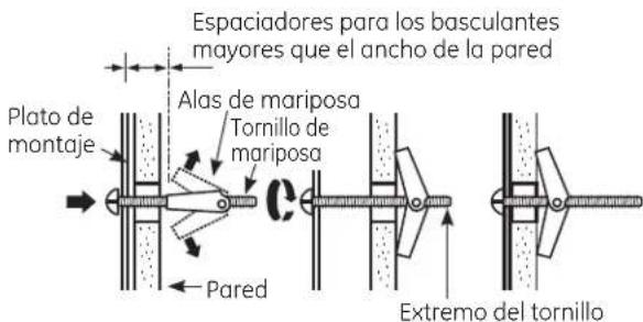
Pegue el plato a la pared usando los tornillos basculantes. Por lo menos un tornillo de madera debe ser usado para pegar el plato al poste de la pared. Las ubicaciones recomendadas sobre la placa de montaje se indican en A, B, C y D.
1 Remueva las mariposas del basculante de los tornillos.
2 Inserte los tornillos en el plato de montaje a través de los agujeros diseñados para ser insertados en la pared de mampostería seca y pegue otra vez las mariposas de 3/4 " en cada tornillo.
Para usar los tornillos basculantes:
3 Coloque el plato de montaje contra la pared e inserte las alas de mariposa en los agujeros de la pared para montar el plato.
NOTA: Antes de apretar los tornillos basculantes y los tornillos de madera, cerciórese de que las orejillas en el plato de montaje toquen el fondo del gabinete cuando son empujadas contra la pared y de que el plato esté centrado apropiadamente debajo del gabinete.
PRECAUCIÓN: Tenga cuidado de evitar pellizar sus dedos entre la parte posterior del plato de montaje y la pared.
4 Apriete todos los tornillos. Tire del plato en dirección opuesta a la pared para ayudar a apretar los tornillos.
A2 USE LA PLANTILLA DEL GABINETE SUPERIOR PARA LA PREPARACIÓN DEL GABINETE SUPERIOR
Deberá perforar agujeros para los tornillos de apoyo superiores, un agujero suficientemente grande para que el cable eléctrico quepa, y un recorte lo suficientemente grande como para que el adaptador de escape pueda ser introducido.
- Lea las instrucciones sobre la PLANTILLA DEL GABINETE SUPERIOR.
- Péguelo debajo del gabinete superior.
- Taladre los agujeros, siguiendo las instrucciones en la PLANTILLA DEL GABINETE SUPERIOR.
PRECAUCIÓN: Use gafas de seguridad cuando perfore los agujeros en el fondo del gabinete.
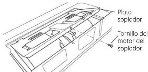
A3 ENSAMBLAJE E INSTALACIÓN DEL ADAPTADOR
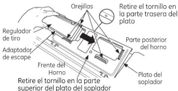
1 Coloque el horno en su posición vertical, con la parte superior de la unidad hacia arriba y el frente hacia usted.
2 Retire el tornillo en la parte trasera del plato soplador y retire el mismo del horno microondas.
Deslice el regulador de izquierda a derecha sobre las lengüetas en el plato soplador. La cinta amarilla del regulador deberá estar de frente hacia usted. Si el plato soplador no se retira de la parte superior del horno microondas, el regulador no se puede deslizar hasta la posición.
Remove the yellow tape from the damper. Cerciórese de que el regulador de tiro gira fácilmente antes de montar el horno.
Deberá hacer ajustes para asegurarse de que existe alineación apropiada con el sistema de conductos de su casa después de la instalación del horno.
A4 CÓMO MONTAR EL HORNO

APRECAUCIÓN: A fin de evitar el riesgo de lesión personal (lesión en la espalda u otras lesiones debido a peso excesivo del horno de microondas) o daños sobre el producto, deberá contar con la ayuda de dos personas para instalar este horno de microondas.
IMPORTANTE: No tome ni use la manija durante la instalación.
ADVERTENCIA: Riesgo de
Descarga Eléctrica. Puede ocasionar lesiones o la muerte: si instala la unidad con encimeros de metal, cubra el agujero del extremo del cable de suministro de corriente con aislante para el cable del suministro de corriente.
IMPORTANTE: Si no se usan bloqueadores de filtro, se podrán producir daños en la caja debido al ajuste excesivo de los tornillos.
NOTA: Cuando se encuentre montando el horno, enrosque el cable eléctrico a través del agujero en el fondo del gabinete superior. Manténgalo tenso a través de los Pasos del 1-3. No pellizque el cable ni tire del horno por el cable.
3 Inserte un tornillo de autoalineación a través del agujero central superior del gabinete. Asegure el horno temporalmente girando el tornillo por lo menos dos vueltas completas después de que las roscas hayan agarrado. (Luego quedarán totalmente apretadas).
A4 CÓMO MONTAR EL HORNO (continuación)
3 Pegue el horno a la parte superior del gabinete.
4 Inserte 2 tornillos (¼"-28 × 2 5/8") autoalineables a través de los agujeros exteriores superiores del horno. Gire dos vueltas completas en cada tornillo.
Frente del gabinete

5 Apriete los dos tornillos exteriores hacia la parte de arriba del horno. (Mientras aprieta los tornillos, mantenga el horno en su lugar contra la pared y el gabinete superior.)

6 Instale los filtros de grasa. Ver el Manual del Propietario que viene con el horno.
A5 CÓMO AJUSTAR EL ADAPTADOR DE ESCAPE
Abra el gabinete superior y ajuste el adaptador de escape para conectarlo al conducto de la casa.

A6 | CÓMO CONECTAR EL CONDUCTO

1 Extienda el conducto de la casa hacia abajo para conectarlo con el adaptador de escape.
2 Selle las juntas del conducto de escape usando cinta adhesiva de conductos.
B ESCAPE POSTERIOR EXTERNO (Conducto horizontal)
PERSPECTIVA GENERAL DE LA INSTALACIÓN
B1. Prepare la pared posterior
B2. Pegue el plato de montaje a la pared
B3. Prepare el gabinete superior
B4. Ajuste el soplador
B5. Monte el horno

B1 CÓMO PREPARAR LA PARED POSTERIOR PARA EL ESCAPE POSTERIOR EXTERIOR
Necesita cortar una abertura en la pared posterior para el escape exterior.
- Lea las instrucciones en la PLANTILLA PARA LA PARED POSTERIOR.
- Péguela con cinta adhesiva a la pared posterior, alineándola con los agujeros previamente perforados para los agujeros A y B en el plato de la pared.
- Corte la apertura, siguiendo las instrucciones de la PLANTILLA PARA LA PARED POSTERIOR.
B2 CÓMO ADHERIR EL PLATO DE MONTAJE A LA PARED

Pegue el plato a la pared usando los tornillos basculantes. Por lo menos un tornillo de madera debe ser usado para pegar el plato al poste de viga de la pared.
1 Remueva las mariposas de los tornillos.
2 Inserte los tornillos en el plato de montaje a través de los agujeros diseñados para colocarse contra la pared de mampostería seca y pegue otra vez las mariposas de 3/4 " a cada tornillo.
Para usar los tornillos basculantes:

3 Coloque el plato de montaje contra la pared e inserte las alas de mariposa en los agujeros de la pared para montar el plato.
NOTA: Antes de apretar los tornillos basculantes y el tornillo de madera, cerciórese de que las orejillas en el plato de montaje toquen el fondo del gabinete cuando se empujen contra la pared y de que el plato esté centrado apropiadamente debajo del gabinete.

PRECAUCIÓN: Tenga cuidado de evitar car sus dedos entre la parte posterior del plato ontaje y la pared.
4 Apriete todos los tornillos. Tire del plato en dirección opuesta a la pared para ayudar a apretar los tornillos.
B3 USE LA PLANTILLA DEL GABINETE SUPERIOR PARA PREPARAR EL GABINETE SUPERIOR
Necesita perforar agujeros para los tornillos de apoyo superiores y un agujero suficientemente grande para que el cable eléctrico quepa.

- Lea las instrucciones sobre la PLANTILLA DEL GABINETE SUPERIOR.
- Péguela debajo del gabinete superior.
- Taladre los agujeros, siguiendo las instrucciones en la PLANTILLA DEL GABINETE SUPERIOR.

PRECAUCIÓN: Use gafas de seguridad do perfore los agujeros en el fondo del gabinete.
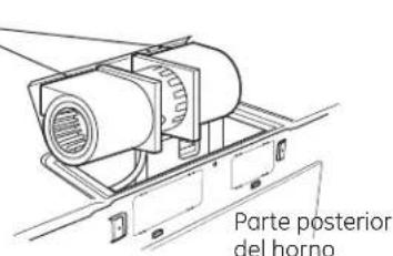
B4 CÓMO ADAPTAR EL SOPLADOR PARA EL ESCAPE POSTERIOR EXTERIOR
1 Retire el tornillo del motor del soplador que sostiene el plato soplador sobre el horno. Levante la parte frontal del plato soplador para instalar el soplador.
2 Cuidadosamente tire del soplador. Los alambres se extenderán lo suficiente como para permitirle que usted ajuste la unidad del soplador.
3 Rote la unidad 180° en sentido contrario a las agujas del reloj. Antes de la rotación Después de la rotación
4 Suavemente remueva los alambres de las ranuras. Redirija los alambres a través de las ranuras en el otro lado de la unidad del soplador.
Antes de redirigirlos Después de redirigirlos
Alambres dirigidos a través del lado derecho

Alambres dirigidos a través del lado izquierdo
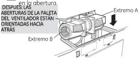
5 Ruede la unidad del soplador 90° de forma tal que las aberturas de la paleta del ventilador estén orientadas hacia la parte posterior del horno.

6 Localice los dos platos removibles en el panel posterior del horno, cerca de la parte superior del horno. Usando tijeras, cuidadosamente corte el área de telaraña de los dos agujeros lado a lado (que aseguran los platos removibles al horno). Corte las cuatro telarañas en ambos platos removibles posteriores; esto permitirá que el flujo de aire del ventilador escape hacia la parte posterior del horno.
A PRECAUCIÓN: Cerciórese de recortar los extremos filosos de las aberturas después de remover los platos.
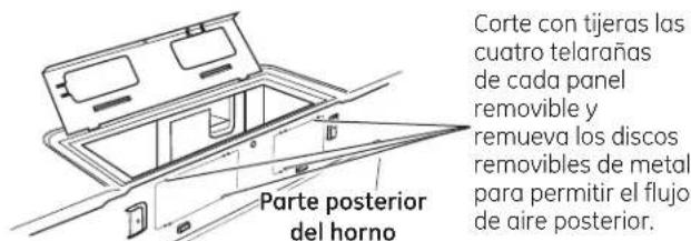
7 Coloque la unidad del soplador de nuevo
ADVERTENCIA: Existe riesgo de descargas eléctricas que pueden ocasionar lesiones o la muerte. No empuje ni extienda el cableado de la unidad de ventilación. Asegúrese de que los cables no posean cortes.
NOTA: Las aberturas de la salida de la unidad de ventilación deben coincidir con las aberturas de salida de la parte trasera del horno de microondas.
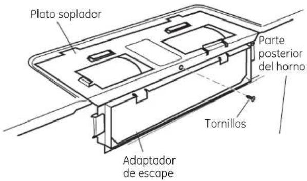
8 Pegue el adaptador de escape a la parte posterior del horno deslizándolo en las guías en la parte superior central de la parte posterior del horno.

Empuje firmemente hasta que esté en las orejillas de cierre inferiores. Tanga cuidado de asegurarse de que la bisagra del regulador de tiro esté instalada de forma que esté en la parte superior y que el regulador de tiro gire libremente.
9 Cierre el plato soplador de modo que se cierre sobre la lengüeta superior del adaptador del escape. Asegure el mismo con el tornillo retirado anteriormente.
B5 CÓMO MONTAR EL HORNO
APRECAUCIÓN: A fin de evitar el riesgo de lesión personal (lesión en la espalda u otras lesiones debido a peso excesivo del horno de microondas) o daños sobre el producto, deberá contar con la ayuda de dos personas para instalar este horno de microondas.
IMPORTANTE: No tome ni use la manija durante la instalación.
ADVERTENCIA: Riesgo de
Descarga Eléctrica. Puede ocasionar lesiones o la muerte: si instala la unidad con encimeros de metal, cubra el agujero del extremo del cable de suministro de corriente con aislante para el cable del suministro de corriente.
IMPORTANTE: Si no se usan bloqueadores de filtro, se podrán producir daños en la caja debido al ajuste excesivo de los tornillos.
NOTA: Cuando se encuentre montando el horno, enrosque el cable eléctrico a través del agujero en el fondo del gabinete superior. Manténgalo tenso a través de los Pasos del 1-3. No pellizque el cable ni tire del horno por el cable.
3 Insete un tornillo de autoalineación a través del agujero central superior del gabinete. Asegure el horno temporalmente girando el tornillo por lo menos dos vueltas completas después de que las roscas hayan agarrado. (Luego quedarán totalmente apretadas).
Frente del gabinete
4 Pegue el horno a la parte superior del gabinete.
5 Inserte 2 tornillos (1/4"-28 × 2 5/8") autoalineables a través de los agujeros exteriores del horno. Gire dos vueltas completas en cada tornillo.

6 Apriete los dos tornillos exteriores hacia la parte de arriba del horno. (Mientras aprieta los tornillos, mantenga el horno en su lugar contra la pared y el gabinete superior.)
7 Instale los filtros de grasa. Ver el Manual del Propietario que viene con el horno.
C RECIRCULACIÓN (Sin conducto de ventilación)
PERSPECTIVA GENERAL DE LA INSTALACIÓN
C1. Pegue el plato de montaje a la pared
C2. Prepare el gabinete superior
C3. Ajuste el soplador
C4. Monte el horno
C5. Instale el filtro de carbonilla (se suministra con JNM1951, DVM1950 y PNM1971 modelos)

C1 CÓMO ADHERIR LA PLACA DE MONTAJE A LA PARED

Pegue el plato a la pared usando los tornillos basculantes. Por lo menos un tornillo de madera debe ser usado para pegar el plato al poste de la pared.
1 Remueva las mariposas del basculante de los tornillos.
2 Inserte los tornillos en el plato de montaje a través de los agujeros diseñados para ser insertados en la pared de mampostería seca y pegue otra vez las mariposas de 3/4 " en cada tornillo.
Para usar los tornillos basculantes:
3 Coloque el plato de montaje contra la pared e inserte las alas de mariposa en los agujeros de la pared para montar el plato.
NOTA: Antes de apretar los tornillos basculantes y los tornillos de madera, cerciórese de que las orejillas en el plato de montaje toquen el fondo del gabinete cuando son empujadas contra la pared y de que el plato esté centrado apropiadamente debajo del gabinete.
PRECAUCIÓN: Tenga cuidado de evitar pellizar sus dedos entre la parte posterior del plato de montaje y la pared.
4 Apriete todos los tornillos. Tire del plato en dirección opuesta a la pared para ayudar a apretar los tornillos.
C2 USE LA PLANTILLA DEL GABINETE SUPERIOR PARA LA PREPARACIÓN DEL GABINETE SUPERIOR
Deberá perforar agujeros para los tornillos de apoyo superiores y un agujero suficientemente grande para que el cable eléctrico quepa.

- Lea las instrucciones sobre la PLANTILLA DEL GABINETE SUPERIOR.
- Péguela debajo del gabinete superior.
- Taladre un agujero, siguiendo las instrucciones en la PLANTILLA DEL GABINETE SUPERIOR.
PRECAUCIÓN: Use gafas de seguridad cuando perfore los agujeros en el fondo del gabinete.
C3 CÓMO ADAPTAR EL SOPLADOR PARA LA RECIRCULACIÓN
NOTA: El adaptador de escape con soplador no es necesario para los modelos de recirculación. Quizás desee guardarlos para posibles usos futuros.
1 Con cuidado empuje hacia usted la unidad del soplador. Los cables se extenderán lo suficiente como para permitirle ajustar la unidad del soplador.
2 Cuidadosamente tire del soplador. Los alambres se extenderán lo suficiente para permitirle que usted ajuste la unidad del soplador.
ANTES: LAS ABERTURAS DE LA PALETA DEL VENTILADOR ESTÁN ORIENTADAS HACIA ARRIBA

3 Ruede la unidad del soplador 90° de forma tal que las aberturas de la paleta del ventilador estén orientadas hacia el frente del microondas.

DESPUÉS: LAS ABERTURAS DE LA PALETA DEL VENTILADOR ESTÁN ORIENTADAS HACIA ADELANTE
NOTA: Cerciórese de que los alambres permanecen encaminados en las ranuras del marco del motor.
4 Coloque la unidad del soplador de nuevo en la abertura.
ADVERTENCIA: Existe riesgo de descargas eléctricas que pueden ocasionar lesiones o la muerte. No empuje ni extienda el cableado de la unidad de ventilación. Asegúrese de que los cables no posean cortes.

5 Cierre el plato soplador. Asegure el mismo con el tornillo retirado anteriormente.


CÓMO MONTAR EL HORNO

APRECAUCIÓN: A fin de evitar el riesgo de lesión personal (lesión en la espalda u otras lesiones debido a peso excesivo del horno de microondas) o daños sobre el producto, deberá contar con la ayuda de dos personas para instalar este horno de microondas.
IMPORTANTE: No tome ni use la manija durante la instalación.
ADVERTENCIA: Riesgo de Descarga Eléctrica. Puede ocasionar lesiones o la muerte: si instala la unidad con encimeros de metal, cubra el agujero del extremo del cable de suministro de corriente con aislante para el cable del suministro de corriente.
IMPORTANTE: Si no se usan bloqueadores de filtro, se podrán producir daños en la caja debido al ajuste excesivo de los tornillos.


CÓMO MONTAR EL HORNO
(continuación)
3 Inserte un tornillo de autoalineación a través del agujero central superior del gabinete. Asegure el horno temporalmente girando el tornillo por lo menos dos vueltas completas después de que las roscas hayan agarrado. (Luego quedarán totalmente apretadas).
Frente del gabinete

Inserte 2 tornillos (3/4"-28 x 2 5/8") autoalineables a través de los agujeros exteriores superiores del gabinete. Gire dos vueltas completas en cada tornillo.

5 Apriete los dos tornillos exteriores hacia la parte de arriba del horno. (Mientras aprieta los tornillos, mantenga el horno en su lugar contra la pared y el gabinete superior.)

6 Instale los filtros de grasa. Ver el Manual del Propietario que viene con el horno.
C5 CÓMO INSTALAR EL FILTRO DE CARBONILLA
1 Remueva los 2 tornillos en la parte superior del horno, justo encima de la rejilla usando un destornillador de estrella.
2 Abra la puerta.
3 Remueva la rejilla. Deslice la rejilla hacia la izquierda y luego empuje hacia afuera.

4 Insete el filtro en horno como se muestra hasta que se ajuste correctamente en su lugar. Descansará en un ángulo detrás de las orejillas inferiores frontales. Cuando está instalado correctamente, la malla del filtro debería estar visible desde el frente.

Filtro de carbonilla instalado
5 Remplace la rejilla y los dos tornillos superiores.
6 Cierre la puerta y vuelva a colocar el tornillo del lado izquierdo.
ANTES DE COMENZAR A USAR SU HORNO

ciórese de que el horno ha sido instalado de acuerdo con las instrucciones.
Instrucciones de Instalación

Lea el Manual del Propietario.
Manual de Usuario

Remueva todos los materiales de embalaje del horno.

Instale el aro rotatorio y con ruedas en la cavidad.

Reemplace el fusible de la casa o encienda de nuevo el interruptor.


GUARDE ESTAS INSTRUCCIONES PARA EL USO DEL INSPECTOR LOCAL.
Instrucciones de Instalación

Modelos de 120 V: Enchufe el cable eléctrico en un tomacorriente exclusivo de 15 a 20 amperios.

Donde haya un tomacorriente de pared estándar de dos espigas, resulta muy importante cambiarlo por un tomacorriente de pared de tres espigas con adecuada conexión a tierra, instalado por un electricista calificado.


- INSTALLATION INSTRUCTIONS
- ABOVE THE COOKTOP OVEN
- BEFORE YOU BEGIN
- CONTENTS
- GENERAL INFORMATION
- STEP-BY-STEP INSTALLATION GUIDE
- IMPORTANT SAFETY INSTRUCTIONS
- WARNING
- ELECTRICAL REQUIREMENTS
- 120 V MODELS
- HOOD EXHAUST
- OUTSIDE TOP EXHAUST (EXAMPLE ONLY)
- OUTSIDE BACK EXHAUST (EXAMPLE ONLY)
- EXHAUST CONNECTION
- MAXIMUM DUCT LENGTH
- DAMAGE - SHIPMENT/ INSTALLATION
- PARTS INCLUDED
- TOOLS YOU WILL NEED
- 1 AND #2 PHILLIPS SCREWDRIVER
- MOUNTING SPACE
- NOTES
- 1 | PLACEMENT OF THE MOUNTING PLATE
- REMOVING THE OVEN FROM THE CARTON/REMOVING THE MOUNTING PLATE
- OR
- C DETERMINING WALL PLATE LOCATION UNDER YOUR CABINET
- THE OVEN MUST BE LEVEL
- D ALIGNING THE WALL PLATE
- CAUTION
- INSTALLATION TYPES (CHOOSE A, B OR C)
- OUTSIDE TOP EXHAUST (VERTICAL DUCT)
- OUTSIDE BACK EXHAUST (HORIZONTAL DUCT)
- RECIRCULATING (NON-VENTED DUCTLESS)
- A OUTSIDE TOP EXHAUST (VERTICAL DUCT)
- INSTALLATION OVERVIEW
- A1 ATTACH THE MOUNTING PLATE TO THE WALL
- A2 USE TOP CABINET TEMPLATE FOR PREPARATION OF TOP CABINET
- A3 ASSEMBLE AND INSTALL ADAPTOR
- A4 MOUNT THE OVEN
- A4 MOUNT THE OVEN (CONTINUED)
- A5 ADJUST THE EXHAUST ADAPTOR
- A6 CONNECTING DUCTWORK
- B OUTSIDE BACK EXHAUST (HORIZONTAL DUCT)
- B1 PREPARING THE REAR WALL FOR OUTSIDE BACK EXHAUST
- B2 ATTACH THE MOUNTING PLATE TO THE WALL
- B3 USE TOP CABINET TEMPLATE FOR PREPARATION OF TOP CABINET
- B4 ADAPTING BLOWER FOR OUTSIDE BACK EXHAUST
- B5 MOUNT THE OVEN
- ATTACH THE MOUNTING PLATE TO THE WALL
- TO USE TOGGLE BOLTS
- USE TOP CABINET TEMPLATE FOR PREPARATION OF TOP CABINET
- C3 ADAPTING BLOWER FOR RECIRCULATION
- C4 MOUNT THE OVEN
- C5 INSTALLING THE CHARCOAL FILTER
- BEFORE YOU USE YOUR OVEN
- INSTRUCCIONES DE INSTALACIÓN
- HORNO PARA COLOCAR ENCIMA DE LA ESTUFA
- ANTES DE EMPEZAR
- CONTENIDO
- INFORMACIÓN GENERAL
- GUÍA DE INSTALACIÓN PASO POR PASO
- INSTRUCCIONES DE SEGURIDAD IMPORTANTES
- PRECAUCIÓN
- REQUISITOS ELÉCTRICOS
- MODELOS DE 120 V
- CAMPANA DE ESCAPE
- ESCAPE SUPERIOR EXTERNO (EJEMPLO SOLAMENTE)
- ESCAPE POSTERIOR EXTERNO (EJEMPLO SOLAMENTE)
- CONEXIONES DE ESCAPE
- LONGITUD MÁXIMA DEL CONDUCTO
- DAÑOS - ENVÍO / INSTALACIÓN
- PARTES INCLUIDAS
- HERRAMIENTAS QUE NECESITARÁ
- ESPACIO DE MONTAJE
- NOTAS
- 1 CÓMO COLOCAR EL PLATO DE MONTAJE
- A CÓMO REMOVER EL HORNO DEL EMBALAJE / CÓMO REMOVER EL PLATO DE MONTAJE
- B CÓMO ENCONTRAR LOS POSTES DE VIGA EN LA PARED
- O
- CÓMO DETERMINAR LA LOCALIZACIÓN DEL PLATO DE MONTAJE DEBAJO DE SU GABINETE
- EL HORNO DEBE QUEDAR NIVELADO
- 2 TIPOS DE INSTALACIÓN (ESCOJA A, B O C)
- A ESCAPE SUPERIOR EXTERIOR (CONDUCTO VERTICAL)
- B ESCAPE POSTERIOR EXTERIOR (CONDUCTO HORIZONTAL)
- C RECIRCULACIÓN (SIN CONDUCTO DE VENTILACIÓN)
- A | ESCAPE SUPERIOR EXTERIOR (CONDUCTO VERTICAL)
- PERSPECTIVA GENERAL DE LA INSTALACIÓN
- A1 CÓMO ADHERIR LA PLACA DE MONTAJE A LA PARED
- PARA USAR LOS TORNILLOS BASCULANTES
- A2 USE LA PLANTILLA DEL GABINETE SUPERIOR PARA LA PREPARACIÓN DEL GABINETE SUPERIOR
- A3 ENSAMBLAJE E INSTALACIÓN DEL ADAPTADOR
- A4 CÓMO MONTAR EL HORNO
- ADVERTENCIA: RIESGO DE
- A4 CÓMO MONTAR EL HORNO (CONTINUACIÓN)
- A5 CÓMO AJUSTAR EL ADAPTADOR DE ESCAPE
- A6 | CÓMO CONECTAR EL CONDUCTO
- B ESCAPE POSTERIOR EXTERNO (CONDUCTO HORIZONTAL)
- B1 CÓMO PREPARAR LA PARED POSTERIOR PARA EL ESCAPE POSTERIOR EXTERIOR
- B2 CÓMO ADHERIR EL PLATO DE MONTAJE A LA PARED
- B3 USE LA PLANTILLA DEL GABINETE SUPERIOR PARA PREPARAR EL GABINETE SUPERIOR
- B4 CÓMO ADAPTAR EL SOPLADOR PARA EL ESCAPE POSTERIOR EXTERIOR
- C1 CÓMO ADHERIR LA PLACA DE MONTAJE A LA PARED
- C2 USE LA PLANTILLA DEL GABINETE SUPERIOR PARA LA PREPARACIÓN DEL GABINETE SUPERIOR
- C3 CÓMO ADAPTAR EL SOPLADOR PARA LA RECIRCULACIÓN
- C5 CÓMO INSTALAR EL FILTRO DE CARBONILLA
- ANTES DE COMENZAR A USAR SU HORNO
Marka : GE
Model : JVM1950SRSS
Kategoria : Mikrofalówka