EAHF-L2-45-P-S - Ukategorisert Festo - Gratis bruksanvisning og manual
Finn enhetens veiledning gratis EAHF-L2-45-P-S Festo i PDF-format.

Brukerspørsmål om EAHF-L2-45-P-S Festo
0 spørsmål om dette apparatet. Svar på dem du kjenner, eller still ditt eget.
Still et nytt spørsmål om dette apparatet
Last ned instruksjonene for din Ukategorisert i PDF-format gratis! Finn veiledningen din EAHF-L2-45-P-S - Festo og ta den elektroniske enheten tilbake i hendene. På denne siden er alle dokumenter som er nødvendige for bruken av enheten din publisert. EAHF-L2-45-P-S av merket Festo.
BRUKSANVISNING EAHF-L2-45-P-S Festo
EAHF-L2-...-P-S
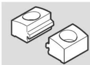
Profile mounting
natural_image
Two 3D-rendered rectangular electronic components with circular holes, shown in isometric view (no text or symbols)FESTO
Festo SE & Co. KG
Ruiter Straße 82
73734 Esslingen
Germany
+49 711 347-0
www.festo.com
Assembly instructions
8179869
2023-10c
[8179871]

8179869
Translation of the original instructions
© 2023 all rights reserved to Festo SE & Co. KG
1 Applicable documents
All available documents for the product → www.festo.com/sp.
| Document Product Content | |
| User documentation Actuator 2 Assembly |
Tab. 1: Applicable documents
2 Safety
2.1 Safety instructions
-Only mount the product on components that are in a condition to be safely operated.
2.2 Intended use
The profile mounting fastens an actuator 2 to a mounting surface via the basic profile.
2.3 Training of qualified personnel
Work on the product may only be carried out by qualified personnel who can evaluate the work and detect dangers. Personnel must have the relevant mechanical training.
3 Additional information
-Contact the regional Festo contact if you have technical problems
→ www.festo.com.
-Accessories → www.festo.com/catalogue.
4 Product Range Overview
4.1 Scope of delivery
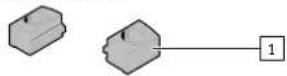
1 Profile mounting (2x)
Fig.1
4.2 Not in scope of delivery
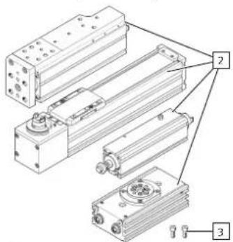
2 Actuator (1x):
Axis ELGC, ELFC;
Axis unit ELGS;
Mini slide EGSC;
Mini slide unit EGSS;
Quarter turn actuator DRRS;
Cylinder EPCC;
Cylinder unit EPCE, EPCS
3 Screw (2x)
Fig.2
5
Assembly
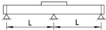
Fig. 3: Determine support spacings L and mounting points
- Determine the required support spacings L and mounting points of the actuator Other applicable documents.
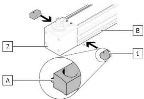
Fig. 4: Positioning profile mountings
- Position profile mountings 1 at the support points of the actuator 2. The lug (A) is in slot (B).
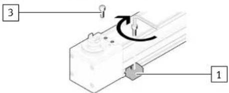
Fig. 5: Mounting actuator
1. Select the screws 3 suitable for the installation situation.
2. Fasten the profile mountings 1 on the mounting surface with screws 3. Observe maximum tightening torque.
| EAHF-L2-...-P-S -25 -45 | ||
| 3 Screw M4 | M5 | |
| Max. tightening torque [Nm] | 2.4 | 4.8 |
- Repeat the mounting steps for all mounting points.