DARD-L8-25-S - Ukategorisert Festo - Gratis bruksanvisning og manual
Finn enhetens veiledning gratis DARD-L8-25-S Festo i PDF-format.

Brukerspørsmål om DARD-L8-25-S Festo
0 spørsmål om dette apparatet. Svar på dem du kjenner, eller still ditt eget.
Still et nytt spørsmål om dette apparatet
Last ned instruksjonene for din Ukategorisert i PDF-format gratis! Finn veiledningen din DARD-L8-25-S - Festo og ta den elektroniske enheten tilbake i hendene. På denne siden er alle dokumenter som er nødvendige for bruken av enheten din publisert. DARD-L8-25-S av merket Festo.
BRUKSANVISNING DARD-L8-25-S Festo
Moment compensator DARD-L8

Instructions | Assembly
8084730
2018-02a
[8084732]

Translation of the original instructions
LOCTITE 243® is a registered trademark of its respective trademark holder in certain countries.
1 Further applicable documents
All available documents for the product → www.festo.com/pk.
Observe further applicable documents:
- Operating instructions of the linear drive 5
2 Safety
2.1 Safety instructions
- Before working on the product, switch off the power supply and secure it against being switched on again.
- Observe tightening torques. Unless otherwise specified, the tolerance is ± 10 %. Tightening torques → 5 Technical data.
- Observe the safety data sheet for the adhesive from the original manufacturer.
2.2 Intended use
Compensating element between the slide (A) of the linear drive 5 and the payload to be moved.
3 Product range overview
3.1 Scope of delivery
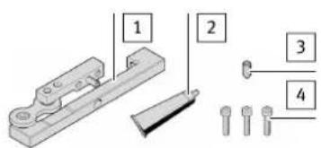
1 Moment compensator (1x)
2 Adhesive LOCTITE 243 (1x)
3 Threaded pin (1x)
4 Screw (3x)
Fig. 1
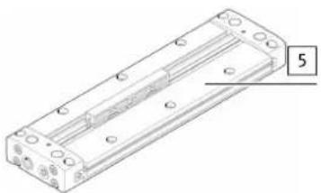
3.2 Not in scope of delivery
natural_image
Technical line drawing of a rectangular electronic component with mounting holes and a labeled section (no text or symbols beyond the number 5)5 Linear drive DLGF-G (1x)
Fig. 2
4 Mounting
Positioning the moment compensator
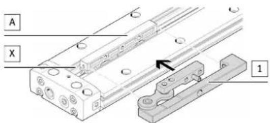
Fig. 3
- Place the moment compensator 1 opposite the sensor slot (X) flush with the slide (A).
The sensor slot (X) is freely accessible.
Attaching the moment compensator
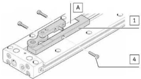
Fig. 4
- Use the screws 4 to attach the moment compensator 1 to the slide (A). Do not tighten screws 4.
Mounting the moment compensator
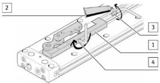
Fig. 5
- Apply adhesive 2 to the threaded pin 3.
- Screw the threaded pin 3 into the moment compensator 1.
- Tighten the threaded pin 3.
- Tighten the screws 4.
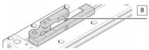
4.1 Mounting the payload
Hole for spring pin (B)
natural_image
Technical diagram of a mechanical assembly with labeled component B (no text or symbols present)Fig. 6
- Hole for spring pin (B) provided for centring the payload.

Recommended hole for spring pin (B): ∅ 5.2 +0.1 mm
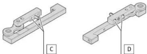
Mounting the payload on DARD-L8-20/25-S
natural_image
Two technical illustrations of a mechanical clamp or bracket component, labeled C and D (no text or symbols on the parts themselves)Fig. 7
- Mount payload with recommended screws using hole (C) or (D) on the moment compensator [1].
| Hole (C) Hole (D) | ||
| Hole thread M5 M5 | ||
| Recommended screws ≈ 2x M5-8.8 2x M4-8.8 ISO 4762 | ||
| Recommended tightening torques [Nm] 4.5 2.6 |
Tab. 1

When mounting the payload using hole (D), the threaded hole M5 (C) serves as a through hole for the screw M4.
Mounting the payload on DARD-L8-32/40-S
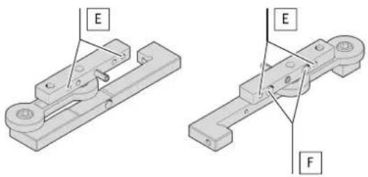
Fig. 8
- Mount payload with recommended screws using hole (E) or (F) on the moment compensator 1.
| Hole (E) Hole (F) | ||
| Hole thread M5 – | ||
| Recommended screws ⚫ 2x M5-8 | 8 2x M4-10.9 | ISO 4762 |
| Recommended tightening torques [Nm] 5 3.7 |
Tab. 2
5 Technical data
5.1 Screw sizes and tightening torques M
| DARD-L8 20 25 32 40 | |||||
| ISO 4762 | 3 M4x18 M4x18 M4x22 M4x22[4] | Screw | |||
| [Nm] 3 3 | 3.4 3.4 | ||||
| 3 Threaded pin | [Nm] | 1 | 1 | 1 | 1 |
Tab. 3