VFS-DH - Veggfeste Atdec - Gratis bruksanvisning og manual
Finn enhetens veiledning gratis VFS-DH Atdec i PDF-format.

Brukerspørsmål om VFS-DH Atdec
0 spørsmål om dette apparatet. Svar på dem du kjenner, eller still ditt eget.
Still et nytt spørsmål om dette apparatet
Last ned instruksjonene for din Veggfeste i PDF-format gratis! Finn veiledningen din VFS-DH - Atdec og ta den elektroniske enheten tilbake i hendene. På denne siden er alle dokumenter som er nødvendige for bruken av enheten din publisert. VFS-DH av merket Atdec.
BRUKSANVISNING VFS-DH Atdec
Installation Instructions
VFS-DH Freestanding | Double Horizontal
Component Checklist
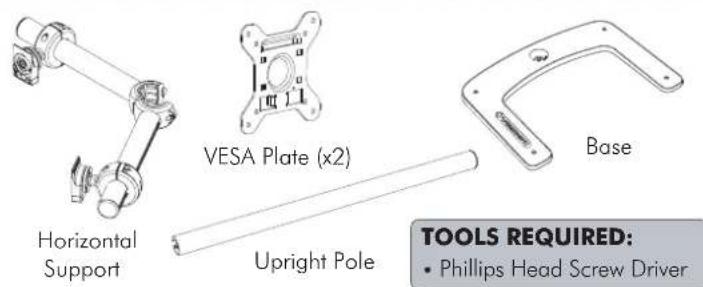
Hardware
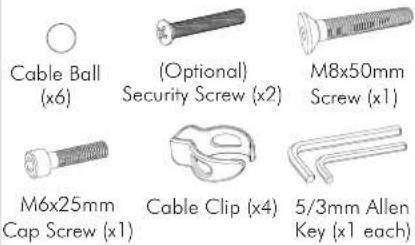
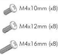
Display Mounting Screws
IMPORTANT INFORMATION:
! IMPORTANT - Install Freestanding/Double Horizontal as per Installation Instructions.
! Each Quickshift Donut supports a maximum weight of 12kg (26.5lbs).
! This product supports VESA mounting hole configurations: 75x75mm and 100x100mm.
! The manufacturer accepts no responsibility for incorrect installation.
Step 1. Check Components
Check you have received all parts against the component checklist and Hardware above.
Step 2. Attach Upright Pole to Base
Attach the Upright Pole to the Base as shown below. Ensure the Cable Slot faces towards the rear.
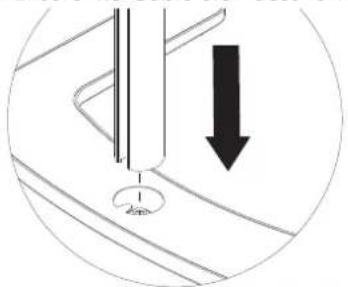
natural_image
Diagram showing a mechanical component with a downward arrow indicating motion or force, no text or symbols present.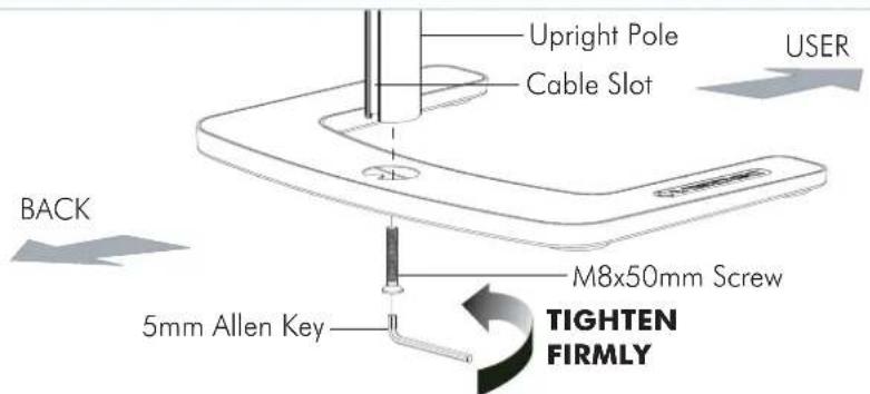
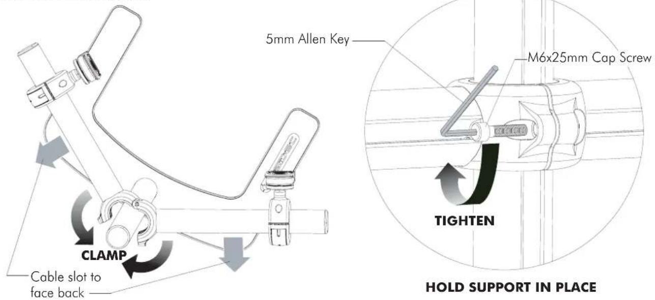
Step 3. Attach Horizontal Support
Clamp the Horizontal Support around the Upright Pole at the required height. Ensure the Slots in all the Poles are facing to the rear. Tighten support using the M6x25mm Cap Screw and 5mm Allen Key supplied.
Step 4. Attach the VESA Plate to your Display (Repeat steps 4 to 7 for each Display)
There are two mounting hole configurations:
- 75 x 75mm
- 100 x 100mm
from the Hardware supplied to suit your Display.
Top of Display
Back of Display
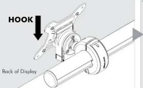
Step 5. Attach your Display to the Quickshift Donut
Hook the top of the VESA plate onto the Quickshift Mount.
Press and hold the Release Buttons. Gently push bottom of VESA Plate into Quickshift Mount. Release Buttons to lock in place.
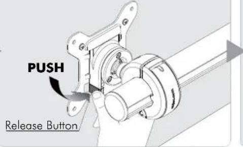
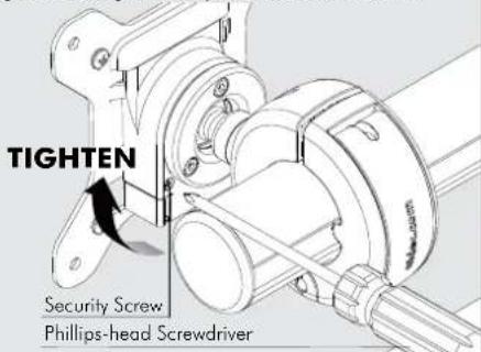
(Optional) Insert the Security Screw, and tighten using a Phillips-head Screwdriver.
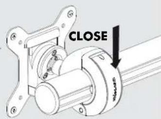
Step 6. Adjust the Height of the Quickshift Donut
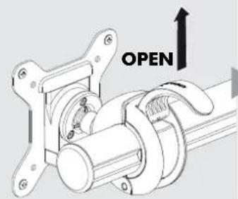
Open the lever to loosen the Quickshift Donut.
Slide the Quickshift Donut to desired position.
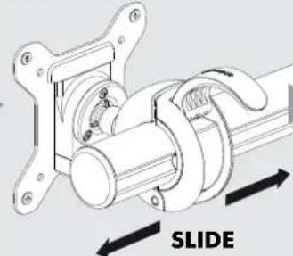
natural_image
Mechanical assembly diagram showing a sliding mechanism with no text or symbolsIf necessary, adjust the tension between the Donut and the Pole using the 5mm Allen Key supplied.
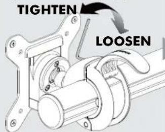
Close the lever to lock the Quickshift Donut in place.
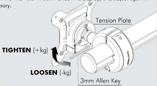
Step 7. Adjust the VESA Ball Mount
Position your Display to the desired viewing angle using the ±20^ tilt allowed by the VESA Ball Mount. To make any adjustments, use the 3mm Allen Key supplied. Apply half a turn at a time to each screw on the Tension Plate to adjust evenly. If the display does not hold its position, or is too resistant, adjust the Tension Plate located at the rear of the VESA Ball Mount. Check the display, and adjust again if necessary.
Step 8. Cable Management
Connect cables to your Displays, routing them down the rear of the poles. Push the cables into the slots, using either the Cable Balls or Cable Cilps to secure them to the pole as shown.
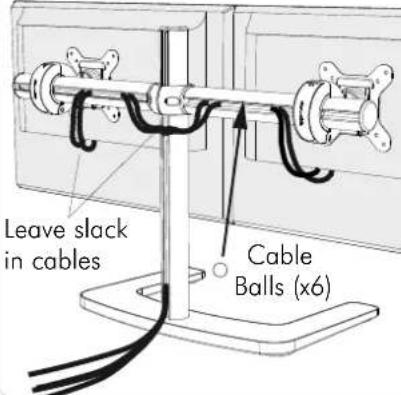
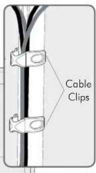
Note: Ensure enough slack is left in cables to allow for movement. When the slot in each pole cannot be used, use the supplied Cable Clips to secure the display cables.
Installation Complete