95-8153 - Kit voiture Metra - Gratis bruksanvisning og manual
Finn enhetens veiledning gratis 95-8153 Metra i PDF-format.

Brukerspørsmål om 95-8153 Metra
0 spørsmål om dette apparatet. Svar på dem du kjenner, eller still ditt eget.
Still et nytt spørsmål om dette apparatet
Last ned instruksjonene for din Kit voiture i PDF-format gratis! Finn veiledningen din 95-8153 - Metra og ta den elektroniske enheten tilbake i hendene. På denne siden er alle dokumenter som er nødvendige for bruken av enheten din publisert. 95-8153 av merket Metra.
BRUKSANVISNING 95-8153 Metra
INSTALLATION INSTRUCTIONS FOR PART 95-8153
APPLICATIONS
LEXUS LS SERIES
1995-2000
NOT FOR USE IN VEHICLES WITH FACTORY
NAVIGATION
95-8153
KIT FEATURES
• Double DIN Radio Provision
- Stacked ISO Mount Units Provision
KIT COMPONENTS
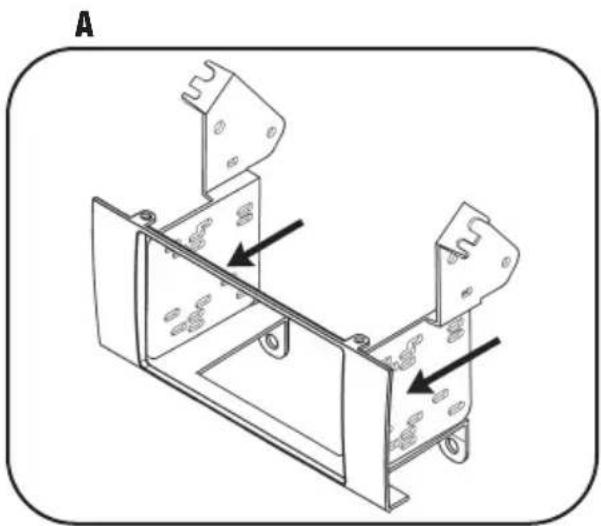
A) Double DIN Radio Housing B) Double DIN Brackets
natural_image
Interior view of a car dashboard with air filters and control buttons (no visible text or symbols)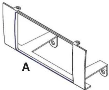
natural_image
Technical line drawing of a metal bracket with mounting holes and a labeled section A (no text or symbols beyond label)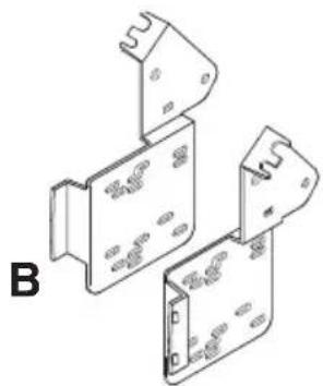
natural_image
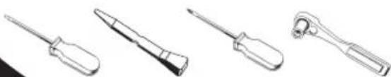
Isometric line drawing of three views of a device with mounting brackets (no text or symbols)TOOLS REQUIRED:
Small Flat Blade Screwdriver/ Panel Removal Tool
- Phillips Screwdriver - Socket Set
natural_image
Four different types of screwdrivers shown in line drawings (no text or labels)TABLE OF CONTENTS
Dash Disassembly
- Lexus LS Series 1995-2000 .... 1 .
Kit Assembly
- Double DIN Radio Provision ....2
- Stacked ISO Mount Units Provision 2
Final Assembly 3
*Note:
Refer also to the instructions included with the aftermarket radio.
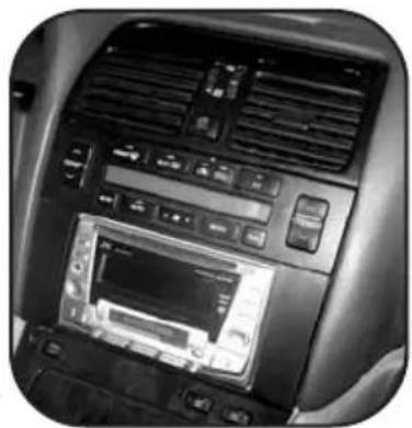
LEXUS LS SERIES 1995-2000
1 Disconnect the negative battery terminal to prevent an accidental short circuit.
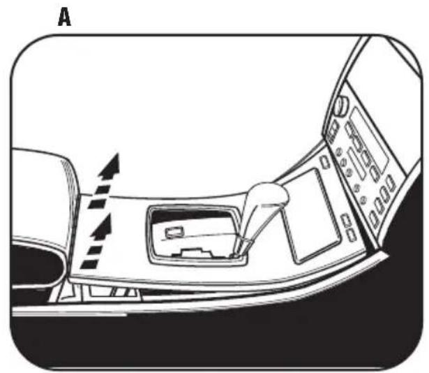
2 Starting at rear of panel surrounding the shifter carefully pry up and out to remove entire panel including ashtray. (Figure A)
3 Using a panel removal tool or small flat blade screwdriver gently pry out on the top of the A/C vent assembly (including clock) and remove. (Figure B)
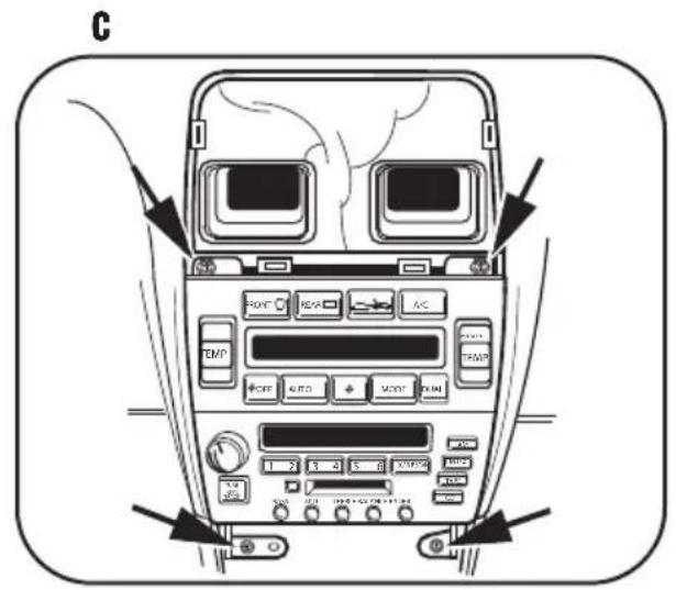
4 Remove (4) screws securing the factory radio/climate control assembly. Unplug and remove the assembly. (Figure C)
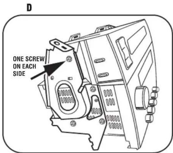
5 Remove (2) screws securing factory climate control to the assembly. Remove the climate control from the assembly and retain it for re-use during kit assembly. Figure D)
Continue to kit assembly.
natural_image
Interior view of a car dashboard with gear shift and control panel (no text or symbols)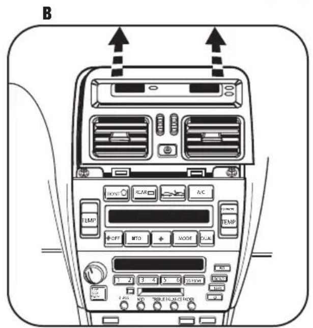
LEXUS LS SERIES 1995-2000
DOUBLE DIN RADIO
STACKED ISO MOUNT UNITS PROVISION
Note: Refer also to the instructions included with the aftermarket radio.
1 Snap the Double DIN Brackets onto the Double DIN Radio Housing. (Figure A)
2 Slide the factory climate controls into the Bracket/Radio Housing assembly aligning the top of the assembly with alignment pins in the bottom of the climate controls and secure using the factory hardware. (Figure B)
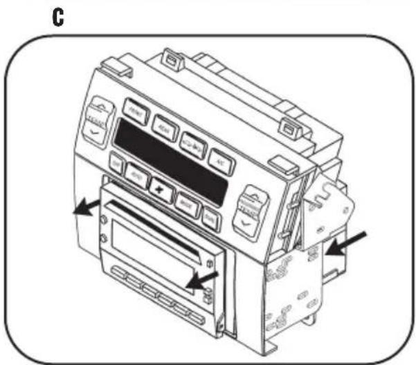
3 Slide the Double DIN or stacked ISO mount units into the bracket/radio housing assembly and secure the Double DIN or stacked ISO mount units to the assembly using the screws supplied with the Double DIN or stacked ISO mount units. (Figure C)
Continue to final assembly.
natural_image
Technical line drawing of a mechanical assembly with two components and directional arrows indicating movement (no text or symbols)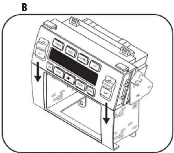
FINAL ASSEMBLY
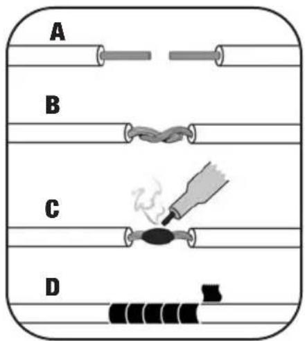
(A) Strip wire ends back 1/2"
B) Twist ends together
C) Solder
D) Tape
1 Locate the factory wiring harness in the dash. Metra recommends using the proper mating adapter and making connections as shown. (Isolate and individually tape off the ends of any unused wires to prevent electrical short circuit.)
2 Re-connect the negative battery terminal and test the unit for proper operation.
3 Reassemble radio and dash assemblies in reverse order of disassembly.
FINAL WIRING CONNECTIONS
Make wiring connections using the EIA color code chart shown below and the instructions included with the head unit. Metra recommends making connections as shown below; Strip, Splice, Solder, Tape. Isolate and individually tape off ends of any unused wires to prevent electrical short circuit.
METRA / EIA WIRING CODE
| 12V Ignition / Acc. . . . . . . . Red | Right Front (+) . . . . . . . . . . . . . . . . . . . . . . . . . . . . . . . . . . . . . . . . . . . . . . . . . . . . . . . . . . . . . . . . . . . . . . . . . . . . . . . . . . . . . . . . . . . . . . . . . . . . | |||
| 12V Batt / Memory. . . . . . . . . . . . . . . . . . . . . . . . . . . . . . . . . . . . . . . . . . . . . . . . . . . . . . . . . . . . . . . . . . . . . . . . . . . . . . . . . . . . . . . . . . . . . . . . . . . . | Right Front (-). . . . . . . . . . . . . . . . . . . . . . . . . . . . . . . . . . . . . . . . . . . . . . . . . . . . . . . . . . . . . . . . . . . . . . . . . . . . . . . . . . . . . . . . . . . . . . . . . . . . Ground. . . . . . . . . . . . . . . . . . . . . . . . . . . . . . . . . . . . . . . . . . . . . . . . . . . . . . . . . . . . . . . . . . . . . . . . . . . . . . . . . . . . . . . . . . . . . . . . . . . Power Antenna. . . . . . . . . . . . . . . . . . Blue | Left Front (+) . . . . . . . . . . . . . . . . . . . . . . . . . . . . . . . . . . . . . . . . . . . . . . . . . . . . . . . . . . . . . . . . . . . . . . . . Left Front (-). . . . . . . . . . . . . . . . . . . . . . . . . . . . . . . . . . . . . . . . . . . . White | ||
| Amp Turn-On. . . . . . . . . . . . . . . . . Blue / White | Right Rear (+) . . . . . . . . . . . . . . . . . . . . . . . . . . . . . . . . . . . . . . . . . . . . . . . . . . . . . . . . . . . . . . . . . . . . . . . . Amp Ground. . . . . . . . . . . . . . Black / White | Right Rear (-) . . . . . . . . . . . . . . . . . . . . . . . . . . . . . . . . . . . . . . . . . . . . . . . . . . . . . . . . . . . . . . . . . . . . . . . Illumination. . . . Orange | Right Rear (+) . . . . . . . . . . . . . . . . . . . . . . . . . . . . . . . . . . . . . . . . . . . . . . . . . . . . . . . . . . . . . . . . . . . . . . . . . . . . . . . . . Dimmer. . . . Orange / White | Left Rear (-) . . . . . . . . . . . . . . . . . . . . GreenGreen / Black |
*NOTE: When a Black wire is not present, ground radio to vehicle chassis. All colors may not be present on all leads due to manufacturer's specifications.
NOTES
NOTES
95-8153 INSTRUCTIONS