IP-A1MP - Mikrofon TOA - Gratis bruksanvisning og manual
Finn enhetens veiledning gratis IP-A1MP TOA i PDF-format.

Brukerspørsmål om IP-A1MP TOA
0 spørsmål om dette apparatet. Svar på dem du kjenner, eller still ditt eget.
Still et nytt spørsmål om dette apparatet
Last ned instruksjonene for din Mikrofon i PDF-format gratis! Finn veiledningen din IP-A1MP - TOA og ta den elektroniske enheten tilbake i hendene. På denne siden er alle dokumenter som er nødvendige for bruken av enheten din publisert. IP-A1MP av merket TOA.
BRUKSANVISNING IP-A1MP TOA
MICROPHONE PANEL IP-A1MP
Thank you for purchasing TOA's Microphone Panel.
Please carefully follow the instructions in this manual to ensure long, trouble-free use of your equipment.
1. SAFETY PRECAUTIONS
- Before installation or use, be sure to carefully read all the instructions in this section for correct and safe operation.
- Be sure to follow all the precautionary instructions in this section, which contain important warnings and/or cautions regarding safety.
• After reading, keep this manual handy for future reference.
Safety Symbol and Message Conventions
Safety symbols and messages described below are used in this manual to prevent bodily injury and property damage which could result from mishandling. Before operating your product, read this manual first and understand the safety symbols and messages so you are thoroughly aware of the potential safety hazards.

WARNING
Indicates a potentially hazardous situation which, if mishandled, could result in death or serious personal injury.

CAUTION
Indicates a potentially hazardous situation which, if mishandled, could result in moderate or minor personal injury, and/or property damage.

WARNING
When Installing the Unit
-
Do not expose the unit to rain or an environment where it may be splashed by water or other liquids, as doing so may result in fire or electric shock.
• Install the unit only in a location that can structurally support the weight of the unit and the mounting bracket. Doing otherwise may result in the unit falling down and causing personal injury and/or property damage. -
Since the unit is designed for indoor use, do not install it outdoors. If installed outdoors, the aging of parts causes the unit to fall off, resulting in personal injury. Also, when it gets wet with rain, there is a danger of electric shock.
- Do not mount the unit in locations exposed to constant vibration. The mounting bracket can be damaged by excessive vibration, potentially causing the unit to fall, which could result in personal injury.
- Use screws that are appropriate for the wall's structure and composition. Failure to do so may cause the unit to fall, resulting in material damage and possible personal injury.
- Use the specified plate in combination. Doing otherwise may cause the unit or component to fall off, resulting in personal injury.
- Take care that electrical lines are not pinched during installation. Pinched wires could potentially cause a fire or electrical shock.

CAUTION
When Installing the Unit
- Avoid installing the unit in humid or dusty locations, in locations exposed to the direct sunlight, near the heaters, or in locations generating sooty smoke or steam as doing otherwise may result in fire or electric shock.
- Avoid touching the unit's sharp metal edge to prevent injury.
2. SUMMARY AND FEATURES
The IP-A1MP Microphone Panel integrates a microphone, a call button and an indicator light. It can be installed in the optional mount box, and can be mounted either embedded under a cover or left exposed.
When used together with the IP Audio Series, the Microphone Panel can be used as a microphone for conversations or public address announcements.
3. NOMENCLATURE AND FUNCTIONS
![[Front] [Rear] Status indicator (green) Microphone Call button Terminals Control output Control input Microphone output Microphone volume control](/content/2026/05/1128499/images/dce6bc75f6dc3bec430348af8cace9acf3a03d704b08e1120d75805d20f04362.jpg)
- The Microphone Panel is powered by a phantom power supply (9 – 26 V DC).
• Audio from the microphone is output at line signal level and can be adjusted by the microphone volume control. - The status indicator is linked to the control input and lights green.
- Control output is linked to the Call button (momentary operation).
4. CONNECTIONS
![Terminals of this unit H C H H C E CONTROL MIC OUT MIC OUT VOL + LINE OUT H C E CTRL OUT CTRL IN H C 1 2 C Terminals of the IP-A1AF H C E LINE/MIC IN 0dB [PAD] LINE OFF[PHANTOM] 123 MIC ON] -20dB Decrease Increase LINE/MIC input volume control 1 : LINE 2 : 0 dB [PAD] 3 : ON [PHANTOM]](/content/2026/05/1128499/images/7cdbddd12f12f000cba9d1dfaae22e334896d3058100ecb317b5759816019e04.jpg)
Power is supplied to the unit by a phantom power supply (9 - 26 V DC). Before connecting the unit to the IP-A1AF, be sure that the Interface's DIP switch is set as shown in the figure above.
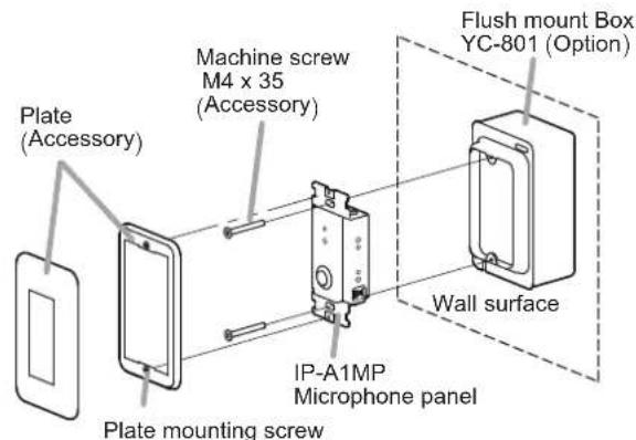
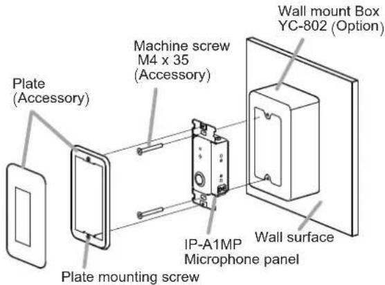
5. UNIT MOUNTING
[Flush mount]
[Wall mount]
6. SPECIFICATIONS
The specifications of this product are available in TOA DATA Library (https://www.toa-products.com/international/).
Scan the QR Code at right with your mobile phone camera to access the WEB site and search for this product number (IP-A1MP).

- Accessories
Plate 1
Plate mounting screw (Preinstalled on the plate) ..... 2
Machine screw M4 x 35 2
- Optional products
Flush mount Box: YC-801
Wall mount Box: YC-802