Fit Utility Unit - Kontor Anthro - Gratis bruksanvisning og manual
Finn enhetens veiledning gratis Fit Utility Unit Anthro i PDF-format.

Brukerspørsmål om Fit Utility Unit Anthro
0 spørsmål om dette apparatet. Svar på dem du kjenner, eller still ditt eget.
Still et nytt spørsmål om dette apparatet
Last ned instruksjonene for din Kontor i PDF-format gratis! Finn veiledningen din Fit Utility Unit - Anthro og ta den elektroniske enheten tilbake i hendene. På denne siden er alle dokumenter som er nødvendige for bruken av enheten din publisert. Fit Utility Unit av merket Anthro.
BRUKSANVISNING Fit Utility Unit Anthro
Step 7
Attaching the Base Assembly to the Leg
Align the Base Assembly on the Legs as shown. Secure the Base Assembly to the Legs by inserting a Bolt through Tube Washer and attach loosely
Repeat for the remaining three Bolts, then tighten all the fasteners (see steps 2 and 4).

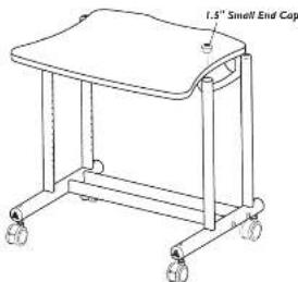
Step 8
The Final Step
Carefully rotate your Utility Unit onto its Casters. Insert the four 1.5" End Caps into the Legs.
Congratulations! Your assembly is complete
Please return the enclosed Registration Card to receive our product updates, new catalogs, and sale flyers; you'll be entered to win our monthly drawing of \$300.00 of Anthro product
Thank you for choosing Anthro
Questions?

1-800-325-3841

24"/30"/36" wide Utility Unit Assembly Instructions

Hello!
Thank you for choosing Anthro
Before beginning assembly of your Utility Unit, please take a moment to review the parts listed below to verify that your shipment is complete.
Please review the assembly instructions of all Andro products you purchased and are planning to include in this installation prior to beginning this assembly
To make the assembly of your Utility Unit even easier, we have included all of the required tools. The handy Hex Driver Bit can be used in your electric drill in place of the Hex Driver
Hex Driver ^3 375-5000-00 Hex Driver Bit ^3 375-5003-00 8 oz. Rubber Mallet 375-5022-00
Detailed views of all Hardware are provided with each Assembly Step
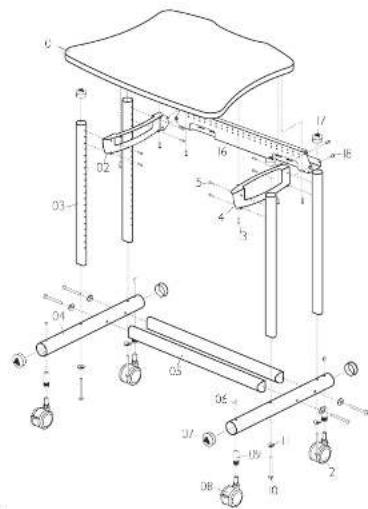
Component part list for part #'s
FY2429zz/xx3, FY3029zz/xx3, FY3629zz/xx3
| 01-Work Surface | Qty. | /see hwnly. |
| 24" Wide Work Surface | (FY2429zz/xx3) | 100-6431-00 |
| 30" Wide Work Surface | (FY3029zz/xx3) | 100-6440-00 |
| 36" Wide Work Surface | (FY3629zz/xx3) | 100-6535-00 |
| 02-Fit Small Support Y | Qty. | 225-2015-00 |
| 03-22.875" Vertical Leg | Qty. | 125-5213-00 |
| 04-21" Base Tube | Qty. | 125-5215-00 |
| 05-Cross Tube | Qty. | /see hwnly. |
| 24" Wide Base Tube | (FY2429zz/xx3) | 125-5218-00 |
| 30" Wide Base Tube | (FY3029zz/xx3) | 125-5219-00 |
| 36" Wide Base Tube | (FY3629zz/xx3) | 125-5220-00 |
| 06-Insert Screws | Qty. | 325-5052-00 |
| 07-2" Large End Caps | Qty. | 175-5157-00 |
| 08-3" Locking Castors | Qty. | 150-5053-00 |
| 09-Caster Inserts | Qty. | 525-5032-00 |
| 10-1⁄2"-18 Fit Boltz | Qty. | 325-5194-00 |
| 11-Fit Tube Washer | Qty. | 225-2050-60 w 225-3522- |
| 12-3" Non-Locking Casters | Qty. 7 | 150-5052-00 |
| 13-1" Wood Screw | Qty. 8 | 325-5106-00 |
| 14-Fit Small Support X | Qty. | 225-2014-00 |
| 15-Support Screws | Qty. 9 | 325-5010-00 |
| 16-Back Trough | Qty. | (see below) |
| 24" Wide Back Trough | (FY2479zxzx3) | 225-2789-00 |
| 30" Wide Back Trough | (FY3029zxzx3) | 225-2290-00 |
| 36" Wide Back Trough | (FY3679zxzx3) | 225-2291-00 |
| 17-1.5" Small Caps | Qty. 4 | 175-5156-00 |
| 18-1"-20 Button Head Screws | Qty. 4 | 325-5003-00 |
All Screw quantities listed here are the minimum needed for your Utility Unit assembly. There may be a few extra Screws Included, which are not counted in the Parts List
Archro Corporation Technology Furniture 10-50 SW Monoset Drive Tuaiatir, Oregon 97062
anthro.com
1-800-325-3841
SAVE THESE INSTRUCTIONS.
Rev. D January 2001
24"/30"/36" wide Utility Unit Assembly Instructions
Questions? 1-800-325-3841
Step
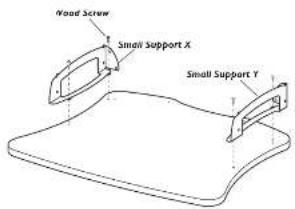
Attaching Shelf Supports to the Shelf
Place your Work Surface onto the floor with the predrilled holes facing upward
Position the Small Supports onto the Work Surface and align two of the holes on each Small Support with the predrilled holes on the Work Surface
Secure each Small Support to the Work Surface using two Wood Screws per Support

14" Wood Screw
325-5106-0C
Step 2
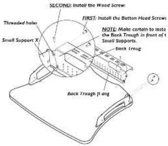
Attaching the Back Trough to the Shelf Support
Place the Back Trough onto the Work Surface, between the installed Small Supports (from Step 1).
Align the two threaded holes on each end of the Back Trough with those on both Shelf Supports. Carefully thread one Button Head Screw through the Shelf Support and into the Back Trough, but don't tighten all the way Repeat for the remaining three Button Head Screws, and leave them all a slightly loose.
Align the holes in the bottom fl ange of the Back Trough wi the pre-drilled holes on the Work Surface. Attach the Back Trough to the Work Surface using two Wood Screw:

"Wood Sow
325-3106-01

(10'-20 X .50") Button Head Screw
325-5001-DC
Step 3
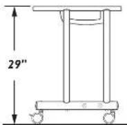
Determine the Shelf Height
Determine the best height for your Shelf. These instructions will place your Shelf 29" from the Floor using the standard 3" Casters.
For a final Shelf height that is lower than 29", adjust on hole down for each inch of variance desired
NOTE: Your Shelf location may be changed after your Utility Unit has been completely assembled by referring to Step 4
Antiro Corporation Technology Furniture 10450 SW Manhasset Drive Tualatin, Oregon 9706
Step 4
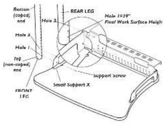
Attaching the Legs to the Work Surface
The Utility Unit Legs have a coped (curved) end and a fl at end. The fl at end attaches to the Work Surfac
Attach a Leg to the rear of the Shell using two Support Screws. Insert the screws through the holes in the Shel Support and into the first and third holes on the leg; leave the screws a little loose. Repeat for the other three legs.

Support Screw 325-5010-00
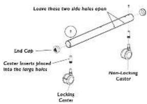
Step 5
Assembling the Base Tube
Install two caster Inserts into each Base Tube and secur with one Insert Screw per Caster Insert.
Insert one Locking Caster and one Non-locking Caster into the Inserts on each Base Tube. The Non-lockin Caster should be near the two side holes
Insert 2" End Caps into the ends of each Base Tube

Insert Screw (screw pink patch or end) 325-5052-06
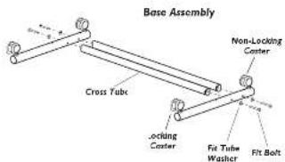
Step 6
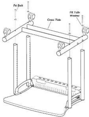
Attaching the Cross Tubes to the Base Tube
Attach a Cross Tube to a Base Tube by inserting Fit Bolt through a Tube Washer, then insert the Bolt through the Base Tube and carefully thread into the Cross Tub
Repeat this procedure for other Cross Tube. Then tighten all -it Bolts.

17-18 X 3.5" Fe Bolt 325-5194-00

Fit Tube Wash 125-3050-00 or 725-3522-00
anthro.com