
WV-QED100G - Rookmelder i-PRO - Gratis gebruiksaanwijzing en handleiding
Vind de handleiding van het apparaat gratis WV-QED100G i-PRO in PDF-formaat.


| Type product | Plafondmontagebeugel |
| Merk | i-PRO |
| Model | WV-QED100G |
| Geschikt voor | i-PRO FTZ type binnenbewakingscamera's |
| Installatietype | Inbouw in plafond (dubbele plafond geschikt) |
| Afmetingen (beugel) | 470 mm x 370 mm |
| Gewicht | Ca. 800 g |
| Omgevingstemperatuur | -10 °C tot 60 °C |
| Materiaal | Metaal |
| Bevestigingsmethode | Met ankerbouten (M10 aanbevolen) |
| Veiligheidsvoorziening | Veiligheidskabel en veiligheidshoek meegeleverd |
| Inclusief accessoires | Sjabloon A, sjabloon B, veiligheidshoek, bevestigingsschroeven |
| Niet inbegrepen | Ankerbouten (M10), camera, kabels |
| Benodigd gereedschap | Boormachine, schroevendraaier, momentsleutel |
| Aanbevolen aandraaimoment | 0,65 N·m (cameraschroeven), 0,5 N·m (montageplaat) |
| Maximale belasting | Afhankelijk van ankerbouten; treksterkte >6x totaalgewicht |
| Toepassing | Binnen, plafondmontage |
| Onderhoud | Periodiek controleren op vastzittende schroeven en bevestigingen |
| Garantie | Zie garantievoorwaarden van i-PRO |
| Veiligheidswaarschuwing | Alleen installeren door gekwalificeerd personeel |
Veelgestelde vragen - WV-QED100G i-PRO
Gebruikersvragen over WV-QED100G i-PRO
0 vraag over dit apparaat. Beantwoord die u kent of stel uw eigen vraag.
Stel een nieuwe vraag over dit apparaat
Download de handleiding voor uw Rookmelder in PDF-formaat gratis! Vind uw handleiding WV-QED100G - i-PRO en neem uw elektronisch apparaat weer in handen. Op deze pagina staan alle documenten die nodig zijn voor het gebruik van uw apparaat. WV-QED100G van het merk i-PRO.
GEBRUIKSAANWIJZING WV-QED100G i-PRO
i·PRO
Operating Instructions
Included Installation Instructions
Ceiling Mount Bracket
Model No. WV-QED100

- Before attempting to connect or install this product, please read these instructions carefully and save this manual for future use.
- The external appearance and other parts shown in this manual may differ from the actual product within the scope that will not interfere with normal use due to improvement of the product.
i-PRO Co., Ltd. assumes no responsibility for injuries or property damage resulting from failures arising out of improper installation or operation inconsistent with this documentation.
“

i-PRO Co., Ltd.
https://www.i-pro.com/
© i-PRO Co., Ltd. 2022

Ns0522-0 Printed in China
Caution:
| Before attempting to connect or operate this product, please read these instructions carefully. |
Notice:
| This product is not suitable for use in locations where children are likely to be present.Do not install this product in locations where |
| ordinary persons can easily reach. |
| • For information about a group and other part |
| - For information about screws and other parts required for installation, refer to the corre- |
| sponding section of this document. |
Precautions
■ Do not use this product except with suitable cameras.
Failure to observe this may cause a drop resulting in injury or accidents.
■ Refer installation work to the dealer.
Installation work requires technique and experience. Failure to observe this may cause fire, electric shock, injury, or damage to the product.
Be sure to consult the dealer.
■ The measures of protection against a fall of this product shall be taken.
Failure to observe this may cause a drop resulting in injury or accidents. Be sure to install the safety wire
■ The screws and bolts must be tightened to the specified torque.
Failure to observe this may cause a drop resulting in injury or accidents.
■ Install the product securely on a ceiling in accordance with the installation instructions. Failure to observe this may cause injury or accidents
■ Do not rub the edges of metal parts with your hand.
Failure to observe this may cause injury.
When using this product, also read the "Precautions" described in the operating instructions for the camera to be attached.
About notations
Some functions are expressed with the following notations in this document
Clear dome cover
Smoke dome cover
Preface
This product is a ceiling mount bracket that is designed to mount the indoor PTZ type camera on a ceiling. This bracket can be used for an area with weak pull-out strength such as plasterboard in a double ceiling, and the embedded type makes the visible part of the camera smaller.

The latest information about the supported cameras
Specifications
| Ambient temperature: -10 °C to | +50 °C [14 °F to 122 °F] |
| Dimensions: Maximum diameter | ø190 mm x 212 mm (H) |
| 7-15/32 inches × 8-11/32 inches (H) \ |
| Mass: | Approx. 800 g (1.77 lbs.) |
| Finish: Main body: Surface treatment steel sheet |
| Decorative cover: ABS resin i-PRO white |
| Dome cover: Acrylic resin (C) |
| 5 (Transmittance: approx. 50 %) |
Precautions for installation
In order to prevent injury, the product must be securely mounted to the ceiling according to the Installation Guide of this product.
■ This product is designed to be used indoors.
This product is not operable outdoors. Do not expose this product to direct sunlight for hours and do not install the product near a heater or an air conditioner. Otherwise, it may cause deformation, discoloration and malfunction. Keep this product away from water and moisture.
■ Installation area for this product
| Make sure that the installation area is strong enough to hold the total weight of the camera assembly before installation. The installation area shall have 180 mm (7-3/32 inches) or more space behind the ceiling. | 180 mm[7-3/32 inches]or more |
| The thickness of the ceiling board for installation can range between 9 mm [11/32 inches] and 40 mm [1-9/16 inches]. | Ceiling board: between 9 mm [11/32 inches] and |
■ Make sure to remove this product if it will no longer be used.0 mm (1-9/16 inches)
Standard Accessories
| Operating Instructions (this document)......1 pc. |
| The following are for installation |
| Safety wire* | 1 pc. | Template A | 1 pc |
| Safety wire angle* | 1 pc. | Template B | 1 pc |
| Inner cover (WV-QAT100) | 1 pc |
* The product is shipped in a state where the safety wire is attached to the safety wire angle.
Other items that are needed (not included)
| Anchor bolt (M10)* | 2 pcs. | Nut (M10) | 6 pcs. |
| * One anchor is used for securing the mounting base, and the other anchor is used for connecting the safety wire. (See Step 4) | |||
IMPORTANT
- Prepare anchor bolts according to the material and strength of the area where the product is to be installed. The pull-out strength of the anchor bolt shall be more than 5 times of the total weight of the installed devices (including the camera body, ceiling mount bracket, anchor bolts, and all other parts).
Parts and functions
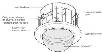
* If a tiepin type microphone is used, mount the microphone on the rubber-made microphone stand. Unless the microphone is used, cut the rubber with a nipper or conduct another treatment.
Installation
Refer to the operating instructions of the camera for details on the camera installation (including the camera mounting, cable connection and adjustment).
Step 1
① Loosen the fixing screw (unremovable) to be used for cover fall prevention.
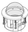
② Tum the decorative cover counterclockwise to unhook it from the hooks (3 positions) of the camera mounting bracket, and remove it from this bracket.
③ Take the inner cover out.

Step 2
Remove the camera mounting plate.
Remove the screws (M4, 3 pcs.) and remove the camera mounting plate by turning it counterclockwise.
Remove the tab of the camera mounting plate (a) from the hole of the mounting base (b) (2 positions)
- Keep the removed screws until using them in Step 14.

① Make 4 holes of 12 mm (15/32 inches) in
diameter. ② Remove the center part from the template. ③ Make a hole of 160 mm (6-5/16 inches) in diameter.
* The hole shape is shown below.


Step 4
Install two anchor bolts (M10 recommended) into the concrete ceiling.
① Determine the anchor bolt length (for mounting base) by use of Template B (accessory). ② Position the nut (locally procured) by use of Template B. (The distance between the bottom surfaces of the ceiling board and nut shall be 136 mm {5-11/32 inches).)

IMPORTANT:
When the existing anchor bolt is used as an anchor bolt for connecting the safety wire, make sure that the distance between the anchor bolt and camera mounting position is 1 m (3.28 feet) or less.
Step 5
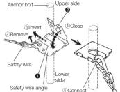
Mount the safety wire angle (accessory) on the anchor bolt for the
① Mount a nut so that the safety wire angle is secured on the anchor bolt.
② Remove the safety wire from the safety wire angle.
③ Insert the groove of the portion ① of
④ Close the safety wire angle while inserting the groove of the portion ⑨ of the safety wire angle into the anchor bolt.
⑤ Connect the safety wire to the safety wire angle again
⑥ Engage the nut from beneath, and secure the safety wire angle with top and bottom nuts.
⑦ Engage another nut from beneath to tighten and secure the nut that was engaged from beneath in ⑥ in a double nut fashion
12
Note: - When the existing anchor bolt that has been installed is used for connecting the safety wire, the use of 2 spacer nuts is helpful.



Step 6
Attach the safety wire.
Attach the safety wire to the mounting base as shown in the illustration below.

Step 7
Insert the mounting base into the hole made in Step 3.
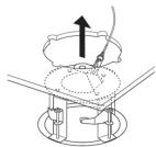
Step 8
Secure the mounting base.
① Engage the top of the mounting base with the anchor bolt for the mounting base. ② Secure the mounting base by turning the ceiling board fixing screws (4 places) clockwise. Turning the ceiling board fixing screws clockwise provides ceiling board tightening between the bottom of the mounting base and ceiling board fixing bracket resulting in mounting base securing.
Recommended tigtening torque: 0.78 N·m (0.58 lbf·ft)

IMPORTANT:
- When securing the mounting base on the ceiling, make sure that the four ceiling board fixing brackets are open as shown in the figure.
③ Secure the top of the mounting base with double nuts (locally procured).
[Non-Text]
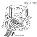
Step 9 Prepare the cables.
Run the cables from the cable inlet.
IMPORTANT:
- The cables shall be run from the opposite side of the FRONT mark. Failure to observe this makes the cables unconnectable since the camera faces the opposite side.
Step 10 Attach the inner cover.
① Remove the side covers from the camera main body. (Both the left and right sides)

flowchart
graph TD
    A["Top Top"] --> B["Top Middle"]
    B --> C["Bottom Left"]
    C --> D["Bottom Right"]
② Attach the inner cover.

■ When removing the inner cover
Release the claws on the inner surface on both the left and right sides one by one and then remove the inner cover.

Step 11 Mount the camera on the camera mounting plate.
① Put the camera onto the camera mounting plate with aligning the lock plate of the camera with the guide of the camera mounting plate and inserting the center of the camera mounting plate with the center of the camera, and turn the camera clockwise. ② Secure the camera with the camera fixing screw (M3: camera accessory).
Recommended tightening torque: 0.68 N·m (0.5 lbf·ft)
IMPORTANT:
- Be sure to mount the camera with holding the stationary portion of the camera.

Step 12 Connect the safety wire to the camera.
Connect the safety wire locked on the mounting base to the camera. Make sure that the apical ring of the safety wire is engaged with the safety wire hook of the camera by pulling the safety wire after connection.

Step 13 Connect the cables to the camera.
Step 14 Mount the camera mounting plate and camera on the mounting
① Align the marks (A to A and B to B) between
the camera mounting plate and mounting base.
② Mount the camera mounting plate on the
mounting base with aligning of the camera mounting plate with "START " of the mounting
mounting plate with START V of the mounting base.
③ Turn the camera mounting plate until of the
camera mounting plate aligns with "END ∇" of
the mounting base, and then temporarily fix by
hooking the hooks of the camera mounting
plate into the holes of the mounting base.
④ Tighten the 3 screws that were removed in Step 2
Recommended tightening torque: 1.6 N·m {1.18 lbf·ft}
IMPORTANT:
- Do not let the cables be caught during
installation work

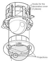
Step 15 Mount the decorative cover.
① Mount the decorative cover on the camera mount-
ing plate with engaging the projections of the
decorative cover with the hooks for the decorative
cover. ① Try the descriptive cover also using while passing
② Turn the decorative cover clockwise while pt the projections upward and fix it temporarily.
IMPORTANT:
• The i-PRO logo, shall be aligned with the
FRONT mark.
Fixing screw to be used for cover fall prevention
Step 16 Tighten the fixing screw to be used for cover fall prevention.

Recommended tightening torque: 1.6 N·m (1.18 lbf·ft)
Step 17
Remove the protection sheet from the dome cover.
Note:
- When the tilt angle of the camera is almost level, the upper side of images will be hidden by this product reflecting on the screen. In such a case, adjust the tilt angle. Refer to the Operating Instructions of the camera for further information.
[EMPTY]
- i·PRO
- Operating Instructions
- i-PRO Co., Ltd.
- Precautions
- About notations
- Preface
- Specifications
- Precautions for installation
- Standard Accessories
- Other items that are needed (not included)
- IMPORTANT
- Parts and functions
- Installation
- Step 1
- Step 2
- Remove the camera mounting plate.
- Step 4
- Install two anchor bolts (M10 recommended) into the concrete ceiling.
- IMPORTANT:
- Step 5
- Mount the safety wire angle (accessory) on the anchor bolt for the
- Step 6
- Attach the safety wire.
- Step 7
- Insert the mounting base into the hole made in Step 3.
- Step 8
- Secure the mounting base.
- Step 9 Prepare the cables.
- Step 10 Attach the inner cover.
- Step 11 Mount the camera on the camera mounting plate.
- Step 12 Connect the safety wire to the camera.
- Step 13 Connect the cables to the camera.
- Step 14 Mount the camera mounting plate and camera on the mounting
- Step 15 Mount the decorative cover.
- Step 16 Tighten the fixing screw to be used for cover fall prevention.
- Step 17
Merk : i-PRO
Model : WV-QED100G
Categorie : Rookmelder