FT34 - Verrekijkers PARD - Gratis gebruiksaanwijzing en handleiding
Vind de handleiding van het apparaat gratis FT34 PARD in PDF-formaat.

Gebruikersvragen over FT34 PARD
0 vraag over dit apparaat. Beantwoord die u kent of stel uw eigen vraag.
Stel een nieuwe vraag over dit apparaat
Download de handleiding voor uw Verrekijkers in PDF-formaat gratis! Vind uw handleiding FT34 - PARD en neem uw elektronisch apparaat weer in handen. Op deze pagina staan alle documenten die nodig zijn voor het gebruik van uw apparaat. FT34 van het merk PARD.
GEBRUIKSAANWIJZING FT34 PARD
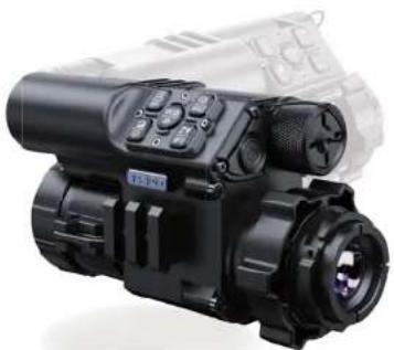
PARD
natural_image
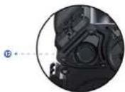
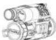
Black and white photo of a surveillance camera with dual lenses and a sensor (no visible text or symbols)USA
User Manual
Multipurpose Thermal Imaging
FT34/FT34-LRF
Scan To Enjoy Privilege

Scan The QR Code To Join Our Membership
1 Extend warranty
2 Enjoy 1 on 1 expert service
3 Get the product experience officer opportunity
CONTENTS
- Introduction 01
- Precautions 01
- Package Contents 02
- Description & Key Features 03
- Specifications 04
B.Components & Controls 08 - Installation 12
8.Operation instruction 21
0.1 Shortcut Mode 22
8.2 Manu Mode 26 - Statement 41
INTRODUCTION
Thank you for your continued support and choosing PARD FT34/FT34-LRF thermal front clip-on series. Please read this manual carefully before using the device for the first time. Please follow the instructions in this manual to avoid any damage caused by improper usage.
After reading, please keep this manual for the future reference.
This manual provides step-by-step instructions on how to use your thermal monocular and is intended for your reference only.
PARD reserves the right to amend this manual at any time without prior notice to individual users. For the most up-to-date information, we recommend visiting PARD's official website. PARD reserves the final interpretation right of this manual.
PRECAUTIONS
- Please remove the insulating tape on the battery before first use. It is recommended to use a fully charged
Inchiffon Battery, with a rated voltage of 3.5V.
Please turn off the device and remove the battery when it's not in use for more than 10 days, and store the device & battery in a dry and safe place.
- Do not look directly to avoid eye damage when in use.
- Be extra cautious and handle the device with care during use or transportation. It is recommended to use the original packaging during transportation.
- Do not use the device to focus directly on strong sources of light such as the sun or electric welding. The detector may be damaged and it will void the warranty.
- Avoid lens scratches and damage caused by oil or chemical contamination of the lens. Keep the lens cap on when not in use.
- The device should be placed in a cool, dry, and ventilated environment without strong electromagnetic fields, and the working environment temperature should not be lower than (-20°C/4°F) or higher than (50°C/122°F). - Do not disassemble the device without authorization. If you encounter any problems, please contact our after-sales
team and report them on our official website. Failure to do so will render the warranty service null and void.
- Attention I All PARD night-vision and thermal imaging devices require a license to be exported outside the
PACKAGE CONTENTS
| Contentsicon Quantity | ||
| PT34/PT34URF Multipurpose Thermal Imaging 1 | ||
| 3.7V 18650 Rechargeable lithium ion battery 1 | ||
| Adsulator 1 | ||
| Cyclohex 1 | ||
| Casket 4 | ||
| Type-C cable | 2 | |
| 2Allen wrench | ||
| 2Closh bag | ||
| User's manual | 1 | |
| Warranty card | 1 | |
DESCRIPTION & KEY FEATURES
T'e FT34/CFT34/NIF is a compact, light 't multifunctional t'ermal imaging device, 5"ic" can be used as a "and" old monocular, a Seapon mounted t'ermal imaging scope or as a front clip/on to existing optical scopes. T'e 12um, NETO-25NiK C'ermal imaging sensor can detect subtle temperature differences, giving you "ig" or image resolution and clarity. As a "thermal scope at t'ermal imaging monocular, it is accompanied by specialized lenses. Thereafter, it incorporates ionous functions including ballistic calculation, catering to bot" arising and scaring needs.
Key features
① Outpurpose for being a t*ermal dip/on,
monocular or thermal imaging scope
7 No need to Gero Has a copy on
2 Dlt/sensmje sensor twil
1200 yd Hig ^* /precision range 1000
- Hi-ared image LA-ANCEMENT AGONE-HI BILDA
6 Compact body, compact design
7 Quick conversion of optical scope to
thermal imaging scope
Ballistic calculation
9 201
⑩ lecoil resistance recording
① IP67
18550 ft*ium/ion rec*argable battery
SPECIFICATIONS
| Model FT34 | FT34-LRF | |
| Sensor | ||
| Detector Resolution(pixel) | 384*288 | 384*288 |
| Pixel Size(μm) | 12*12 | 12*12 |
| NETD | ≤25mK (60.025°C) | ≤25mK (60.025°C) |
| Frame Rate(Hz) | 50 | 50 |
| Human Detection Distance(m) | 1400 | 1400 |
| Vehicle Detection Distance(m) | 2600 | 2600 |
| Optics | ||
| Objective Lens(mm) | 35 | 35 |
| Optical Magnification(x) | 3.5 | 3.5 |
| Digital Zoom(x) | 2/4/6/8 | 2/4/6/8 |
| Continuous Digital Zoom | ||
| Field of View (horizontal) | 7.5° | 7.5° |
| Model | FT34 | FT34 LRF |
| Field of View (vertical) | 5.6' | 5.6' |
| Field of View (diagonal) | 9.4' | 9.4' |
| Eye Reiler(mm) | 30 | 30 |
| Diopter Adjustment(D) | +5 | +5 |
| Display | ||
| Type | OLED | OLED |
| Reticle Style | 6 | 6 |
| Resolution(pixel) | 1440*1080 | 1440*1080 |
| Scene Mode | Cry/Rain/Forest | Cry/Rain/Forest |
| Image Mode | WT HOT/BK HOT/EDGE/RD HOT/IN HOT/SKY | WT HOT/BK HOT/EDGE/RD HOT/IN HOT/SKY |
| Photo / Video | ||
| Photo Resolution(pixel) | 2592*1944 | 2592*1944 |
| Photo Format | JPG | JPG |
| Video Resolution(pixel) | 1024*768 | 1024*768 |
| Video Format | Jmp4 | Jmp4 |
| Storage(68) | TF card 80ax 128 J | TF card 80ax 128 J |
| Model | FT34 | FT34-LRF |
| Image Engine | PAID IEA | PAID IEA |
| Main Function | ||
| LRF Detection Range(yd) | NCA | 1200 |
| PIP | Yes | Yes |
| Gyroscope | Yes | Yes |
| Loop Recording | Yes | Yes |
| E-compass | Yes | Yes |
| Hot Track | Yes | Yes |
| Shutter | Mcc'anical s'utter | Mcc'anical s'utter |
| Microphone | Yes | Yes |
| Firmware Upgrade | Yes | Yes |
| Power Supply | ||
| Battery Type | Ji/Jon 18650kt | Ji/Jon 18650kt |
| Output Voltage(V) | 3.7 | 3.7 |
| Model | FT34 | FT34-LRF |
| Operating Time(h) | ≤5 | ≤5 |
| External Power Supply Type-C | Type-C | |
| Environmental Characteristic | ||
| Degree of Protection | IP67 IP67 | |
| Operating Temp(°C/°F) | -20~50/-4~122 | -20~50/-4~122 |
| Racoll Resistance(J) | 6000 | 6000 |
| Material | ||
| Housing | Aluminium alloy Aluminium alloy | |
| Objective Lens(mm) | All/glass multi/coated lens All/glass multi/coated lens | |
| Measurement | ||
| Product Dimension (L * W * H, mm) | Wit* eyepiece 142k80k77Wit* adapter 154k79k82 | Wit* eyepiece 150k60k80Wit* adapter 165k79k84 |
| N.W/pcs (Without Battery, g) | Wit* eyepiece 370Wit* adapter 480 | Wit* eyepiece 410Wit* adapter 520 |
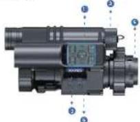
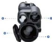
COMPONENTS & CONTROLS
FT34-LRF
natural_image
Diagram of a black handheld device with labeled parts (no text or symbols present)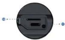
| No. | Name |
| 1 | Power Indicator |
| 2 | Button panel |
| 3 | Battery cap |
| 4 | Clip-on eyepiece |
| 5 | Picatenny rail |
| 6 | Torchlight |
| 7 | Rangchindor( LRP module) |
| 8 | Objective lens cap |
| 9 | Objective lens |
| 10 | TF card slot |
| 11 | Type-C charging port |
| 12 | Power/Sleep |
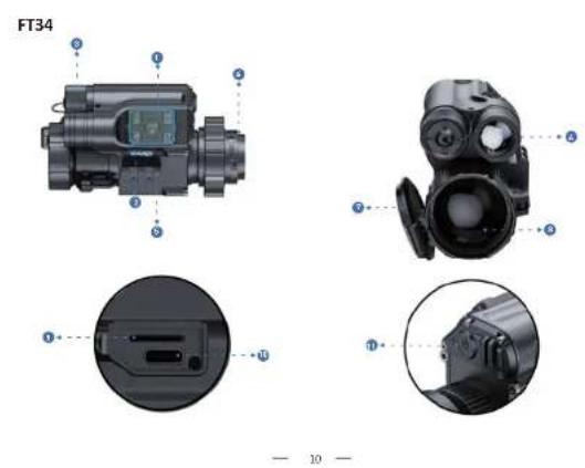
| No. | Name |
| 1 | Power Indicator |
| 2 | Button panel |
| 3 | Battery cap |
| 4 | Clip-on eyosieces |
| 5 | Ficatiny tail |
| 6 | Torchlight |
| 7 | Objective lens cap |
| 8 | Objective lens |
| 9 | TF card slot |
| 10 | Type-C changing port |
| 11 | Power/Sleep |
INSTALLATION
1. Unboxing
Before using t*is delice, please do t*a foliaSing:
- Open t*e box and remote t*e device.
- Check to ensure t* at t*e package contents listed above are all included in t*e box.
- Check 'e deliver for any damage to 'e display, body, lens, buttons, etc.
- Oste sure t* at t* e objective lens and eyepiece are clean & functioning properly.
Notes: If any accessories are missing or damaged, please contact PAID after/sales service.
2. Battery Installation and Startup
The battery installation steps are as follows:
2.1 Unsore5 t*e battery cap clacSize and pull out t*e battery.
2.2 Tear off t*e insulating tape on t*e positive terminal of t*e battery.

2.3 insert t*a battery, ensure t*e posit|e B+) side goes in first and tig*ten t*e battery cap in a clockwise direction.
2.4 long press t'e poser button for about 3 seconds to poser t'e delice. BT'e poser indicator lights up and PAID logo is displayed on t'e screen, 5"x" means t'e delice is ready for use.)
Note:
Please use a single 18650 rec*angeable lithium/on battery rated 3.77 voltage.
② Please pay attention to align the buckle interface.
Do not put battery into fire.
Do not put device into Sater 5"en t"e battery cap is open.
Do not disassemble the dejice sit out authorisation.
Do not pierce t ^a e delice Sit ^b s ^a ara objects.
Battery s^ could be kept out of reach of children, and the positive and negative terminals of the battery
s could be installed correctly.
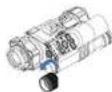
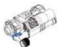
3. Adaptor Installation
To ensure the best user experience, Se significantly recommend using our original adapter included in 1*e product packaging, as s*05n in picture 1.
Notes: W'en t* is dejice is used as a front dip/on, it needs to be installed 5it* an adapter to be used normally.

natural_image
Technical line drawing of a mechanical assembly with exploded view (no text or symbols)Take out the thermal imaging device, one adapter, inserts and an Allen Srenc ^4 out of the box.
Before installing t ^a e adaptor, turn on t ^a e device to see t ^a e clear icons on screen.
③ Wrap 1/2 layers of insulating tape on the eyepiece using for protection.
4 Dock and rotate t*e t*ermal imaging body into t*e adapter lens and adapter, and loser t*e adapter locking lejer.
5 According to t°a diameter of t°e light sign front end, select a single Sas" or a combination of multiple Sas"ers,
put t'e socket on t'e lig't sig't front, observe 5'et'er t'e display is in t'e center position from t'e lig't sig't
eyepiece, and adjust the level, press the adapter lock handle.
4. Mount Installation
To ensure t*e best user experience, Se *lg*ly recommend using our original mount, as s*a5n in Picture 2.
Note: W*en t*Is dejice is used as a 1*ermal rifle scope, accessories need to be purchased additionally.

Picture 2
Take out t'e t'ermal imaging device from t'e box, and t'e extra purchased mounting bracket and accessories: Amount big*soning screw5s, Allan Sronc® BD4.0mm and gaskets).
Position t'e delice upside deSn, place t'e end of t'e mount 5in t'so sre5s facing t'e objectile lens direction, attack t'e flat side of t'e mount on t'e bottom of t'e delice. Adjust t'e mount to your preferred position B'attention: t'e end of t'e mounting bracket facing t'e eyepiece cannot exceed t'e junction edge of t'e rubber ergus and t'e focusing ring. Failure to folo5t's direction may result in eye damage during use).
3 Install 3 screws in the front, middle and rear positions.
① Use t* = Allen Srect* and big ten t* e scrss clickwise
⑤ If there is any *oriental deflation, you may use t* e 50 s*ims to adjust. elect t* e appropriate s*lm s*Ge and place it in t* e corresponding scr5 position, t* en repeat t* e aboje steps.
5. Diopter Focusing
T* is device only needs dipter focusing S* on it is used as t*ermal imaging scope or *and* ele monocular.
Diopter focusing is aimed to enable users St* different jisions to clearly see t*e content displaying on t*e screen, as depicted in Picture 3.
After posering t*e device, rotate t*e diopter focusing 5*eel so t*at you can see t*e screen clearly
② As long as you can clearly see t*e cross*air and text on t*e display, t*e diapter focusing setting *as been completed.
Please note: T*e image is not seen clearly after adjustment as t*e objective lens is not properly focused yet.
Picture 3
6. Objective Lens Focusing
Before you focus t*a object je lens, ensure t*at t*e clopter focusing *as been completed.
2 Aim at t*e target you Sant to see, and turn t*e focus lejor of t*e objechje lens until you can see t*e target image, as s*obn in picture 4.

Picture 4
7. Compass Calibration
7* is device only needs to do compass calibration 5* en it is used as t*ermal imaging scope or *and*eld monocular.
- 17 -
After t*e eyapiece is focused, please use t*e "figure 8 pattern met*od" to calibrate t*e compass // Users are required to tilt and moje t*e dcjice in a figure 8 motion until t*e compass is calibrated, as s*oSn in t*e Picture 5.
Note: t*e system at t*is product. Still be automatically recognized by t*e eyepiece, if t*e de)ce is used as gun sig*ring eyepieces, t*e screen menu. Still *aje icons suc* as compass; If it is used as a light sig* piece, t*e icon is not displayed

Picture 5
8. Zeroing (Reticle Adjustment)
leotide Adjustment refers to aligning t*e reticle Sit* t*e point of impact at a Garing distance, so t*at t*e position of t*e aiming point at t*is specific distance corresponds Sit* t*e point of impact of t*e bullet.
Note: T* is device only needs to be Geraing 5* on it is used as t* normal imaging scope or * and * old monocular. ① Set the target: at t* a target at Geraing distance and ensure t* at t* a device can obtain a good image.
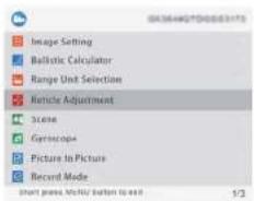
2 Enter to sub-menu option "Reticle Adjustment": In t*e some screen mode, press [Key 5] to enter t*e menu mode and press [Key 4] to moje t*e cursor to t*e reticle adjustment setting option. Press [Key 2] to enter t*e sub/menu interface, as s*pSn in t*e Picture 6.
Profile setting: After entering t* a lattle Adjustment setting page, press [Key 3]C[Key 4] in"172" item sSccting from A/E to create a net Gering profile or edit an existing one, as s*05n in t* a Picture 7.
Picture 7 Picture 5
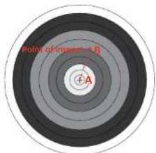
6 Shoot: Fire a 1st s*ot aiming at t*e center of t*e target BA, ensuring t*at you can see a clear point of impact 00) on t*e screen after t*e s*ot *as been taken, as s*o5n in t*e Picture 8.
Picture 8
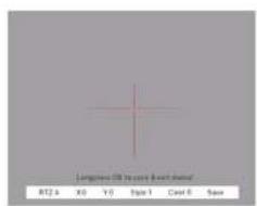
5 Adjust zero value: in t'e same page, press [Key 2] to t'e second item "X.0", press [Key 3] or [Key 4] to freeGo t'e screen; T'en, adjust t'e "X" and "Y" values Sit* [Key 3] [Key 4] and sSirc* betSeen t'em by [Key 2] until t'e reticle center BA) aligns Sit* t'e impact point BB) on t'e display screen.
Save and exit: Press [key 2] to t'c "a/o" item, use [Key 3][Key 4] to set "a": t'. After t'o setting is completed, press [Key 2] to safe and exit. T'e actual point of impact is mojoed to t'e center point of t'e reticle. B7'e reticle is always at t'e center of t'e screen, 51c can maximize t'e use of t'e entire observation field.)
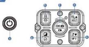
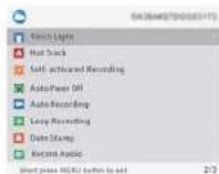
Operation Instruction
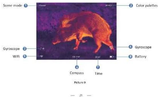
- Shortcut Mode
Picture 10
| Single press | Press and hold | Double press | |
| Power/Sleep | Power or/alf | Key 1 | |
| Key 2 | Confirm/Tako a photo | Record video/Save video | |
| Key 3 | Up/Enlarge | View files | Turn on/Off picture in picture |
| Key 4 | Ranging / Ballistic calculation | Turn off WiFi | Turn on/Off touchlight |
| Key 5 | Menu/Back | Back | Switch scene modes |
| Key 6 | Switch image mode | Shutter correction |
Explanation :
Key 1
- Single press:
Press [Key 1] to put delice into sleep mode 5^th en t'e delice is on. Press [Key 1] again to Sake up delice from sleep mode.
- Press and hold:
Press and *old [Key 1] to turn on C off t*e delice.
Key 2
- Single press:
Home screen mode: press [Key 2] to take p*ato.
- Press and hold:
Home screen mode: press and *old [Key 2] to record a video. Press and *old [Key 2] again to sale the video and exit.
Key 3
- Single press:
① Home screen mode: press [Key 3] to Goom in 2xC4xC6xC8x times.
(2) Menu mode: press [Key 3] to scroll up or adjust the relevant option settings.
2. Press and hold;
Home screen mode: press and hold [Key 3] to view video and picture files saved on the memory card:
① Press [Key 3][Key 4] to switch between files.
⑤ Press [Key 2] to play/pause the saved videos.
② When playing videos, press [key 3] to fast forward or rewind 2x/4x/6x/8x times, press and hold [key 5] to exit
② From the (Key 5) button to create the following settings:
④ Press the [Key 3] button to access the following settings.
1|Delete
2) Protect
3|Slide Show:
- Delete Current
- Lock Current
• 2 seconds
- Delete All
- Unlock Current
- 5 seconds
- Lock All
- Unlock All
- Press and hold the [Key 5] button to return the home screen.
3. Double press
Home screen mode: Home screen mode: double press [Key 3] to turn on/off the picture-in-picture function.
Key 4
1. Single press:
① Home screen mode: press [Key 4] to start the LRF range detection function. The distance will be measured and
displayed automatically
⑤ Manu mode: press [Key4] to scroll down or adjust the relevant option settings.
- Press and hold:
Home screen mode: press and hold [Key 4] to close WIFI.
- Double press:
Home screen mode: double press [Key 4] to turn on or turn off the torch light.
Key 5
- Single press:
① Home screen mode: press [Key 5] to open/close the menu interface.
② Menu mode: in menu mode press [Key 5] to go back to the home screen.
- Press and hold:
Home screen mode: press and hold. [Key 5] to switch between City/Forest/Rain scene modes.
Key 6
- Single press:
Home screen mode: press [Key 6] to switch image modes:
WT HOT/BK HOT/EDGE/RO HOT/IN HOT/SKY
- Double press
Home screen mode: double press [Key 6] to perform a shutter calibration action.
2. Menu Mode
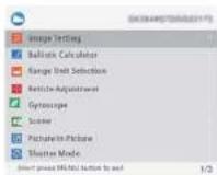
Home screen mode: single press [Key 5] to enter the menu mode to set various function options (the shortcut key function is invalid at this time), as shown in Picture 11.
2.1. Image Setting
Users can adjust the image contrast, brightness, detail and mode under this setting.
① Press [Key 4] to move the cursor to the Image Setting option, press [Key 2] to enter the sub-menu.
Press [Key 2] to switch between Contrast / Brightness / Detail/ Mode options, and press [Key 3]/[Key 4] to adjust
the option value.
② Press and hold [Key 2] to exit. Upon the next startup, the device will maintain the saved image settings.
Image default settings: contrast value is 105, Detail is 2, sharpness is 2 and the mode value is 0.

Picture 11
2.2 Ballistic Calculator
T*roug* t*e ballistic algorithm, t*e relevant parameters affecting t*e bullet trajectory are calculated and t*en an auxiliary cross*air is indicated on t*e side, for accurate s*outing, as s*osen in Picture 12.
① Press (Key 3) [Key 4] to mole t*e cursor to t*e Ballistic Calculator setting option, press (Key 2) to enter t*e submanu interface.
② Press t* a [Key 3]C [Key 4] to move t* e cursor to select t* e ParametersOnCoOff t* e ballistic calculator sub/option, and t* an press t* a [Key 2] to sale or enter.
(2) After entering t'e Ballistic Calculator Parameter settings, press t'e [Key 2]C[Key 5] to move up or do 5n to select t'e parameters option you 5ant to change, and press t'e [Key 3]C[Key 4] to adjust t'e value of t'e corresponding parameter.
Parameter Settings Guide:
Parameters
| Building Class | |
| Velocity (ft) | 300 |
| Bucket Weight | 46.0 |
| Bucket BC | 1,465 |
| All Order (ft) | 6000 |
| Temperature (°C) | 58 |
| Slope (H/m2) | 0.74 |
| Zone Range (yds) | 42 |
| Reference Point Stage And Color | > |
Long press a OR to never export
(四) 2018年6月29日 星期五、周四的星期日
Picture 12
• Ballistic Data: There are 5 sets of profiles BA/E] that can be sealed.
- Velocity: It is t^th measurement of bullet travel speed after it is fired from your rifle, expressed in "meters per second" BMCs) or "feet per second" BFCs), 5^th can be measured by using professional testing equipment.
- Bullet Wt: refers to t'e 5cigt of t'e bullet, expressed in 'grains' Bg] or 'grains' Bgr], 3*ic can be obtained from t'e specifications section of t'e purchased bullets.
- Bullet BC: Ballistic coefficient (BBC) of a bullet is a measure of its ability to overcome air resistance in flight. Data can be obtained from t*e specifications of t*e ourc*ased bullets.
- Altitude: refers to t*e altitude of t*a location, expressed in "meters" 8m] or "fast" Bft], 5*c* is one of t*a important indicators affecting air density in ballistic calculations and can be measured by using professional testing equipment.
- Temperature: Refers to the local temperature, expressed in "Celsius" (°C) or "Fahrenheit" (°F), which is also one of the important indicators affecting air density in ballistic calculations, and can be measured by using professional testing equipment.
- Scope Ht: Refers to the height difference between the optical axis of the sight and the barrel, expressed in
"millimeters" [mm] or "inches" [inch], which can be measured by professional testing equipment. *Zero range: Refers to the unit distance expressed in "meter" [m] or "yard" (yds), usually set to 100m or 100yds,
users can adjust according to their own preferences.
- Reference Point Shape and Color: Press [Key 3] to enter the option, press [Key 2] to switch between shape and color sub-options: press [Key1]/[Key4] to select the desired shape and colors. Three origins of Shape and Color
Sub options: press [key2], [key4], to select the desired shape and color. Three options of shape can be chosen by sub-options are available, press [Key 5]. To confirm and return to the previous page, as shown in Picture 13.
(3) After adjusting your preferred settings, long press [Key 2] to save and return to the home screen. Long press [Key 5] to exit without saving.
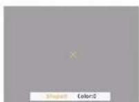
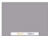
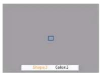
Pichre 13
3. Range Unit Selection
Users can sSite* betSeen "meter" or "yard" and t*e range unit can be updated instantly to meet t*e user's preference.
Press [Key 3]C[Key 4] to mo/e t*e cursor to t*e range unit selection option, and press [Key 2] to enter t*e sub/menu. Press [Key 3]C[Key 4] to c*pose betSeen "imotor" or "yard", t*en press [Key 2] to sa/e and return to t*e previous
4. Reticle Adjustment
leticle adjustment refers to aligning the reticle 5it* the point of impact at a common s'ooting distance, so it* at t' position of the aiming point at t* is specific distance is the bullet *lt point, to ac'le's'ooting accuracy.
Press [Key 3]/[Key 4] to move the cursor to the reticle adjustment setting option, press [Key 2] to enter the sub-menu interface.
(2) Press [Key 2] to switch sub-manu options, and press [Key 3]/[Key 4] to adjust the value of the corresponding item.
- RTZ represents the crosshair storage type (there are 5 profiles A-E).
* 'X' and 'Y' represents the coordinates of the cross line.
*Style corresponds to the crosshair type (6 types for selection).
*Color corresponds to the color of the cross line (red/white/yellow/green 4 colors for selection).
*Under the Save item, "Y" means to save, and "N" means not to save.
② After selecting your preferred settings, long press [Key 2] to save and return to the home screen;
5. Gyroscope
Note: This function will only be displayed on the menu bar when it is used as thermal imaging scope or handheld monocular after installing the antenna.
Through this function, the orientation of the device can be measured, and the yaw and pitch angles of the device can be displayed and calibrated.
① Press [Key 3]/[Key 4] to move the cursor to the gyroscope setting option, and press [Key 2] to enter the submenu.
interface. (1) Event (View 7) View 4) to select "Display" or "Compilation", and then view (View 7) to enter.
(2) "Fiscal" means solutions to drive the atom and pitch mass of the device on the home screen, press 1/6m 2/11/Ke
③ Display: Means on either to apply the yao and picranging of the device on the home screen, press [Key 3] [Key 4] to select "Off" or "On", and press [Key 2] to save and return to the menu interface.
© "Calibration" means to enter the calibration state. Press [Key 2] to select the "Calibration" option, please place
the device on a horizontal plane surface, it will perform automatic calibration. After calibration, it will automatically
return to the home screen.
6. Scene
There are 1*ree built/in scene modes, 'City', 'Forest' and "lain". Users can choose any of the available scenes to at*leer 1*e best image display effect.
① Press [Key 3]C[Key 4] to moje t*e cursor to t*e scene option, press [Key 2] to enter t*e sub/menu.
② Press [Key 3]C[Key 4] to moje t"e cursor to select 'City', 'Forest' or 'lain' mode. Press [Key2] to saje and return to t"e previous page.
7. Picture in Picture (PIP)
T*e top center of t*e display can s*05 a 2x magnified picture to improve aiming visibility.
① Press [Key 3]C[Key 4] to make t'e cursor to t"e PIP setting option, and press [Key 2] to enter t"e sub/menu.
① Press [Key 3]C[Key 4] to move the cursor to select "PIP OFF" or "PIP ON".
① After selection, press [Key 2] to saje and exit.
8. Shutter Correction
Auto Shutter: W* en t*e system detects t* at t*e temperature of t*e detector *as c*anged beyond a certain limit, it still close t*e mechanical s*utter for self/calibration operation. T*pre Sill be a 1/2 second image pause during
Shutterless: T'e system monitors t'e temperature by t'e detector and automatically compensates in real time according to temperature c'anges. T'e mechanical s'utter is always open, and t'e image still not be paused.
① Press the [Key 3]/[Key 4] to move the cursor to the shutter calibration setting option, and press the [Key 2] to enter the sub-option interface.
② Press the [Key 3]/[Key 4] to move the cursor to select "Auto Shutter" or "Shutterless" shutter calibration.
① Press [Key 2] to save and return to the previous page.
9. Torch Light
This function allows you to turn on the device's flashlight function for lighting.
① Press the [Key 3]/[Key 4] to move the cursor to the torchlight option, and press the [Key 7] to enter the
sub-option interface
② Press the [Key 3]/[Key 4] to move the cursor to select "Off" or "On".
③ Press [Key 2] to save and return to the previous page.
Note: Double click [Key 4] to toggle the torch light on and off. Make sure the Torch Light option is enabled in the menu for this feature to work.
10. Hot Track
The device can detect and display the highest temperature point on the screen and automatically keep tracking this target heat source.
Press [Key 3]/[Key 4] to move the cursor to the hot track option and press [Key 2] to enter the sub-menu. Press [Key 3]/[Key 4] to move the cursor to select 'Off' or 'On'. Press [Key 2] to save and return to the previous page.
11. Self-activated Recording
just turn on self-activated recording and as soon as the device detects recall, it will automatically start recording at 25 seconds intervals. The 25 second voice feature of the shooting moment will be saved in the 75 arc
20 seconds in 5 seconds. The 20-second white rackage at the Scholding Instrument will be saved in the VF card.
① Press [Key 3]/[Key 4] to move the cursor to the self-activated recording setting, and press [Key 2] to enter the
sub-option interface.
(3) Press the [Key 3/Key 4] to press the cursor. In select the notion "O/P", "O/s" and "impact Sensitivity".
① Press the [Key 3] Key 4] to move the cursor to select the option "Off", "On" and "Impact Sensitivity".
② After selecting "Off" or "On", press [Key 2] to save and return to the previous page:
① After selecting "Impact Sensitivity", press [Key 2] to enter the sub-menu of sensitivity level, press [Key 3]/[Key 4]
to move the cursor to select "Low", "Medium" or "High" mode; Press [Key 2] to save and return to the previous page.
12. Auto Power Off
The cute power off function allows the device to automatically power off after being idle. This setting will still be enabled after the next startup.
Press [Key 3]/[Key 4] to move the cursor to select the auto power off setting, and press [Key 2] to enter the
sub option interface.
② Press [Key 3]/[Key 4] to move the cursor to select 'Off', "1 Min", "10 Min" or "30 Min" duration options. After selection, press [Key 2] to confirm and save, and return to the previous page.
Note: After selecting your preferred time duration, the device will sense the last point of operation before beginning the shutdown (i.e., shutdown will not start immediately after imputing the time but will start after the device has been idle than it automatically triggers the shutdown command.
13. Auto Recording
After auto recording is on, delice Sill start recording and continue to record after t*e next startup.
Press [Key 3]C[Key 4] to make t*e cursor to t*e auto recording setting option and press [Key 2] to enter t*e
② Press [Key 3]C[Key-4] to select "Off" or "On" options, press [Key 2] to sale and return to t*e previous page.
14. Loop Recording
T'roug' t'is function, users can customGe t'e segmented recording duration or turn off t'e loop recording function. W'en t'e memory card capacity is full, t'e re5 recording Sill automatically offerSrlle t'e previous video file. W'en Off is selected, t'e loop recording feature is turned off.
Press [Key 3] C [Key 4] to mole 1*e cursor to 1*e loop recording option, and press [Key 2] to enter 1*e
d.s./Meru.
(3) Press [Key 3]C[Key 4] to make t#c cursor to select preferred loop time duration 'On', '1 On' '2 On' '5 On' or '10
Din: Press [Key 2] to say and return to the previous page.
15. Date Stamp
Users can set 5*at*or to display t*e time stamp in t*e loiter ng*t corner of p*atos and jidaos taken.
C: Press [Key 3]C[Key 4] to mole t*e cursor to t*e date stamp option, press [Key 2] to enter t*e sub/menu;
- Press [key 3]c[key-4] to select one off date stamp, and press [key 2] to confirm and exit.
16. Record Audio
User can set 5*et*er to record audio sync*ronously in t*e jideo.
© Press [Key 3]C[Key 4] to mole t*e cursor to t*e recording audio setting option, press [Key 2] to enter t*e
② Press [Key 3]C[Key 4] to moje t*e cursor to select "Off" or "On" option, after selection, press [Key 2] to saje and return to t*e previous page
17. WiFi
T*roug* t'e WiFi connection, you can use your p*one, PC or tablet as an external jie5finder enabling users
to synchronously see t*e p*otos and jideos on a larger screen.
Press [Key 3]C[Key 4] to mole t*e cursor to t*e WiFi setting option, and press [Key 2] to enter t*e sub/in menu.
① Press [Key 3]C[Key 4] to make t*e cursar to select "On" or "Off" option. elect "Off", and press [Key 2] to confirm your selection and return to t*e previous page.
Steps to connect to your mobile device:
- DoSload "Fard7ision" from t*e Apple App tore or t*e Google Play tore.
• Turn on the WiR on your device and on your mobile device.
- care* t*c WiFi on your mobile device Bt*e device WiFi network is a string of c*aractors starting Sit* PAID, S*i:*
is a unique string of numbers). Please enter t*e passSard: 12345678 to connect.
Note: T*e menu interface cannot be opened after t*e WIFI function is turned on, please long press [Key 4] to turn off t*e WIFI and re/enter t*e menu interface.
18. Language
Users can choose their preferred language.
© Press [Key 3]C[Key 4] to mole t*a cursor to t*a language setting option, press [Key 2] to enter t*e sub/menu.
② Press [Key 3]☐[Key 4] to mole 1*e cursor to select t*e desired language. Press [Key 2] to s5itc* t*e system
language and return to the previous page
19. Date/Time
Users can set t*e system date and time of t*e delice.
Press [Key 3]C[Key-4] to mole 1*e cursor to 1*e date-time setting option, press [Key 2] to enter 1*e sub/menu.
(3) Press [Key 3] C [Key 4] to adjust t*e setting date and time (value, press [Key 2] to s5ite* options, press [Key 5] to saje and return to t*e previous page.
20. Format
If users Sart to reformat t*e TF Card, it Sill delete all t*a data on t*c TF card permanently. Data cannot be recolored after reformatting. Please operate with caution!
Press [Key 3]C[Key 4] to mole t*e cursor to t*a format option, press [Key 2] to enter t*a sub/menu.
② Press [Key 3] C[Key 4] to select Cancel C Dk, and press [Key 2] to confirm and exit the menu interface.
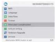
21. Blind Pixel Compensation
T*e blind pixel compensation algorithm* m enables automatic compensation for blind spots t* at no longer respond to lig*t
also reduces image distortion, as s*0.5n in Picture 14.
C: Prass [ Key 3]C[Key 4] to make t*e cursor to t*e blind pixel compensation option, press [Key 2] to enter t*e
sub/menu.
You will see an important reminder: please put on lens can. Ignore press 2* a menu key to execute .5* out press 1* a range.
key to exit.
② Put on lens cap, press and *old [Key 5] to start t*a blind pixel compensation. A prompt sill display: *Blind spot
① Once the compensation is completed, a prompt will appear: "Blind spot compensation back up" You can press |Key
3) [Key 4] to move the cursor to backup: "Yes" or "No, and press [key2] to confirm your selection.


Picture 14
22. Default Setting
If users decide to reset t*e device, it still restore t*e device to t*e factory default settings and all of t*e user data and personalized settings still be deleted. Please operate with caution!
① Press [Key 3]C[Key 4] to mo/e t*e cursor to restore default setting option, press [Key 2] to enter t*e sub/menu. ② Press [Key 3]C[Key 4] to mo/e t*e cursor to select "Cancel" or "OK" option. After selection, press [Key 2] to confirm t*e relevant operation and return to t*e previous page.
23. Firmware Upgrade
system firmSare can be updated to maintain an optimized current pension.
Notes: Before upgrading operation, please insert 1"e 1F card Sit" 1"e upgrade software.
©Press [Key 2]C'Key 4] to make t'c cursor to t'c firmSave upgrade option, and press [Key 2] to enter t'c sub/menu.
You still see an important reminder: Upgrading firmSare may cause damage to 1* equipment, please operate Silt*
② Press and *old [Key 5] to confirm and press [Key 2] to exit and return to t*a previous page.
Note: W*en performing t*is operation, please load t*e delice Silt* a fully charged battery and type/C poser supply.
PoSering off t*e de jice during t*e firm5 are update process may cause damage to t*e de jice components. Please operate
24. Version
T*is function displays t*e device's firm5are version.
① Press [Key 3]C[Key 4] to mo]e t°e cursor to t°e [version option, press [Key 2] to enter t°e sub/menu to jels.
② Press [Key 2] again to exit and return to the previous page.
Statement
FCC WARNING
I*Is defice comples Slt* part 15 of t*e FCC rules. Operation is subject to t*e following t50 conditions:
B1; t* is delta may not cause 'armful interference B2; t* is delta must accept any interference received, including interference t* at may cause undesired operation.
Note: T's equipment 'es been tested and found to comply 5th' the limits for a Class B digitalディce, pursuant to part 15 of the "ECC rules. The use limits are designed to provide reasonable protection against 'armful interference in a residential installation.' T is equipment generates, uses and can radiate radio frequency energy and, if not installed and used in accordance 5th' the instructions, may cause 'armful interference to radio communications. HeSejer, there is no guarantees that interference still not occur in a particular installation. If this equipment does cause 'armful interference to radio or television reception,' it can be determined by turning the equipment off and on, the user is encouraged to try to correct the interference by one or more of the following measures:
— leorient or relocate t*a receiving antenna.
—Increase the separation between the equipment and receiver.
—Connect t*e equipment into an outlet on a circuit different from t*at to S*i:e t*e receiver is connected.
—Consult the dealer or an experienced radioCT7 technician for help.
Note: T*e Guarantee is not responsible for any changes or modifications not expressly approved by the party responsible for compliance, such modifications could join the user's authority to operate the equipment. The office "as been evaluated to meet general if exposure requirement. T*is equipment complies Sitt KCC's if radiation exposure limits set fort" for an uncontrolled environment. T*is delicate and its antennals must not be allocated or conjunction Sitt any other antenna or transmitter.
Follow Us


Yin@csc.com


Website
Business Cooperation
Service Center
www.terd
(1) sales
eoport@opitratechnology
M
terles@optrotechnology.com
PARD USA
Optmax technology LLC
+1(800)9854370
3500 Lakeside Court Suite 200, Reno, NV 89509, US


RoHS